Chapters 16 & 17 – CS118 bracket install & RT1 Roll Trim assembly

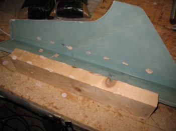
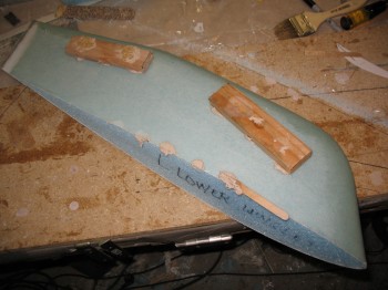
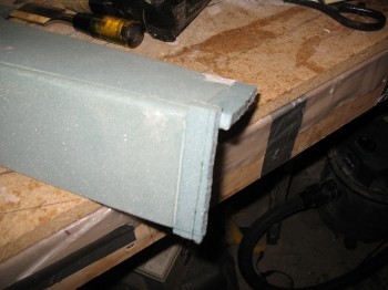
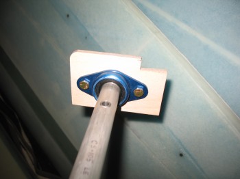
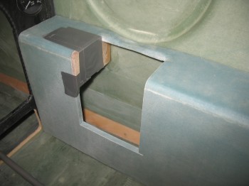
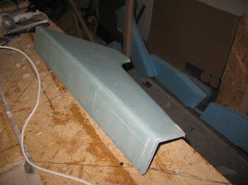
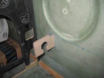
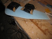
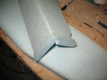
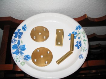
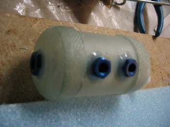
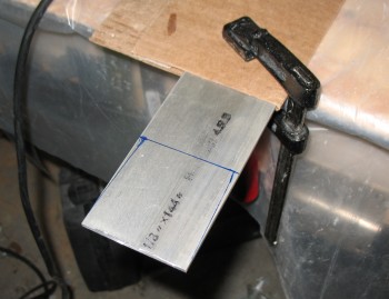
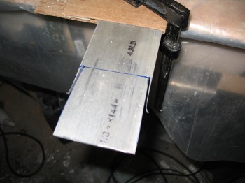
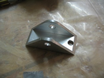
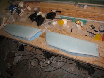
I started today by temporarily mounting the Right rear armrest console with tape.  In addition, I mocked up the rear control tube mounting bracket (CS118) to both the rear armrest & the right Rear fuselage sidewall.

Chap 16 - Control System Install

Also, the control tube was mounted into place at the forward control system mounting bracket (CS109).

Chap 16 - Control System Install

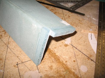
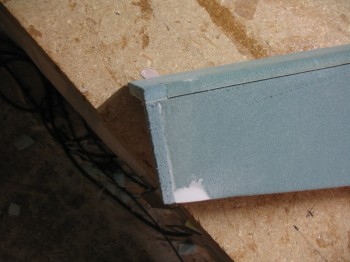
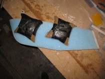
I had to recut the front of the Right rear armrest console in the tried & true mount-cut-remount-repeat process that is commonplace in building a Long-EZ.  I also had to slightly reshape the side of the rear armrest with the sanding block to get the fit locked in as close to perfect as possible, as well as getting the CS118 as close to 90° to the fuselage sidewall as possible.  Once it was all looking good & the fit was locked in, I 5-min glued the edge of CS118 bracket to the fuselage like I did previously in mounting the front CS109  bracket.

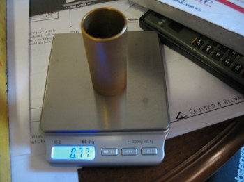
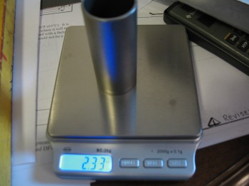
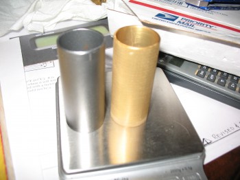
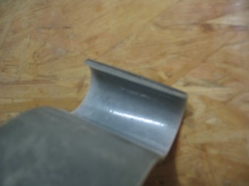
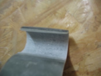
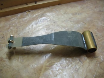
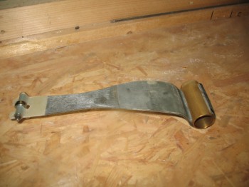
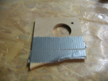
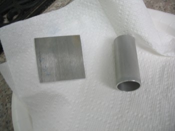
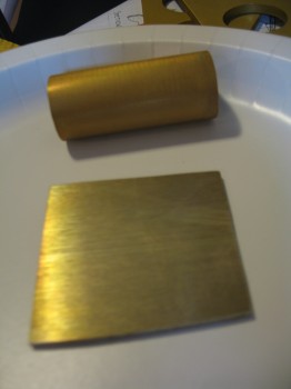
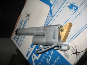
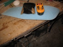
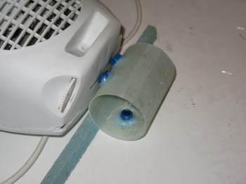
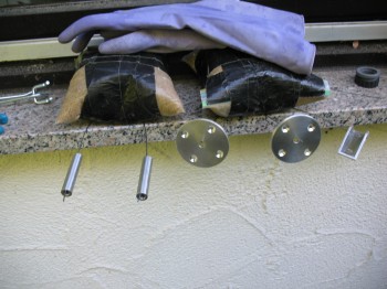
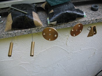
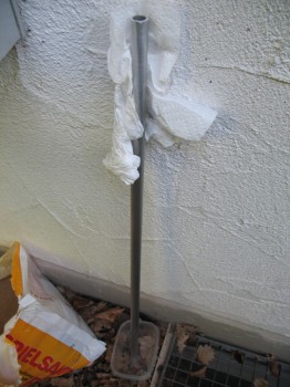
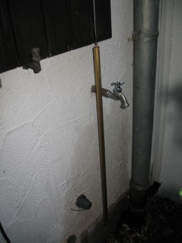
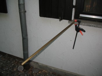
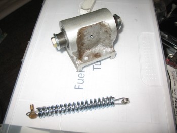
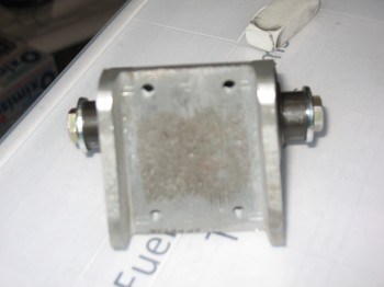
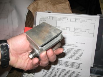
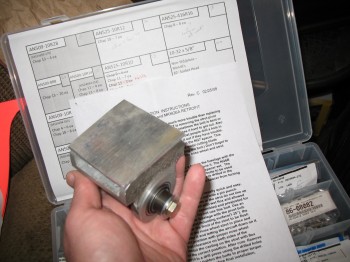
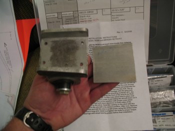
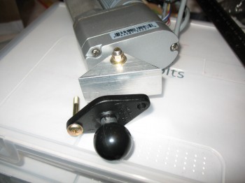
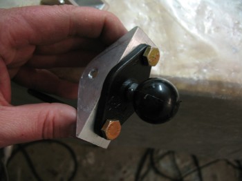
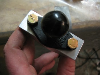
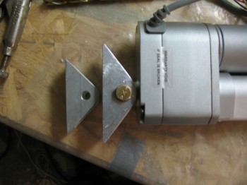
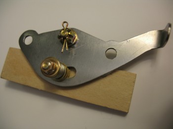
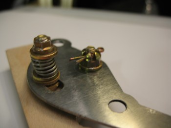
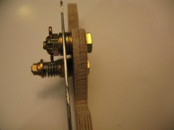
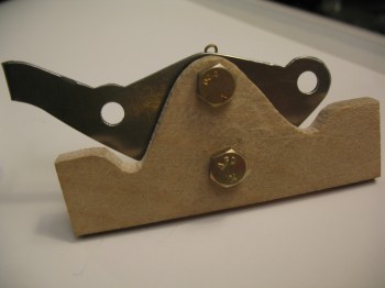
While the 5-min glue was doing its magic in bonding the CS118 mounting bracket to the fuselage sidewall, I took some time to assemble yet another new toy my buddy Marco had machined for me: the 4130 Steel RT1 Roll Trim Handle (he sent it with the Davenport mounting tube that I just covered in my previous posts).  Once again, he did an awesome job in making this out of a blank steel sheet.  You can see his post on the RT1 machining process here.  As for the Birch plywood mounting tab, I had cut that out last year while at the wood shop on base.

Chap 17 - RT1 Roll Trim Assembly

Chap 17 - RT1 Roll Trim Assembly

Chap 17 - RT1 Roll Trim AssemblyChap 17 - RT1 Roll Trim Assembly

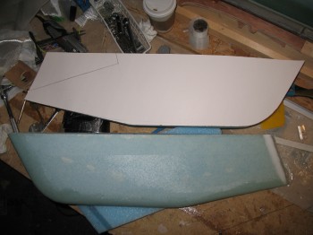
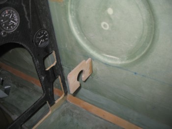
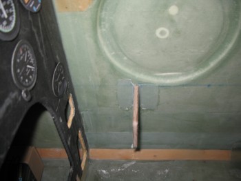
After playing around with my RT1 Roll Trim Handle it was time to get back to work on the CS118 control system mounting bracket.   Since the 5-min glue had cured, I pulled off the duct tape-mounted rear armrest.

Chap 16 - CS118 bracket install
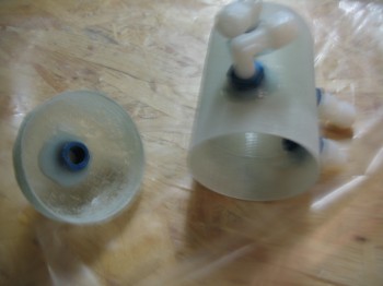
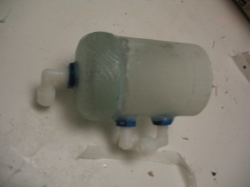
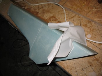
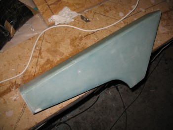
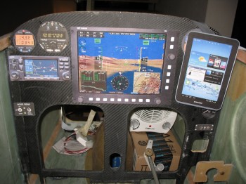
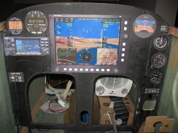
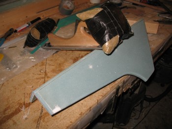
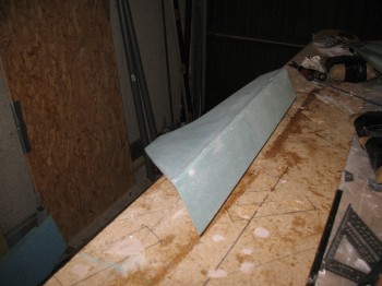
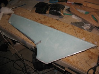
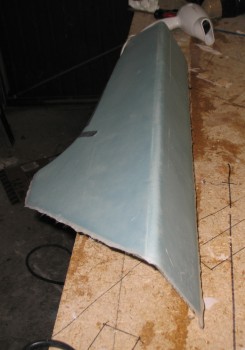
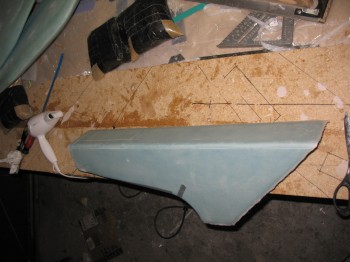
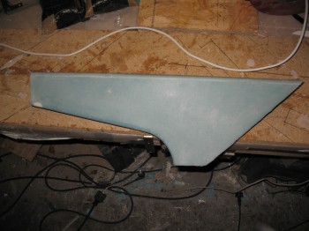
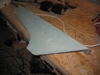
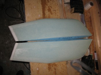
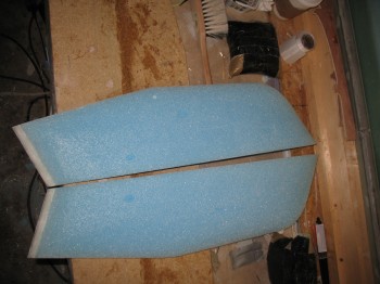
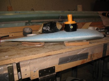
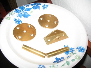
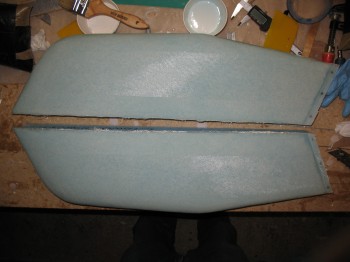
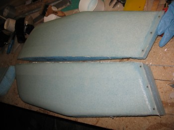
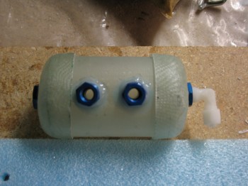
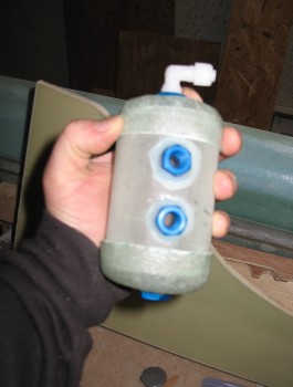
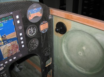
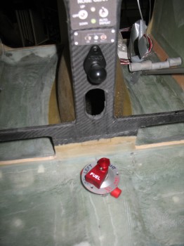
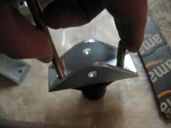
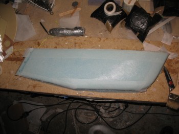
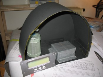
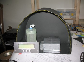
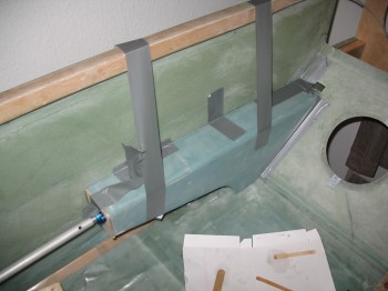
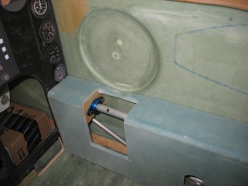
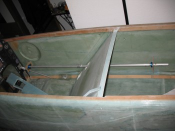
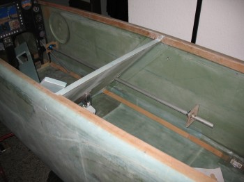
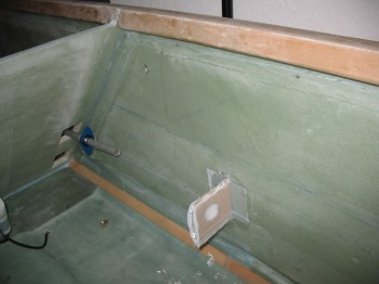
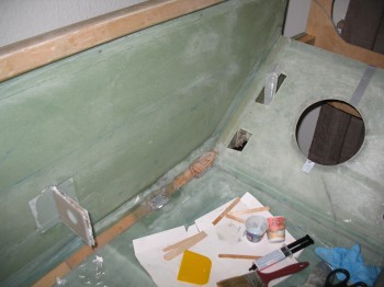
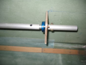
Here’s a couple shots of the initial barebones control system.

Chap 16 - Control System InstallChap 16 - Control System Install

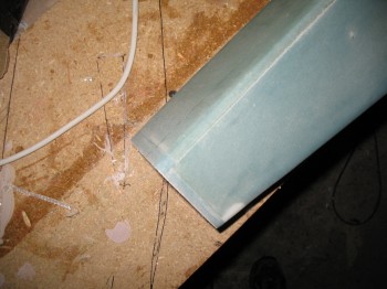
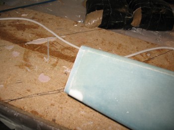
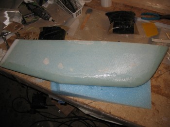
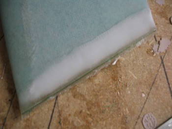
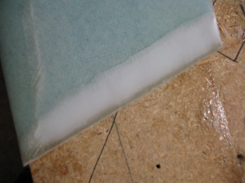
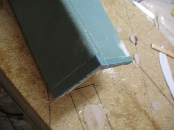
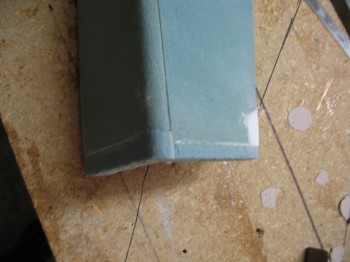
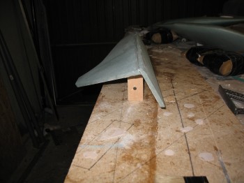
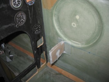
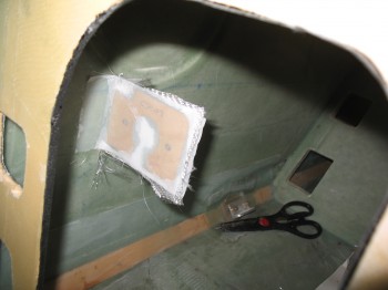
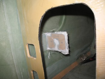
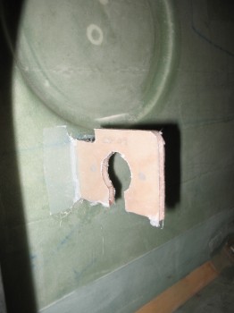
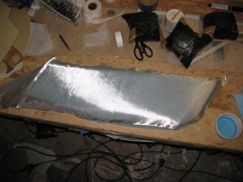
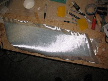
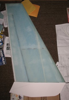
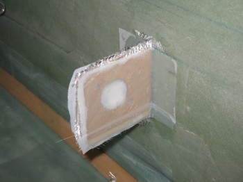
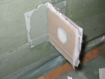
As I did with the foreward CS109 bracket I floxed in a small fillet in the corner between the CS118 bracket & the fuselage sidewall on both the front & back side of CS118 for a nice glass transition.  I then glassed a 1-ply BID layup on each side of the CS118 bracket overlapping about 1 inch onto the Right fuselage sidewall.  I then of course peel plied the BID layup on both the fore & aft side of CS118 & fuselage sidewall.

Chap 16 - CS118 bracket installChap 16 - CS118 bracket installChap 16 - CS118 bracket installChap 16 - CS118 bracket install

[I just wanted to add a quick note on my quality assurance during the layups here in these posts.  As I post these pictures I notice a number of them show peel ply with a number of dry splotches in the layup.  I just want to say that I’m sure like most builders, after the pics are snapped I go back over & over (some what obsessively often times) my layups to make sure they’re as close to perfect as possible, especially in getting that balance between having just enough epoxy to wet out the glass, but not having too much epoxy either.  I just wanted to clarify that a time gap often exists between the point a lot these pics are taken compared to the actual end of my layup efforts, and that while I’m trying to finish my Long-EZ in fairly quick fashion, quantity does not win out over quality.]


Chapters 16/17/21 – Floxity-flox-flox

Below is the 2.7″ long x 1″ diameter tube that I just received from my buddy Marco.  Again, he was nice enough to cut & cross hatch this piece of 6061 aluminum for me as a replacement for a slightly corroded 4130 tube piece that had been attached to my Davenport leaf spring.

To recap, this short tube slides over and is attached to the elevator torque tube, so when the pitch trim actuator arm extends or retracts it moves the narrow end of the leaf spring either fore or aft, thus rotating the elevator torque tube & in turn adjusting the elevators slightly up or down to trim out the airplane.

I used 6061 aluminum as a replacement to the original steel piece for 3 reasons: 1) It was available in the correct Inside & Outside diameters vs 2024 aluminum.  2)  Weight. Obviously 6061 is much lighter than 4130 steel (see 2.33 vs 0.77 oz weight comparison below).  3)  Although this piece won’t be mounted in the elements, 6061 has better inherent anti-corrosive properties than 2024 and especially compared to 4130 steel.

Chap 17 - 6061 elevator attach tubeChap 17 - 4130 elevator attach tube

Chap 17 - 4130 & 6061 elevator attach tubes

Next I prepared the surface of the Davenport leaf spring where I had previously removed the steel attach tube in order to flox in the 6061 aluminum attach tube.  I used some sand paper and my ever trusty PermaGrit tools.

Chap 17 - Davenport pitch trim leaf springChap 17 - Davenport pitch trim leaf spring

I then floxed in my newly machined (thanks Marco!) and Alodined 6061 attach tube into the glass attach “hook” of the Davenport leaf spring.

Chap 17 - Trim spring w/ attach tube floxedChap 17 - Trim spring w/ attach tube floxed

I have no idea where my brain was when I initially worked out my dimensions for my Right rear armrest console configuration, but somehow I even managed to come up short on my rear control system mounting bracket (CS118).  The CS118 attaches to the front of the rear Right armrest & has a hole in it (like the front attach point) that allows the aileron control tube bearing assembly to be mounted to the bracket with the actual control tube traversing through the mounting bracket, behind/under the Right rear armrest as it travels on its way back to the firewall.  Thus, due to my apparent inability to measure anything correctly that day I had to add to its height.  I had some Birch plywood that would have worked, but since it was just about 1/4″ that needed adding I used H250 foam to make it lighter.

When I mixed up the flox for the install of the Davenport leaf spring attach tube shown above, I made up enough to attach this H250 foam extension to CS118 (below) and also to flox one of the Fuel Vent Manifold end caps into place.

Chap 16 - Extending CS118 control sys bracketAnd here’s the Fuel Vent Manifold end cap being floxed permanently to the cylindrical manifold body (I’ll blame the blurry pics on my camera being tempermental).

Chap 21 - Floxing on fuel vent end capChap 21 - Fuel vent end cap floxed


Chapter 13 & 17 – More Alodining

Along with the nose gear strut attach plate (NG5), I Alodined a 2.7″ long x 1″ diameter tube that I just received from my buddy Marco.  He was nice enough to cut & cross hatch this piece of 6061 aluminum for me as a replacement for a slightly corroded 4130 tube piece that had been attached to my Davenport leaf spring.  This short tube slides over and is attached to the elevator torque cross tube, so when the pitch trim actuator arm extends or retracts it moves the narrow end of the leaf spring either fore or aft, thus rotating the elevator torque cross tube, in turn adjusting the elevators slightly up or down to trim out the airplane.

Chap 13 - NG5 & Chap 17 - Elevator attach tubeChap 13 - NG5 & Chap 17 - Elevator attach tube

I also did some research on autopilots, specifically checking out the Trio autopilot models. I also built a couple of cardboard & duct tape mockups for the Garmin GNS430W GPS & Trio Gold Standard servo.  I played around with the position of those components for a while in the avionics bay behind the instrument panel.


Chapter 16 – Right Rear Armrest

I really didn’t do too much today since I was busy prepping for my upcoming move.  I started out finishing up on the Right rear armrest console.  I razor trimmed & sanded the edges, and then I pulled the peel ply.

Chap 16 - Right rear armrest

Chap 16 - Right rear armrest

After I pulled the peel ply off I inspected the layup.  It looked pretty good & I was happy with my repair actions.

Chap 16 - Right rear armrestChap 16 - Right rear armrest

Since it all looked good, I went ahead and popped the armrest off its 2×4 wood perch.

Chap 16 - Right rear armrest

Clearly I have a few bondo blobs to clean up.

After cleaning up a little bit in the garage, I then went inside the house & spent an hour or so mocking up my instrument panel & figuring out some of my avionics, etc.

Chap 22 - Instrument panel mockupChap 22 - Instrument panel mockup


Chapter 16 – Control System & Armrest

I actually started today by popping the lower winglets off of the wood blocks that they were bondo’d to.  Then I chiseled a bunch of cured bondo off the winglet surfaces.

Chap 20 - Lower wingletChap 20 - Lower wingletChap 20 - Lower winglet

I then marked, cut & sanded the TE of both lower winglets.

Chap 20 - Lower wingletChap 20 - Lower wingletI then measured, marked & cut the foam I had micro’d to the front of the Right rear armrest console.

Chap 16 - Right rear armrest consoleChap 16 - Right rear armrest consoleChap 16 - Right rear armrest console

Once I had cut the Rear right armrest to the correct length I shaped the corner by rounding it over to match the existing corner radius.  I also radiused the bottom edge of the armrest as well (including the white micro repair patch).

Chap 16 - Right rear armrest consoleChap 16 - Right rear armrest console

I mounted a 2×4 on the workbench with wood screws and then bondo’d the armrest to the 2×4 to give me a nice solid, elevated surface to glass.

Chap 16 - Right rear armrest consoleChap 16 - Right rear armrest consoleChap 16 - Right rear armrest console

I mixed up some epoxy with fast hardener & made up some thick micro to fill the gaps & dings.  I then covered the rest of the armrest foam with micro slurry.  Once I was good to go with my micro prep, I glassed the armrest with 1 ply of BID.  I of course peel plied it as well (as well as a little duct tape to hold the glass to the foam on the bottom edge radius).

Chap 16 - Right rear armrest consoleChap 16 - Right rear armrest consoleChap 16 - Right rear armrest console

With the Right rear armrest BID layup curing I went to work on installing the front control bracket (CS109) for the flight control grip stick assembly onto the interior Right side of the fuselage.  To start I had to mark & drill 2 each #12 holes into CS109 (Birch plywood).  I checked the fit of the 2 bolts that will attach the control bearing assembly to CS109.

Chap 16 - Mounting CS109 control bracket

I then taped the control rod/bearing/CS109 assembly in position onto the Right front armrest console.  Once I was sure that it was positioned correctly, I 5-min glued the edge of JUST the CS109 control bracket to the Right interior fuselage sidewall.

Chap 16 - Mounting CS109 control bracket

I waited a little while (admittedly more than 5 minutes!) & then removed the tape and the Right front console, leaving behind just the now attached CS109 control assembly bracket.

Chap 16 - mounting CS109 control bracket

I then floxed filleted the corner between the CS109 bracket & the fuselage sidewall on both the fore & aft side of CS109.  I glassed a 1-ply BID layup on each side of CS109 that overlapped about 1 inch onto the fuselage side wall, and then peel plied the layup on each side of CS109 as well.

Chap 16 - mounting CS109 control bracketChap 16 - Mounting CS109 control bracketChap 16 - Mounting CS109 control bracket

While the CS109 bracket layup cured I returned to the garage to check on my Right rear armrest layup.  It looked good & cured enough that I could remove the duct tape.  I did, however, leave the peel ply on (I learned that lesson of removing peel ply too soon on my NG30!).

[Also, remember I peel plied the entire surface because per plans it simply gets installed into the fuselage with 2 plies of BID overlapping about 1 inch onto the fuselage sidewall. However, since I’m not mounting these right now & don’t want them to get tore up in the move, I’m glassing only 1 ply now, and then later I’ll add a corner BID tape & another full ply of BID when I do a final glass of the armrests into place.]

Chap 16 - Right rear armrest consoleChap 16 - Right rear armrest consoleChap 16 - Right rear armrest console

I then went back to check on my CS109 bracket.  I checked the layup and it was nearly completely cured (I used fast hardener) so I razor trimmed the bracket & fuselage side wall.

Chap 16 - Mounting CS109 control bracketChap 16 - Mounting CS109 control bracketChap 16 - Mounting CS109 control bracket

Here’s a shot of my pitch trim actuator with it’s new & improved larger Alodined bracket attached.

Chap 17 - Pitch trim actuator


Chapter 20 – Just winglet-ing it!

I started off today by sanding the lower winglets’ leading, bottom & trailing edges.  I sanded the TE trough and filled it with dry micro.

Chap 20 - Lower winglet

I cut off the lower winglets’ fish tail & removed the peel ply & nails, and then sanded to shape.

Chap 20 - Lower wingletChap 20 - Lower wingletChap 20 - Lower winglet


I transferred the cut UNI from my cutting table in my downstairs workshop to the garage.

I sanded the LE, bottom edge & TE for a smooth transition when I glassed the second side of the winglets.

Chap 20 - Lower wingletsI scrounged around & found 4 scrap pieces of wood as spacers & mounted them to the workbench with bondo.

Chap 20 - Lower winglet buildI then bondo’d the 2 winglets down to the workbench, using the scrap wedges to prop up the narrower bottom edges of the winglets so I had good solid platform at the appropriate angle to glass each winglet.  It also gave me clearance to wrap the glass from Side B for a 2 inch overlap onto the LE & bottom edges of the Side A glass.

I then weighed the winglets down while they cured.

Chap 20 - Lower wingletI used dry micro to fill in the plugs that were extricated from the foam when it was 5-min glued down to secure when I had glassed Side A.

Chap 20 - Lower winglets

I used micropaste with a little flox mixed in for my usual LE foam prep/fill.  Then microslurried the “field” on the winglets & glassed the 2-ply UNI layups (again, sequentially & one at a time).  Since I didn’t want to waste glass, on the Left lower winglet I started by laying up 2-pieces of UNI butted up against each other for the first layer, then covered that with the second ply which covered the entire winglet.  I then left the winglets to cure.

Chap 20 - Lower wingletsChap 20 - Lower wingletChap 20 - Lower winglet

When I first started working on the winglets by filling in the TE troughs with micro, I used the leftover micro to add 2 small foam pieces to the front of the Right rear armrest console to extend it just a little bit to meet the plans’ dimensions.  For some reason I had cut it too short, so I needed to fix that before I glass the outside surface of the armrest.

Chap 16 - Right rear armrest console repairAlso, I used the remaining amount of epoxy from the winglet layups to mix up a batch of flox to install the the final 2 each AN912 bushings into my fuel vent manifold body.  After I floxed them in, I set the manifold body in front of the heater to cure (the heater it’s leaning against is obviously not the heater being used).

Chap 21 - Fuel Vent Manifold


Chapters 13/19/20/21 – Alodining parts

Today I started off by Alodining 2 each NG8 brackets & NG14 spacers from Chapter 13, the pitch trim actuator bracket I just made for Chapter 17, and 2 each aileron torque tubes from Chapter 19.  I used wire held down by my mini sandbags to hang the smaller parts on to dry.

Chap 13 - NG8s, NG14s & pitch trim bracketChap 13 - NG8s, NG14s & pitch trim bracketChap 13 - NG8s, NG14s & pitch trim bracketChap 13 - NG8s, NG14s & pitch trim bracket

For the aileron torque tubes I used 1 meter long PVC pipes capped on one end to Alodine the tubes, and then I simply hung one up to dry and clamped a dowel to the window ledge with the torque tube slid over it for the other one to dry.

Chap 19 - Elevator torque tubeChap 19 - Elevator torque tube AlodinedChap 19 - Elevator torque tube Alodined

While I let all my freshly Alodined parts dry, I grabbed my lower winglets and razor trimmed the glass.  I also pulled the peel ply off the winglets.

Chap 20 - Lower wingletsChap 20 - Lower winglets

I then grabbed my Chapter 21 – Fuel Tank Vent Manifold parts and mocked it up.  I still have 2 more side bushings yet to install.

Chap 21 - Fuel Tank Vent ManifoldChap 21 - Fuel Tank Vent ManifoldChap 21 - Fuel Tank Vent Manifold


Chapters 13/17/20/21 – Allota stuff!

Today I received the NG6B from Jack Wilhelmson.  The NG6B is a “special modified NG6A with threaded internal bearing spacers with two AN5-15A bolts. For use when the AN5-41A bolt cannot be removed without cutting or drilling holes in the fuselage.”  (The spring in the pic just below is the spring that goes between the rudder cable & the rudder/brake pedals–one on each side.  I had the springs on hand, so I made this up. There are some ways to configure the rudder/brake system so it doesn’t require this spring which I’ll research out more . . . but just in case!)

Chap 13 - NG6B & Rudder Cable SpringChap 13 - Wilhelmson NG6B castingNow that my NG6B is here I can cut my 1/8″ thick 2024 aluminum stock to make the NG5, which is simple the plate opposite the NG6B that sandwiches the Nose Gear Strut & gives the screws a strong surface to compress against, like a clamp around the strut vs using only the fiberglass of the gear strut.

Chap 13 - NG5 Aluminum PlateChap 13 - NG5 Aluminum Plate

And here’s how the pieces look together.  Of course when mounted there are 4 screw holes in the NG5 plate & the nose gear strut sandwiched in between the NG6B & NG5.

Chap 13 - NG6B & NG5 nose gear upper attachChap 13 - NG6B & NG5 nose gear upper attachChap 13 - NG6B & NG5 nose gear upper attach

Next, I grabbed the 2 RAM ball mounts that I had just received from Aircraft Spruce to mock them up.  My initial plan is to have one RAM ball mounted to the Right-side fuselage wall in the hardpoint I embedded just aft of the instrument panel–as I have mocked up in the pic below.

Chap 22 - Side fuselage RAM mount

The other RAM ball mount will be mounted on the center instrument panel post.  The bolts used to attach this RAM ball mount will also serve to attach the bracket on the pitch trim actuator for my Davenport pitch trim system (also shown in the picture below is my Andair fuel valve).

RAM/Pitch Trim Mount & Fuel Valve

Chap 17 - Pitch Trim Actuator MountThe screw used in the above picture is a AN3- (3/16″) vs an AN4- (1/4″) screw/bolt that will be used to attach the RAM mount & pitch trim actuator bracket.  As I attempted to drill the 1/4″ holes on the original pitch trim actuator bracket I quickly noted that I had an issue with the bracket being too short.

Chap 17 - Pitch Trim Actuator MountAlthough I got one hole drilled, and it looked like it could work, the hole wasn’t actually equidistant from the center meaning that the other hole would be even further from the center line, and actually into the angled edge.  In short, I had to make another bracket to make this design work.  So I cut another, slightly longer bracket out of 1″ x 1″ 2024 aluminum U-Channel.

Chap 17 - Pitch Trim Actuator MountI drilled the 1/4″ holes & test fitted the RAM ball mount.

Chap 17 - Pitch Trim Actuator MountChap 17 - Pitch Trim Actuator MountBelow is a comparison between the original bracket & the new one that I just made.

Chap 17 - Pitch Trim Actuator MountNow, with the new pitch trim bracket completed I moved on to my Chapter 21 – Fuel Tank Vent Manifold.  I drilled a hole in the top (again, about 21/64″ in diameter) of the second cap and then test fitted the AN912 bushing.

Chap 21 - Fuel tank vent manifold capChap 21 - Fuel tank vent manifold capChap 21 - Fuel tank vent manifold capI then marked the first 2 (out of 4) side positions & drilled those holes as well.

Chap 21 - Fuel tank vent manifold

I then test fitted the two AN912 bushings into the side of the manifold, placed the new end cap in place and prepped all of the bushings & glass for floxing.

Chap 21 - Fuel tank vent manifold

I floxed in 2 AN912 bushings into the side of the manifold & floxed one AN912 bushing into the cap.  I set them in front of the heater to cure.

Chap 21 - Fuel tank vent manifold

Finally, I moved onto my Chapter 20 – lower winglets build.  I finished shaping the Right lower winglet.

I then shaped foam bases (from the original foam that the winglets were cut from & encased in when they were shipped to me) to mount the winglets to during glassing so that they would maintain their shape.  I screwed the foam bases to the work bench with 3 wood screws.

Chap 20 - Lower winglet

I mounted the lower winglets to the foam bases using 5-min glue & weighed them down while curing.

Chap 20 - Lower winglet

With the winglets mounted to the bases, I prepped them for glassing.  I vacuumed the winglets & tacked in a 1″ peel ply strip along the TEs.

Chap 20 - Lower wingletChap 20 - Lower wingletChap 20 - Lower winglets

I the micro’d the foam, working on only one winglet at a time.

Chap 20 - Lower winglet

I glassed each winglet using 2-plies of UNI at ±30° bias.

Chap 20 - Lower winglet

Chap 20 - Lower winglet

I then peel plied the edges after laying up the glass plies.

Chap 20 - Lower wingletChap 20 - Lower winglets


Chapter 20 – Lower winglets

1-4 June 2013

First off, I finished my D-deck mock-up & then made some cardboard and duct tape mock ups of the Electroair Electronic Ignition controller.  I placed the Electroair controller into the D-deck mock-up along with the fuel tank vent manifold and just the face-plate cutout of the GRT EIS-4000 control unit to see if there would be enough space.  As you can tell, it looks like there will be plenty of room.

Chapter 18 - D-deck mockupChapter 18 - D-deck mockup

Now, over the last few days I had researched a lot of different lower winglet designs & tried a number of different cutouts until I found the one I finally liked.  There is no drastic difference from the original stock plans lower winglet compared to my new design, which is really just a stock look but with a lower profile.

Chap 20 - Lower wingletMy finalized version of the lower winglet is 1.8 inches shorter top to bottom (or narrower if you look at the profile) than the stock plans version.  Also, the angle starting from the aft/trailing edge and moving forward to intersect the flat looking bottom line is moved significantly forward than the plans version.  These are essentially the “Mini-me” lower winglets of the plans version.  I cut out the new design with white poster board.

With my new winglet design in hand, it was time to get to work.  I started with the Left lower winglet, placing the template on top of the winglet and tracing out the template with a Sharpie.  I then simply cut along the marked line as close to 90° to both sides of the winglet as I could get it.

Chap 20 - Lower wingletChap 20 - Lower wingletChap 20 - Lower winglet

Once I got the basic shape cut out, I then had to hand sand the new lower winglet to its final form.  I used the unmodified Right lower winglet as a general guide to figure out the shape & rounded contour of its edge all the away around the bottom outline of the winglet.

Chap 20 - Lower wingletChap 20 - Lower wingletChap 20 - Lower winglet

Once I was 95% complete with the Left lower winglet, I started on the Right winglet.

Chap 20 - Lower wingletsChap 20 - Lower winglets