Chapter 13 – Peel ply jungle

I started out today by adding micro into the routed beds I made for the phenolic rudder pedal bases.

Installing pedal base with micro

I then spread a fine coat of epoxy on the bottom side of the pedal base and mounted it in the floor pan.  I also added a micro fillet in the corners around the perimeter of the floor pan.

Pedal base micro'd in place

The last step I performed when I was laying up the floorpans was to add a 3.5″ wide and 2.5″ high 2-ply BID layup between the aft bottom of the F22 center post and the fuselage floor.

F22-to-fuselage floor 2-ply BID

Here’s a shot of the glassed and peel plied floor pan.

Floor pan glass & peel plied

To ensure that each embedded rudder pedal base was perfectly level, I taped up a couple pieces of scrap wood with packing tape and then weighed them down over the rudder pedal bases.

Pedal base weighted for level surfacePedal base weighted for level surface

Here’s a shot of the weighed down rudder pedal bases.

Pedal bases weighted for level surface

While the floor pan layups cured I started back to work on the nose gear electrical system to finalize the conversion of the connectors to AMP CPCs.  I finalized converting the switch side (vs motor side) main connector P1 while concurrently cleaning up the wiring by zip tying the wiring.  I also cut all the terminated wires to the same length.

Nose gear connectors upgraded

Here’s a shot of the P1 connector (motor) and P2 connector (AEX) connected together.

P1 & P2 connectors connected

After a good 3-4 hours of cure time under a heat lamp, I pulled the weight off the rudder pedal base, razor trimmed the overhanging side glass and pulled the peel ply.  I also spent a good amount of time cleaning up all the peel ply goobers as well.

Glassed left side floor pan

I set the heat lamp up on the other side and ended working another 3-4 hours on the nose gear electrical connectors before cleaning the right side.  I still have to clean up all the peel ply boogers, but I’m calling it a night.

Glassed right side floor pan

Tomorrow I’ll test out the nose gear actuator with the new connectors.  I’ll also start working to finish the nose side walls.  And if all goes well, I may even get the gear strut connected to the actuator motor inside the gear box.


Chapter 23 – Nose panning

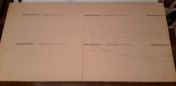
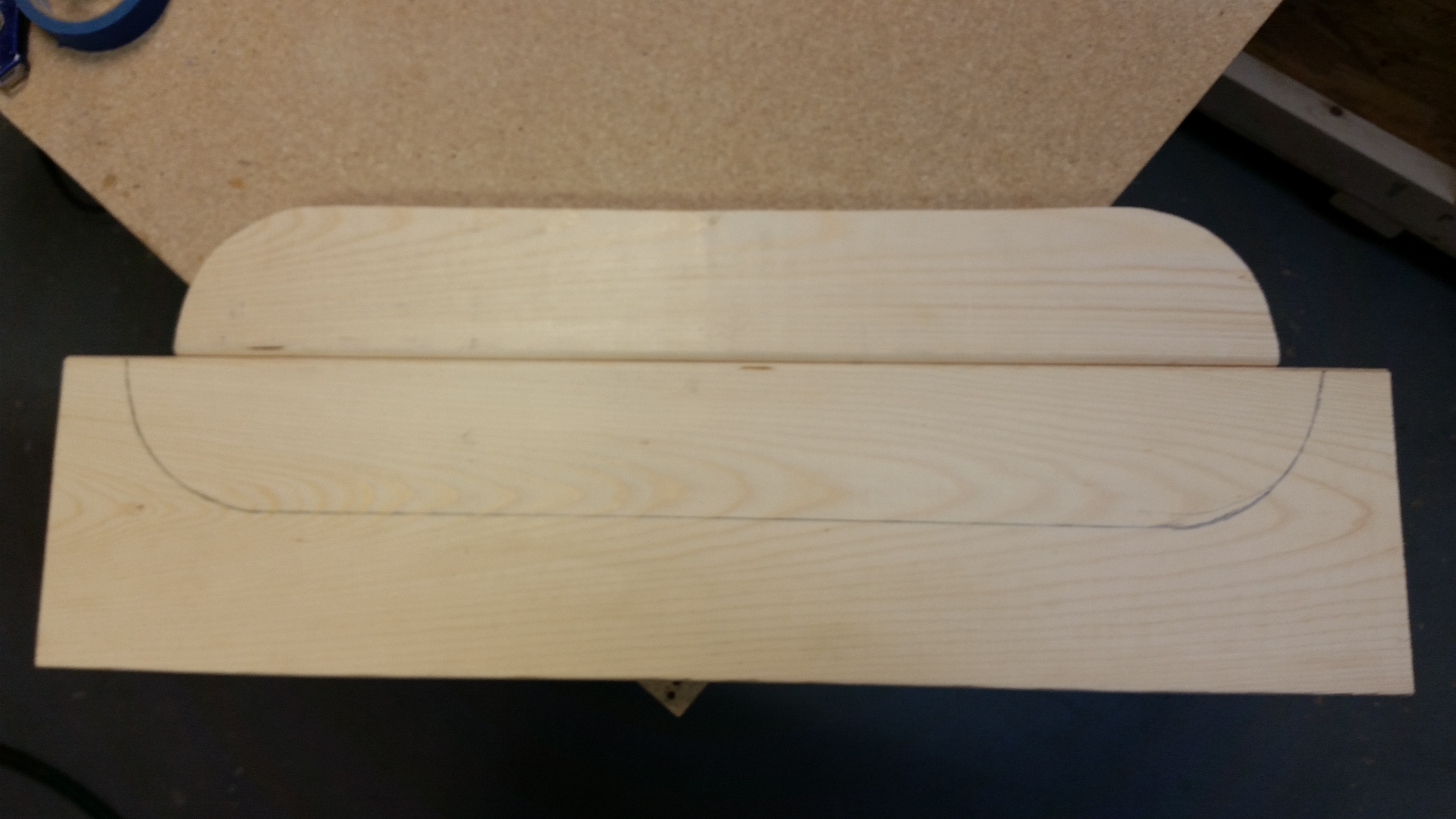
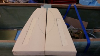
I started off today by marking up the area on the floor pans that gets dished out.  At this point, it was just for planning purposes since my main goal for today was to figure out the location to mount the rudder/brake pedals.  Once I figured out where the rudder pedals would go, I could then finish dishing out the floor pans and prep them for install.

Football! (Floor pan dish out…)

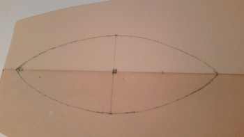
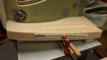
I also did the final mark up on the side panels that go between F22 & Napster.

Prepping side panels for final cuts

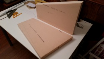
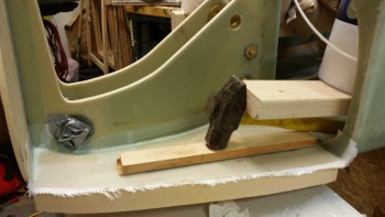
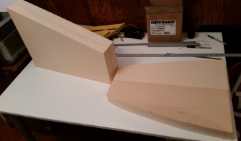
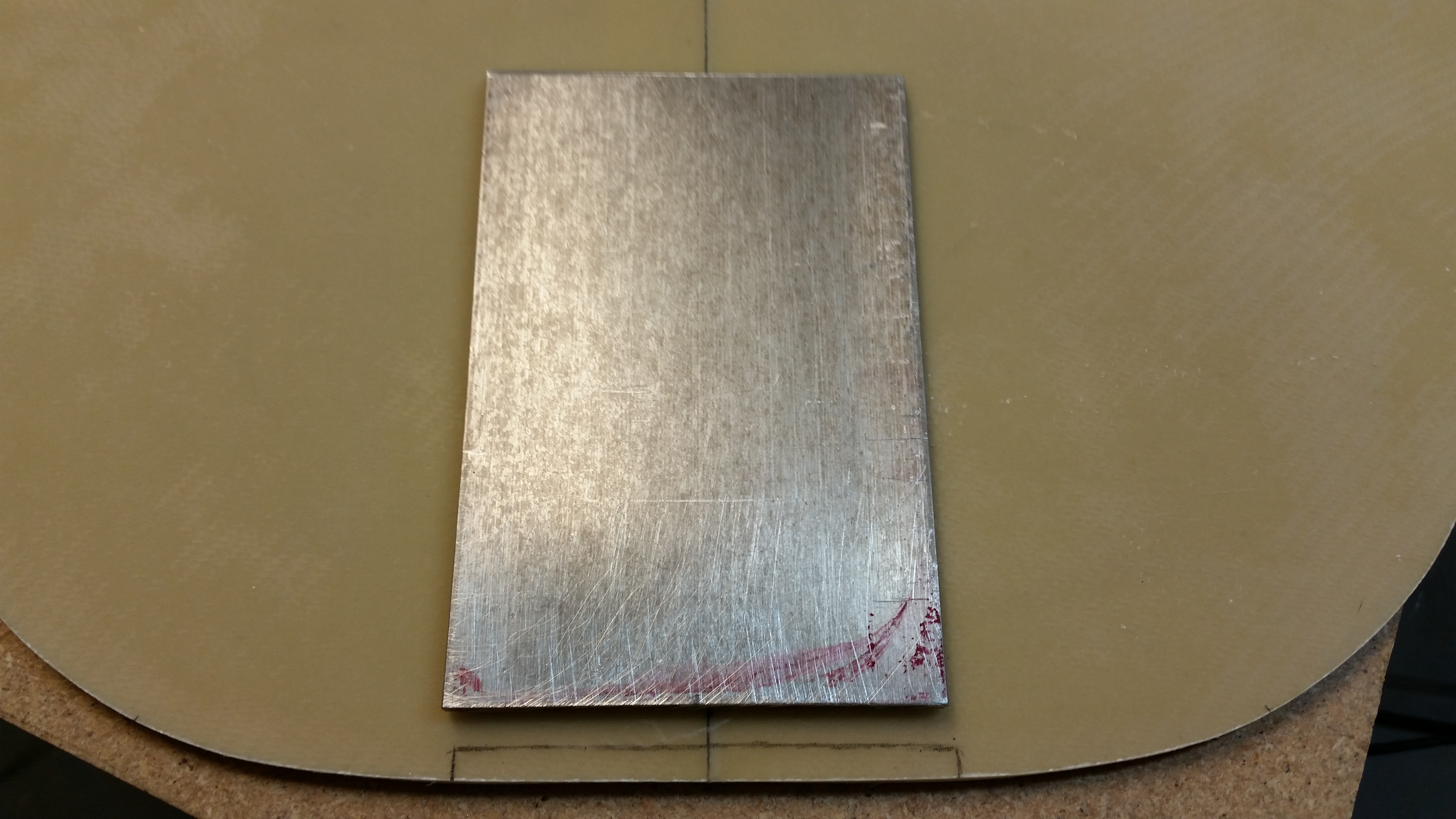
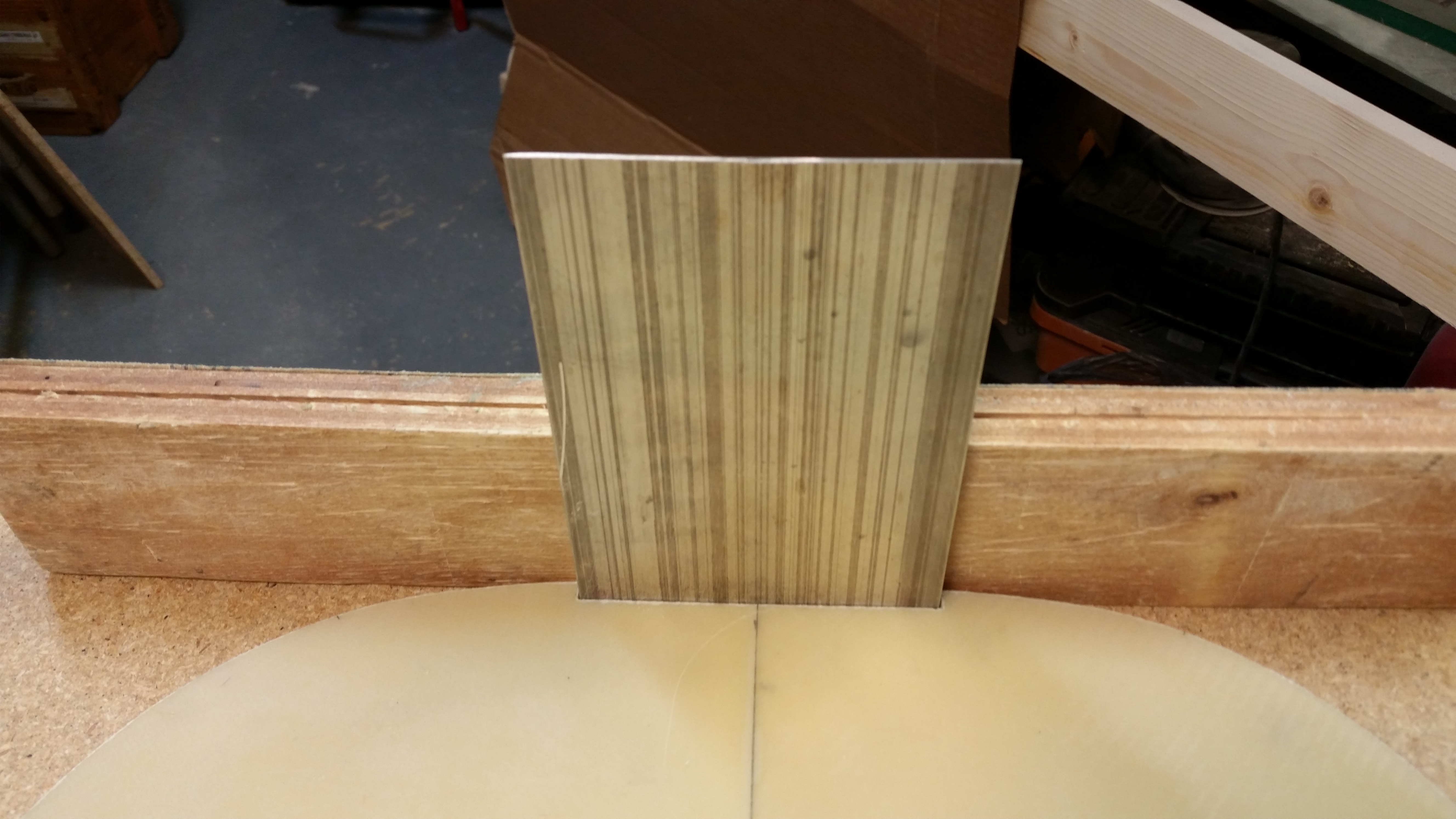
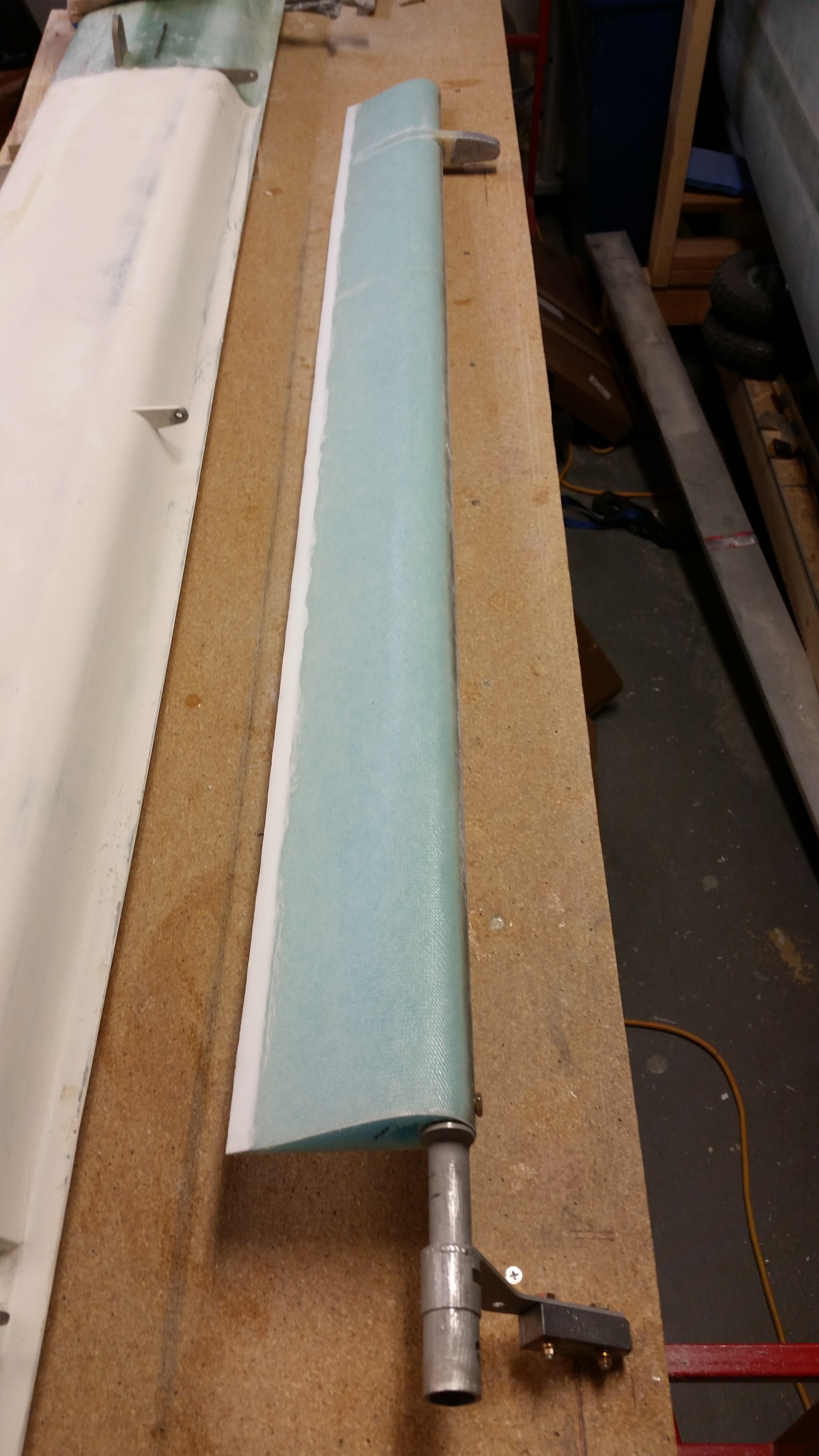
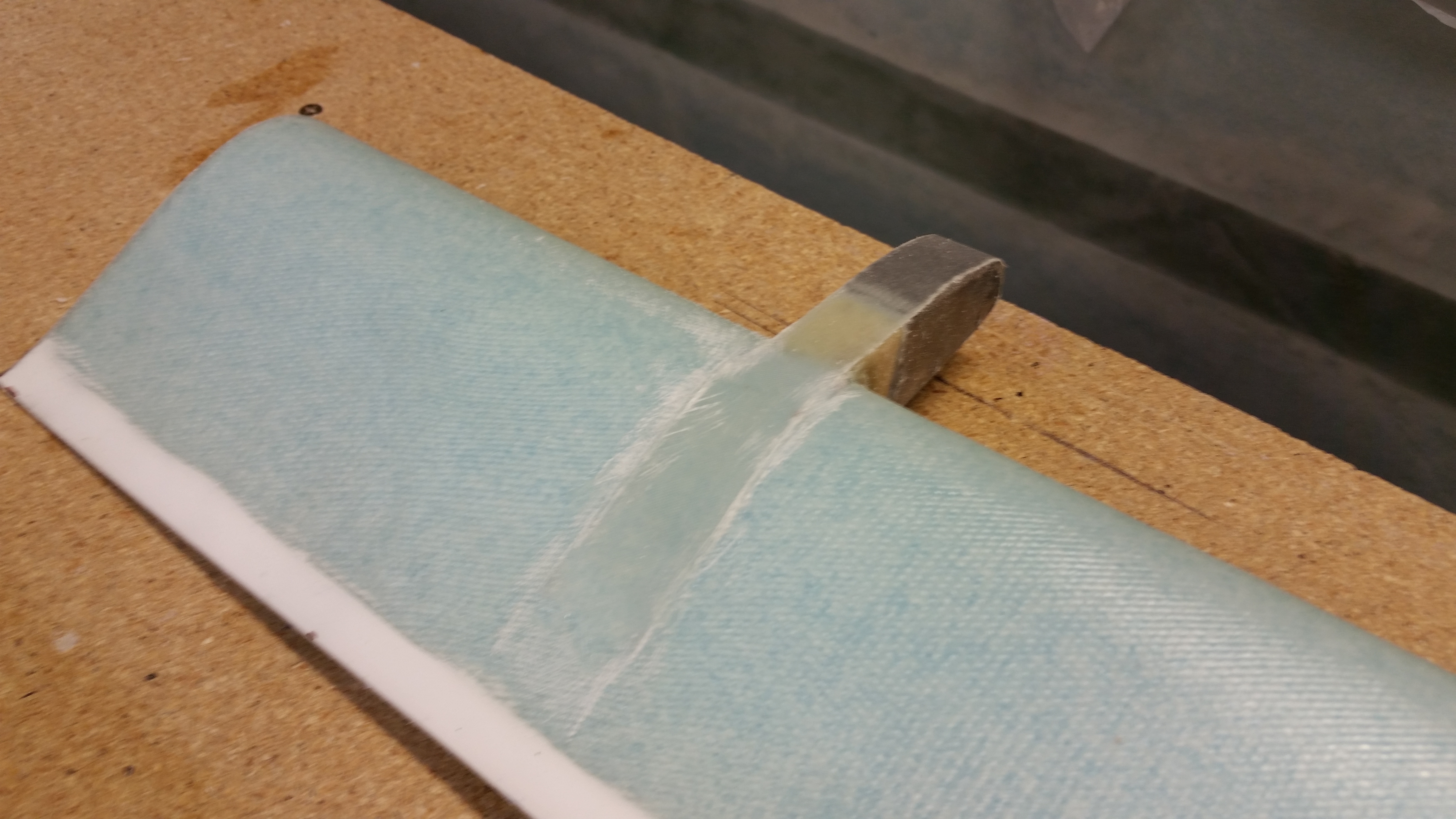
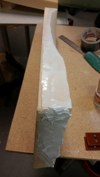
I then sanded the aft end of the floor pans to a 10° angle.

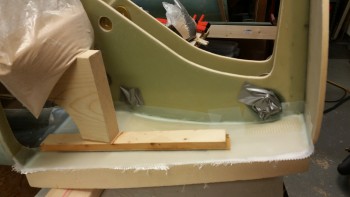
And cut & trimmed the left side panel (not pictured).  Although I widened my fuselage 1.4″ at the front seat back, my F22 is pretty much standard size.  So cutting the side panel to the listed dimensions should have gotten it really close to fit into the current F22-NG30-Napster configuration.  It was close on the aft side and ok on the bottom edge, but the front was pretty far off.  The angle called for was just too severe as compared to the actual F1-3 Napster aft lean.

Angling aft end of of floor pan

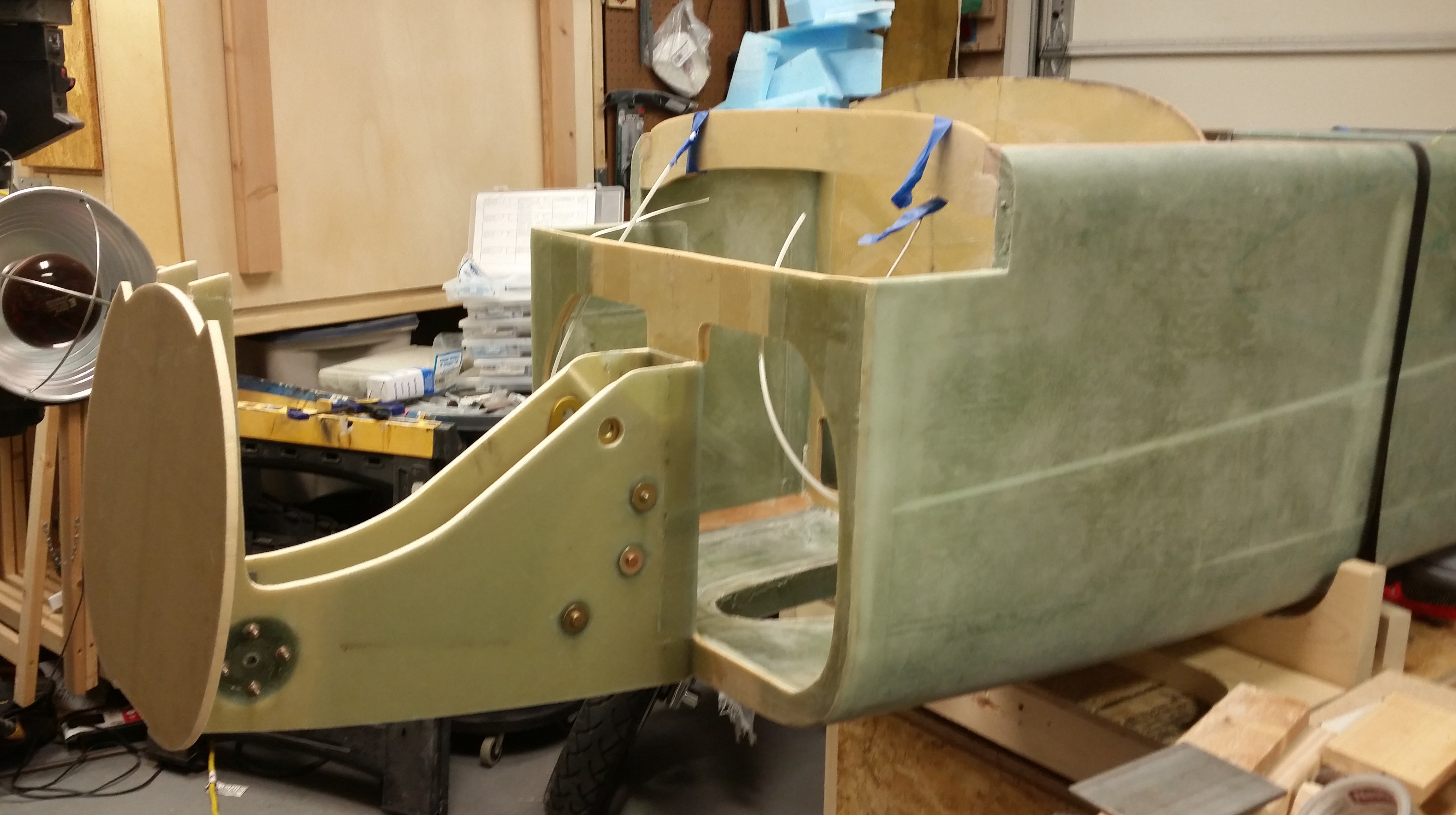
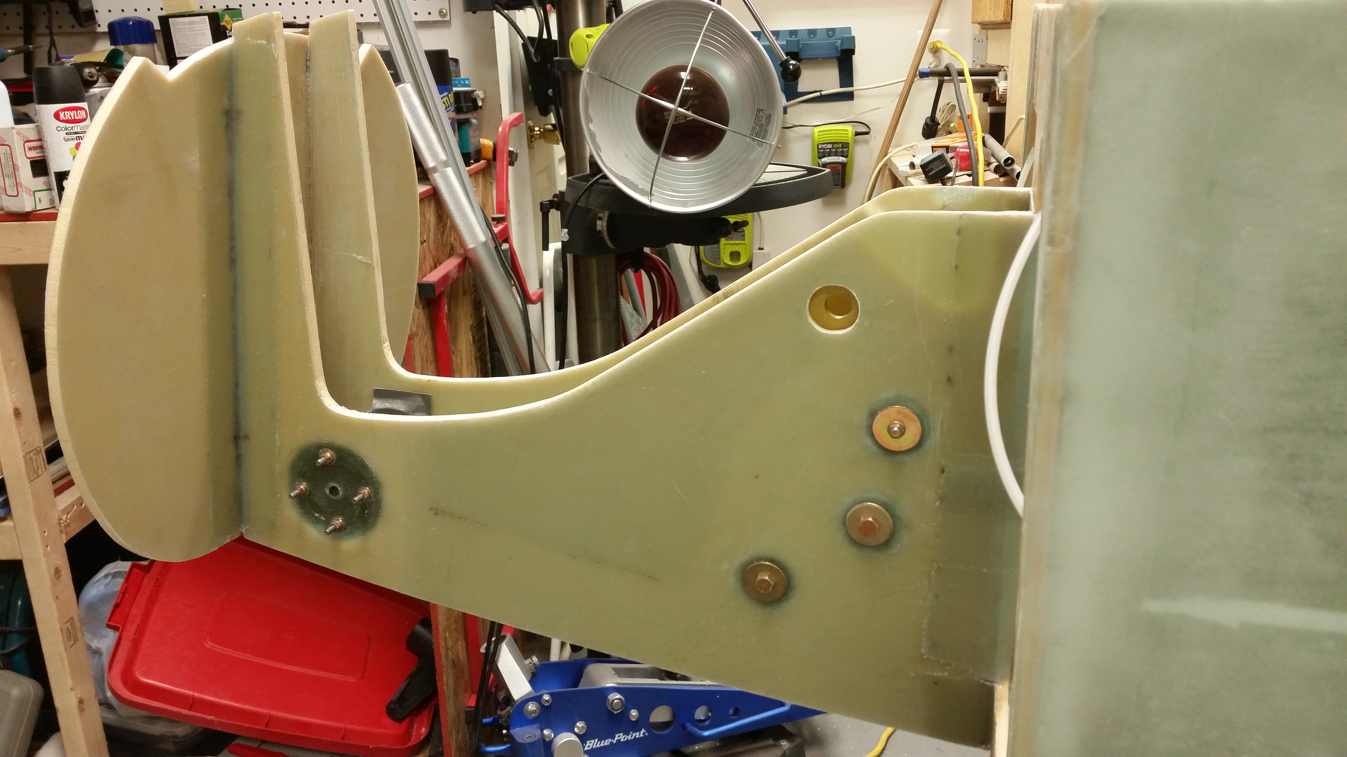
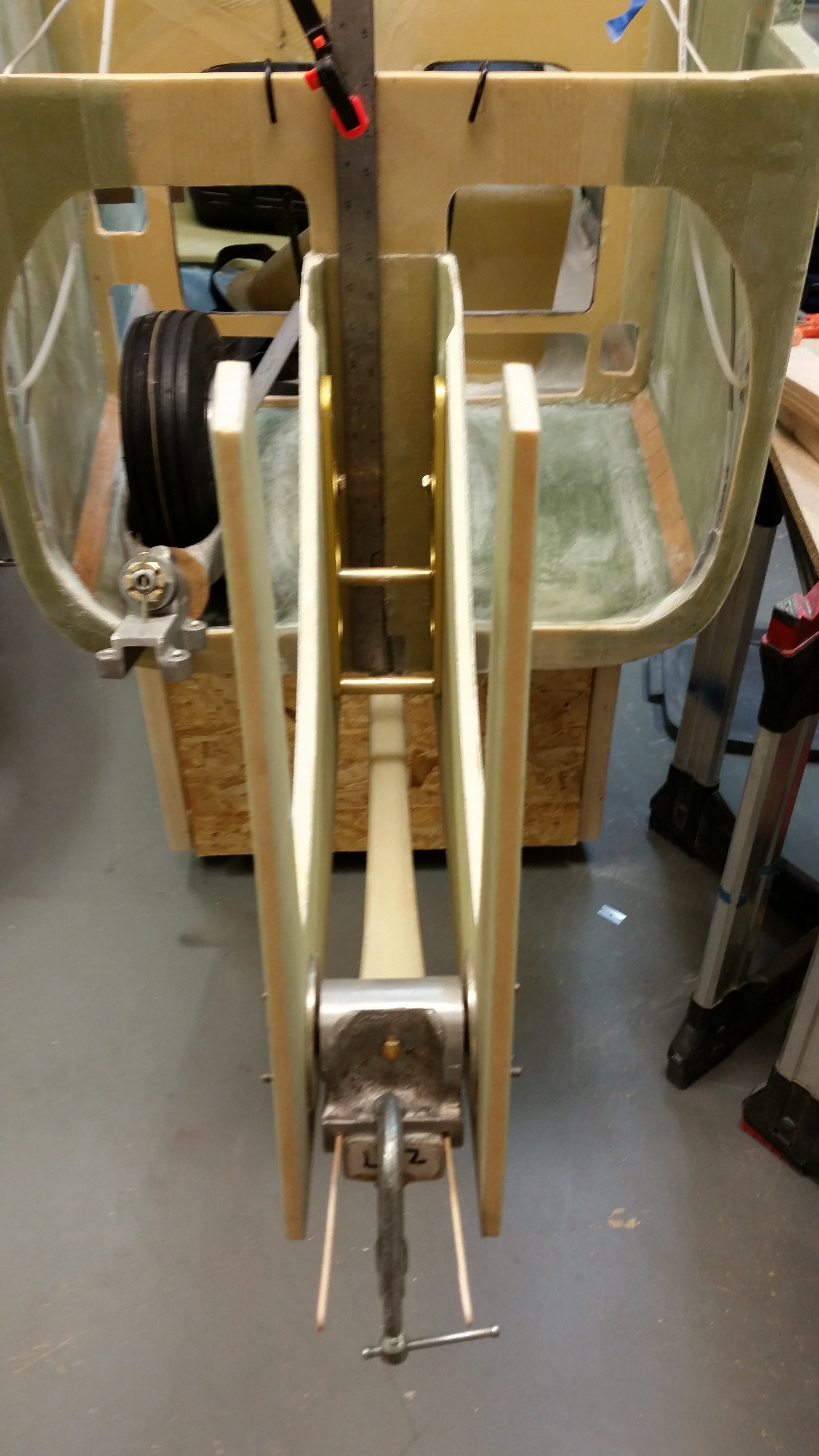
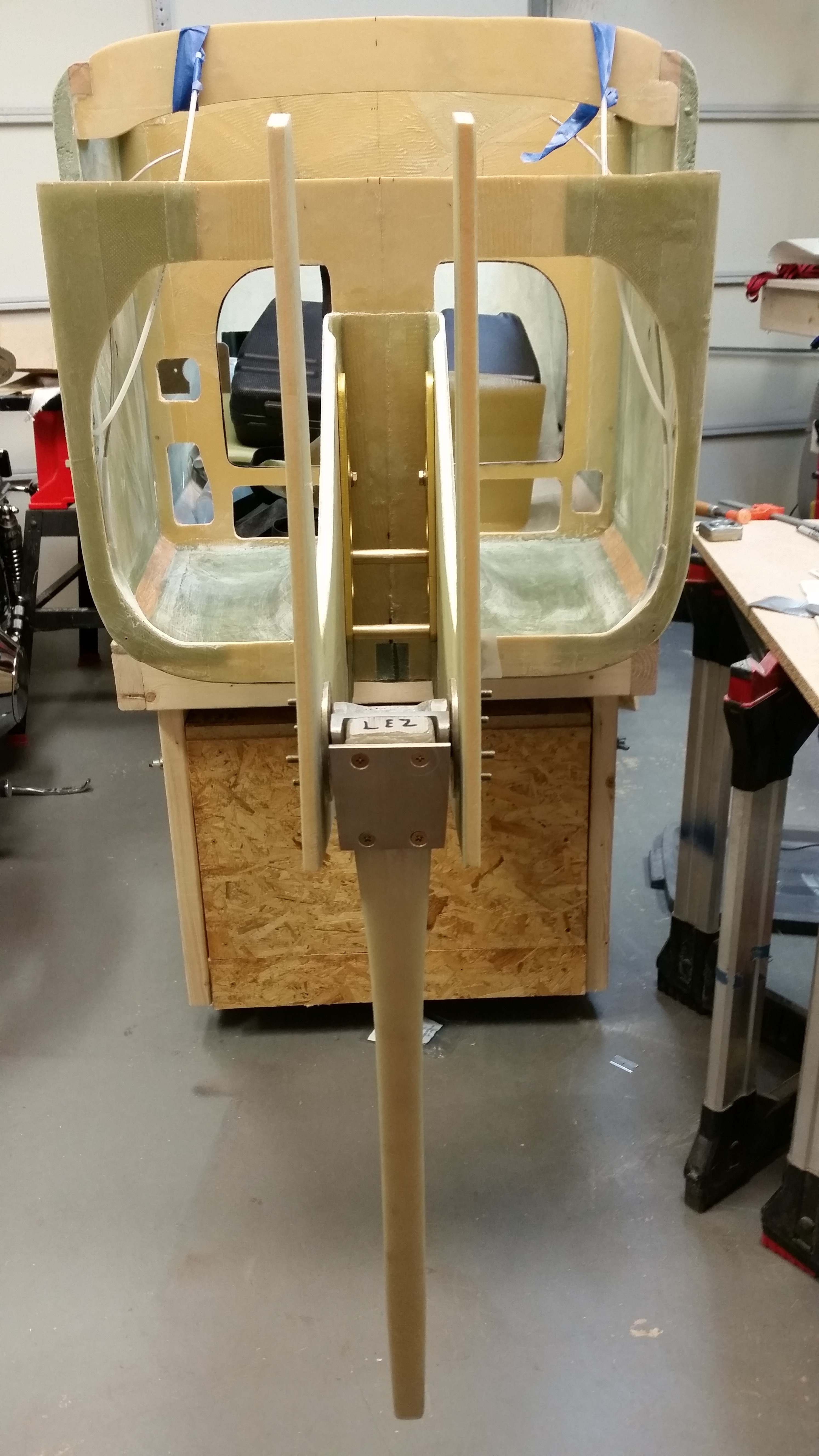
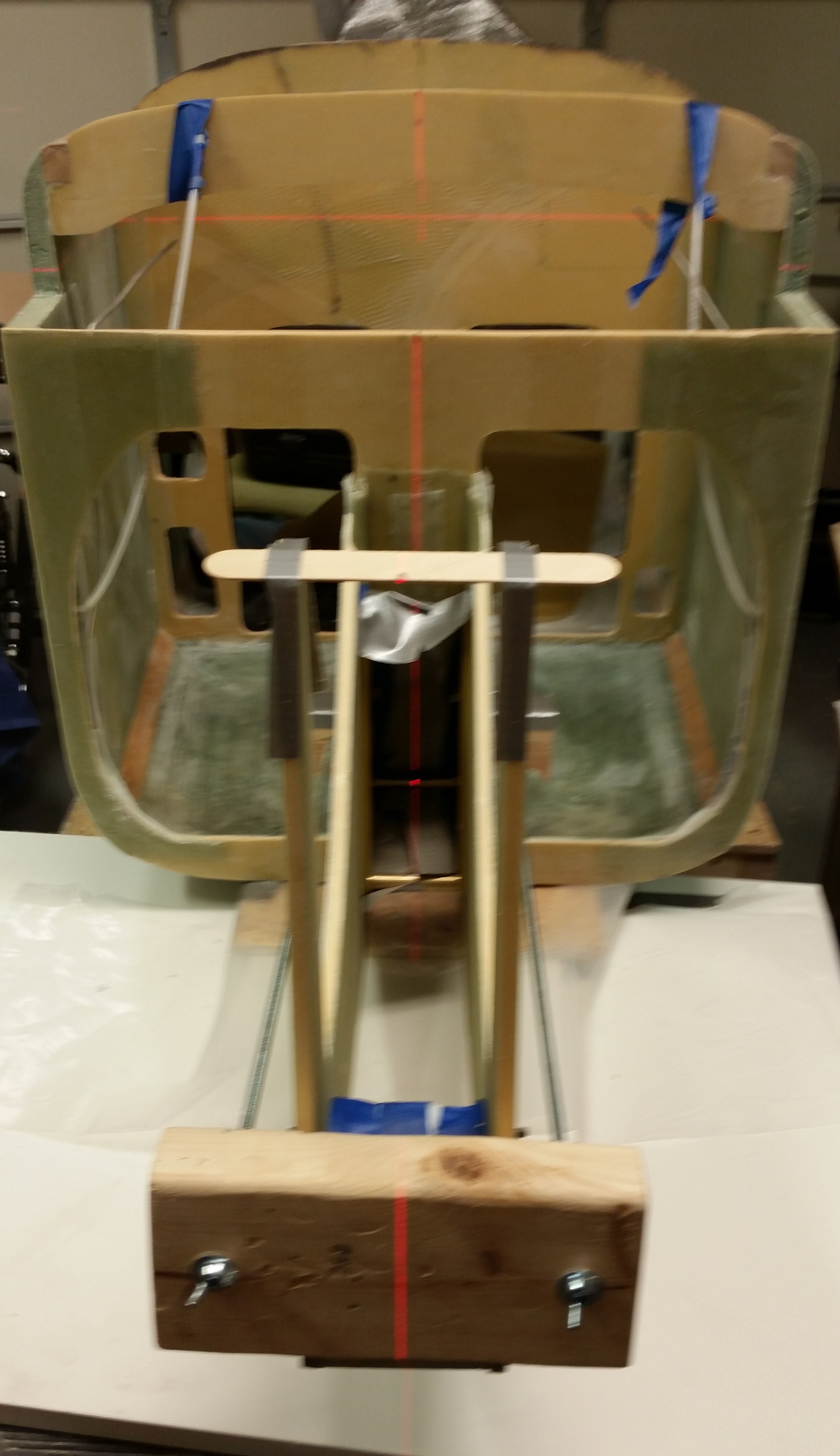
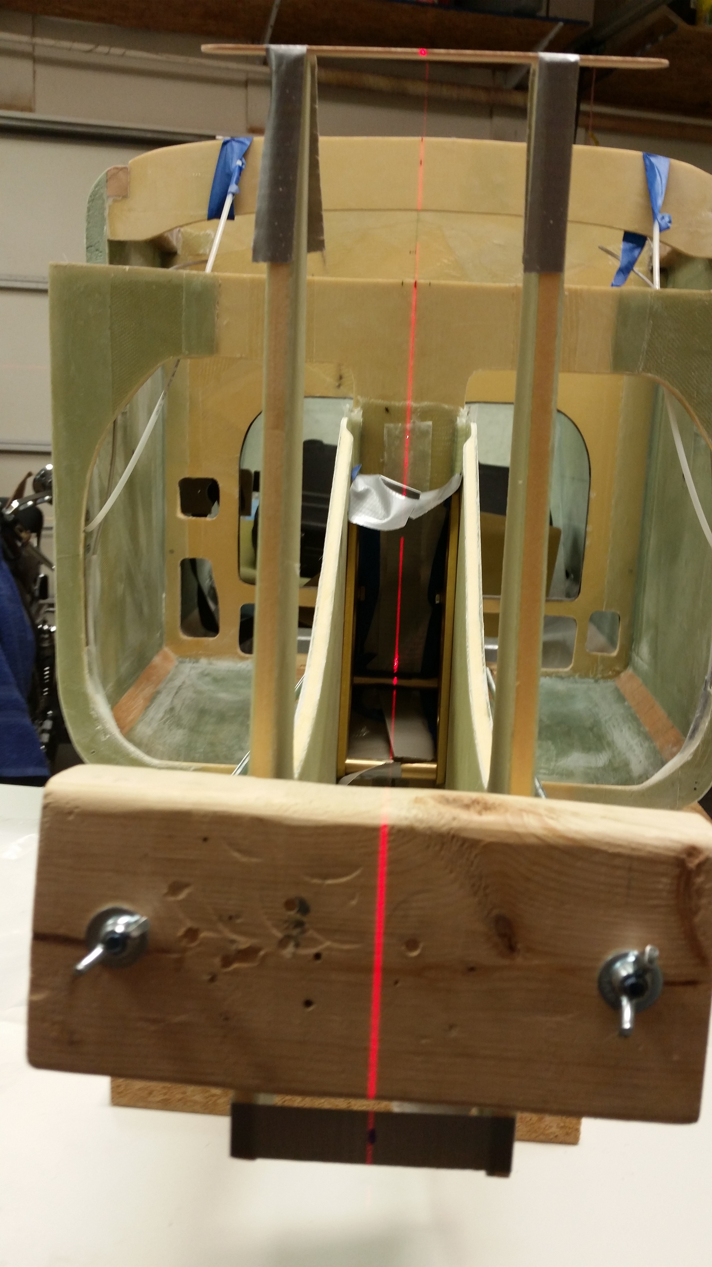
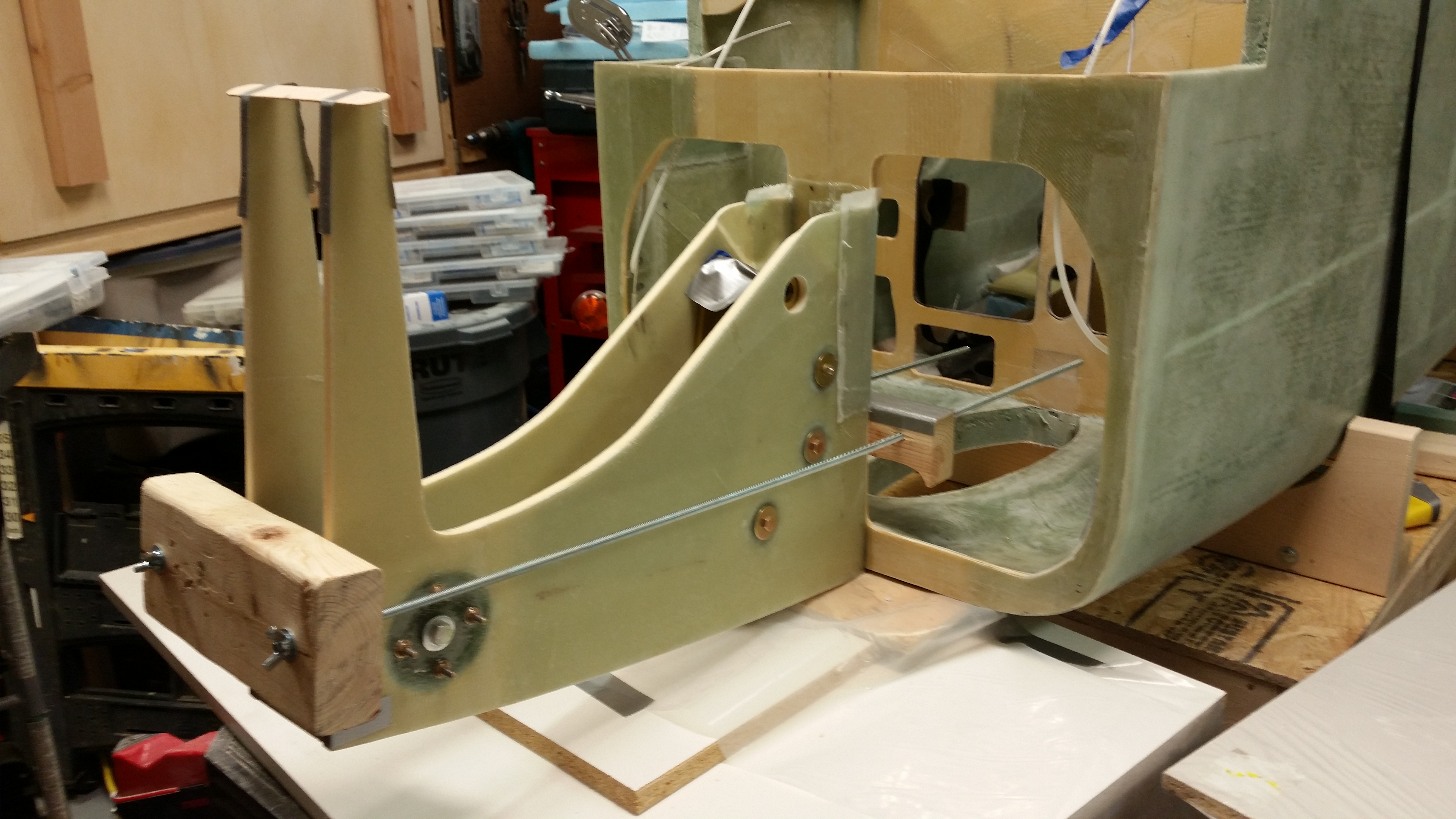
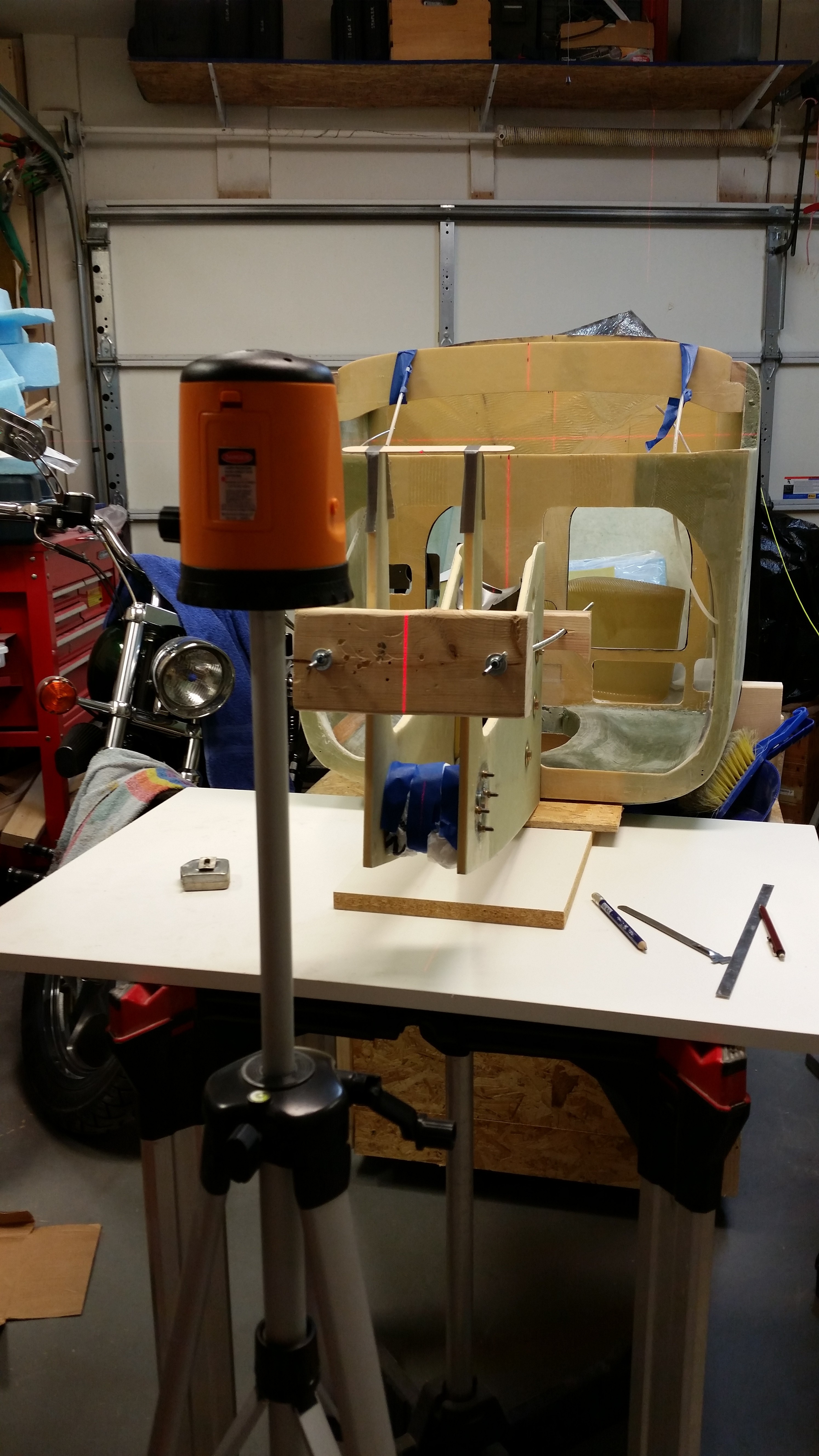
After messing around with the side wall for a while, and finally getting it into an acceptable shape to fit into place, I started mocking up the rudder pedals.  I spent a good hour doing research: comparing my buddies’ build sites, re-checking the plans, etc. as I tweaked the final location of the pedals.

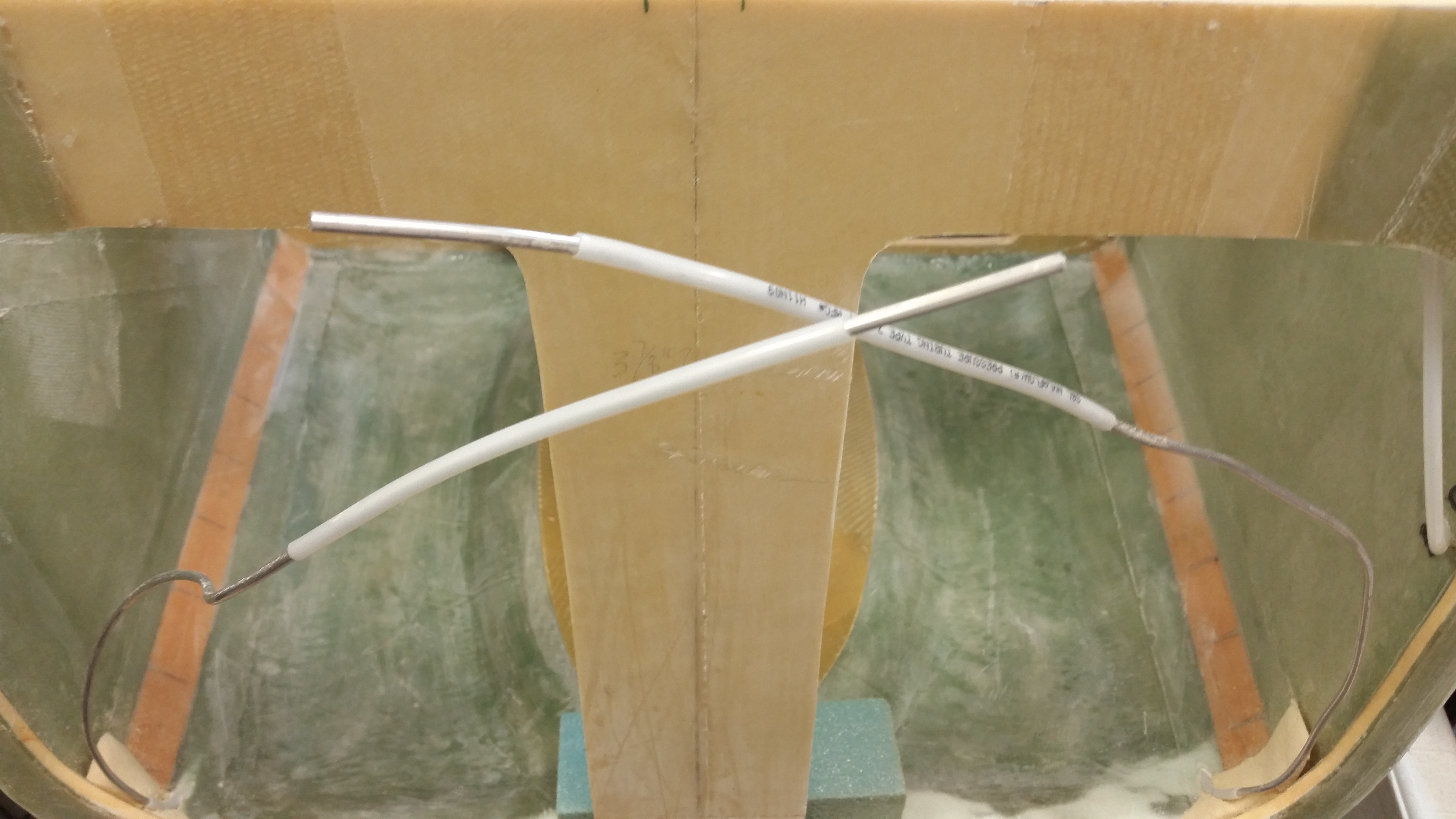
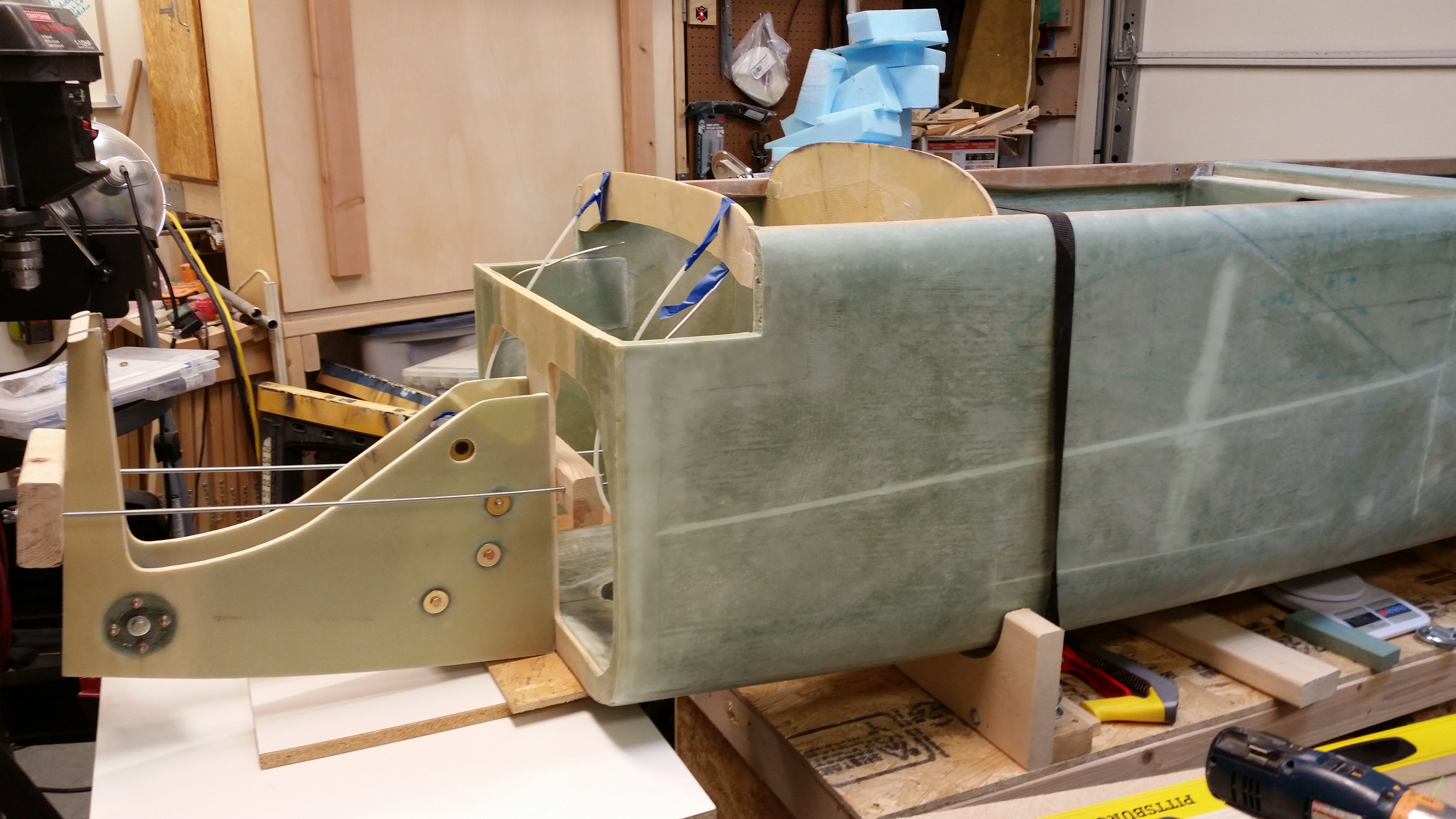
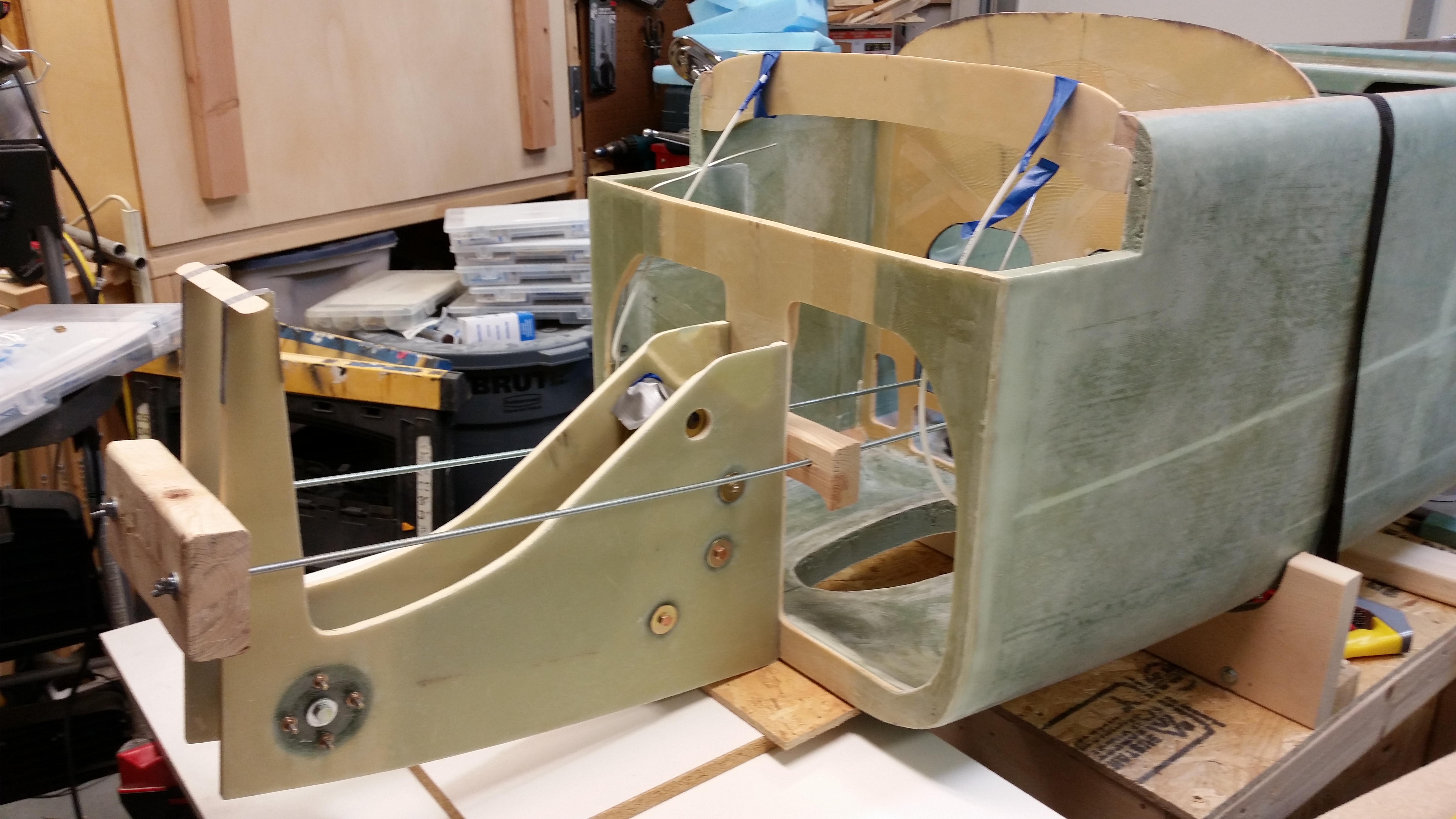
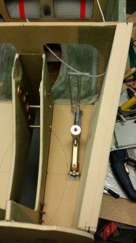
I also climbed into the fuselage and tried out my feet location to double check as well. Now, a couple things of note are that my rudder pedals are adjustable, but of course that’s only for fore & aft.  Also, the rudder pedal plans specifically state to keep the pedal 1-1/4″ away from the sidewall.  Part of the reason for me doing so much cross-checking in my research is that this 1-1/4″ clearance with the sidewall is a tall order in such a small space as the nose, especially since with the Davenport nose the sidewalls stay rather thick.  The bottom line is that as long as I have a good clearance with the sidewall, the 1-1/4″ clearance requirement is just not happening.

The main reason for ditching this lofty clearance requirement is that one of the really nice features of the Long-EZ is to remove your feet from the pedals while in cruise flight and resting them adjacent to the pedals, wherever they happen to be mounted (some folks mount them on the inboard side vs the outboard plans side).  Clearly, with the pedal mounted more towards the center of the foot/leg opening in F22, that diminishes the comfort of the pilot (me!) during flight.  So again, I’m chucking the 1-1/4″ clearance for a more reasonable one considering the tight quarters in the nose.

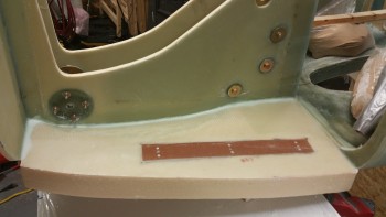
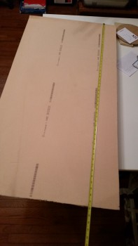
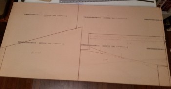
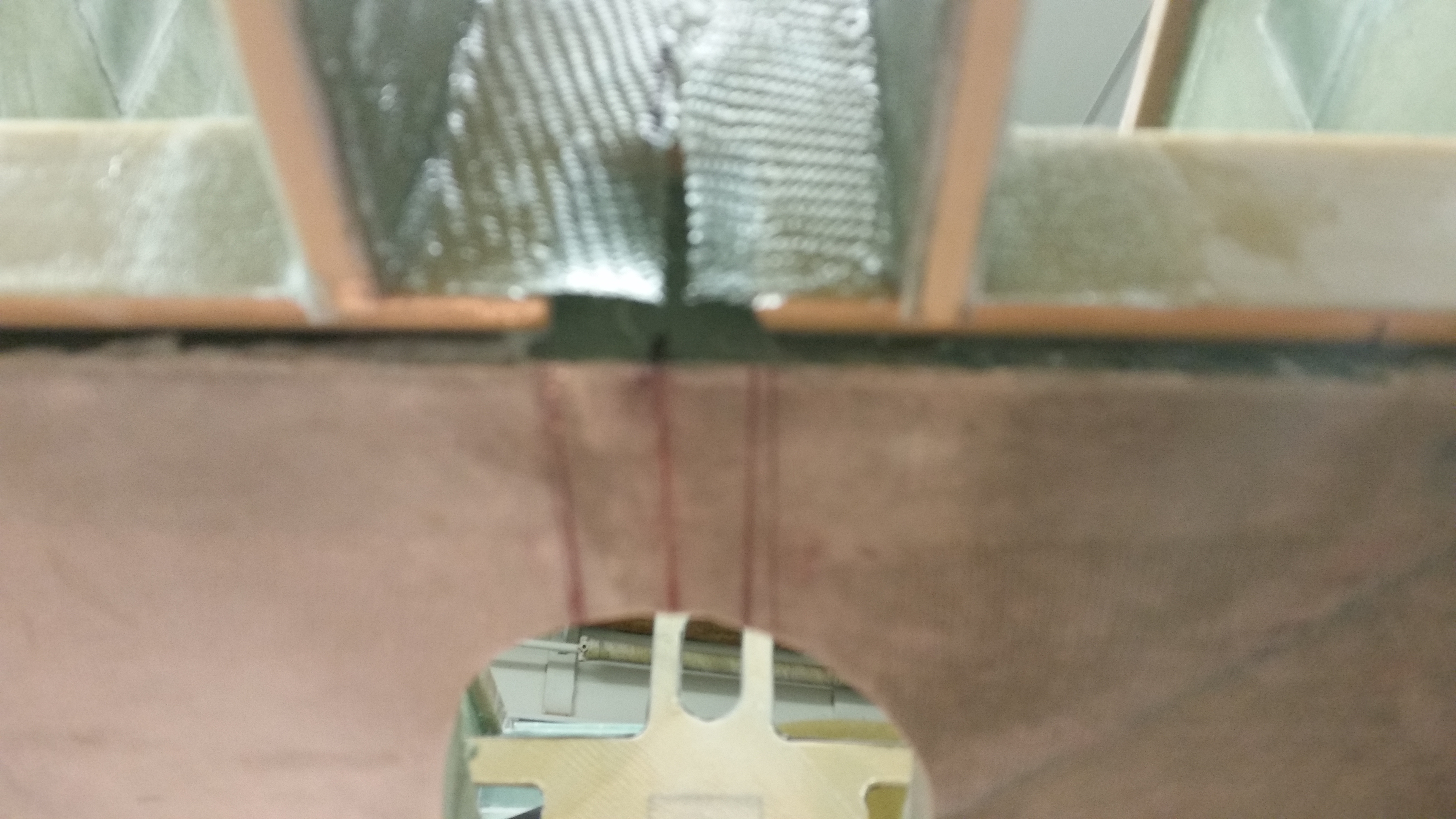
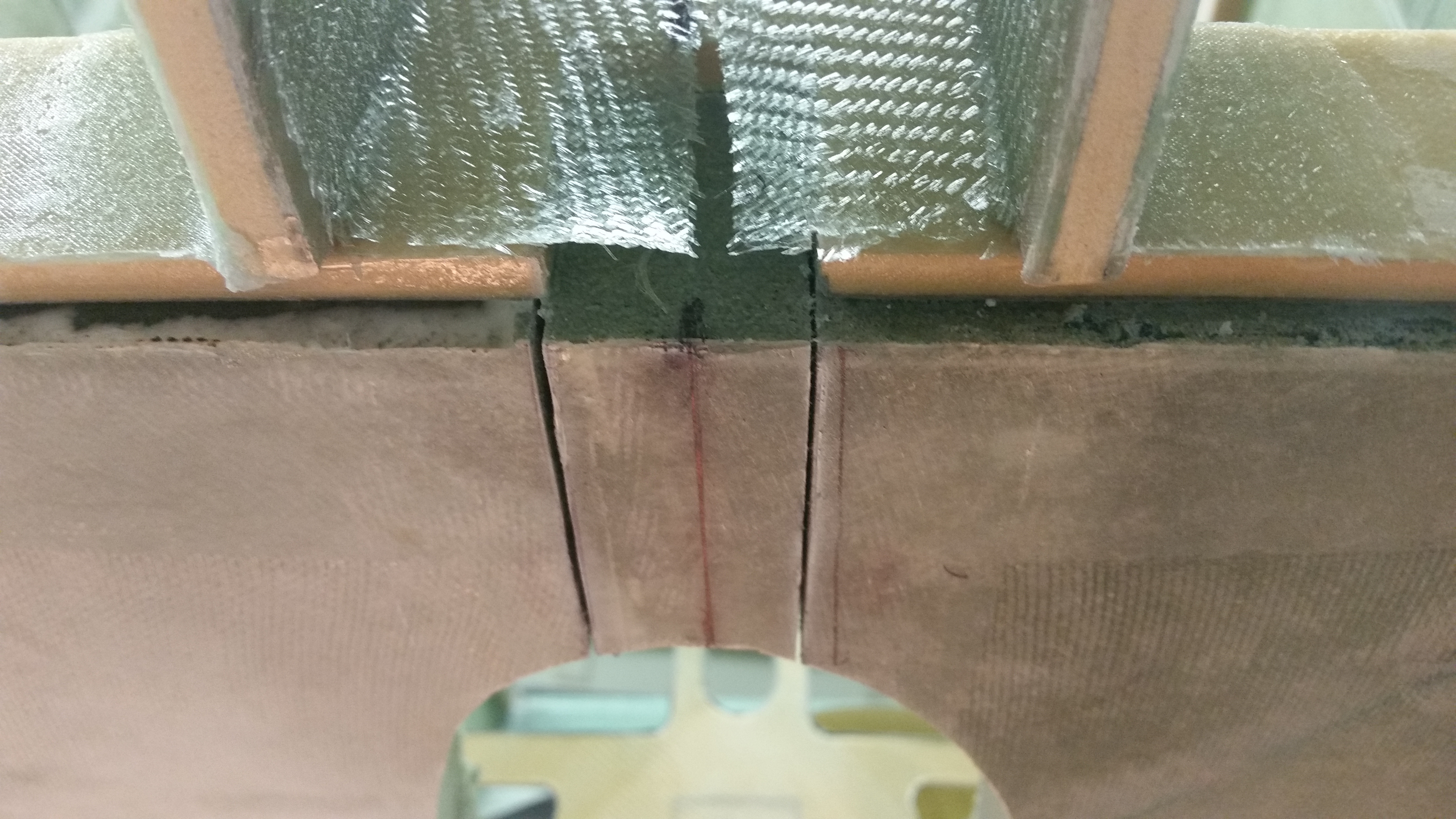
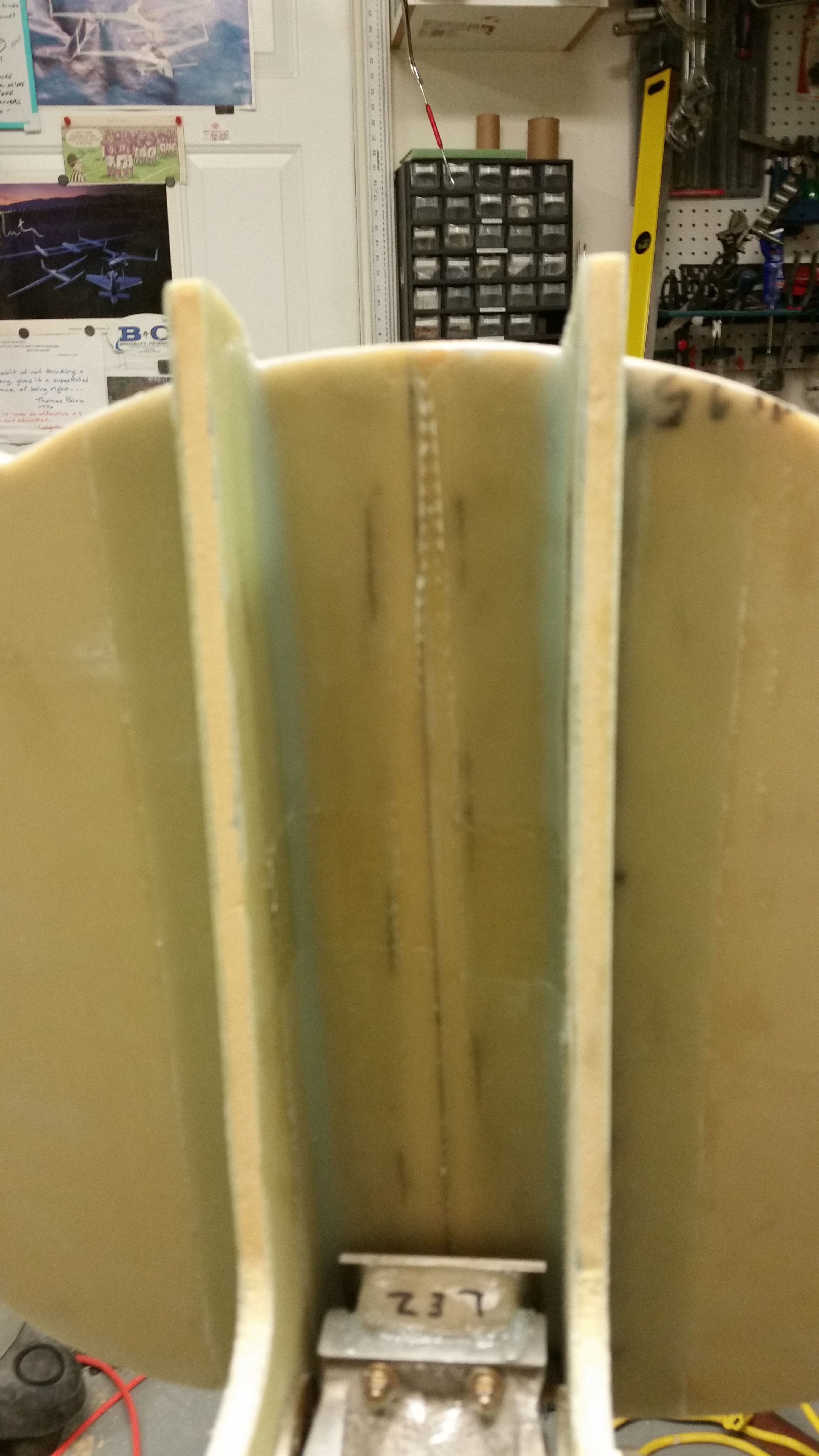
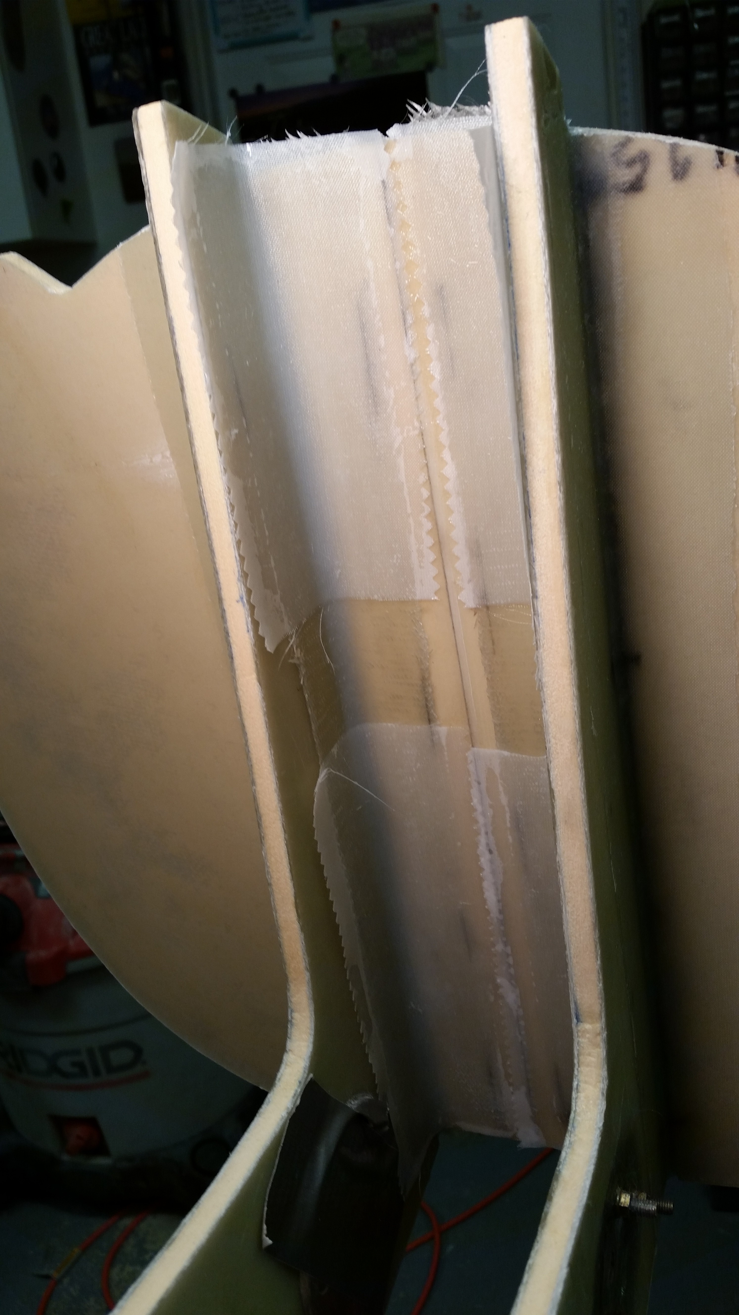
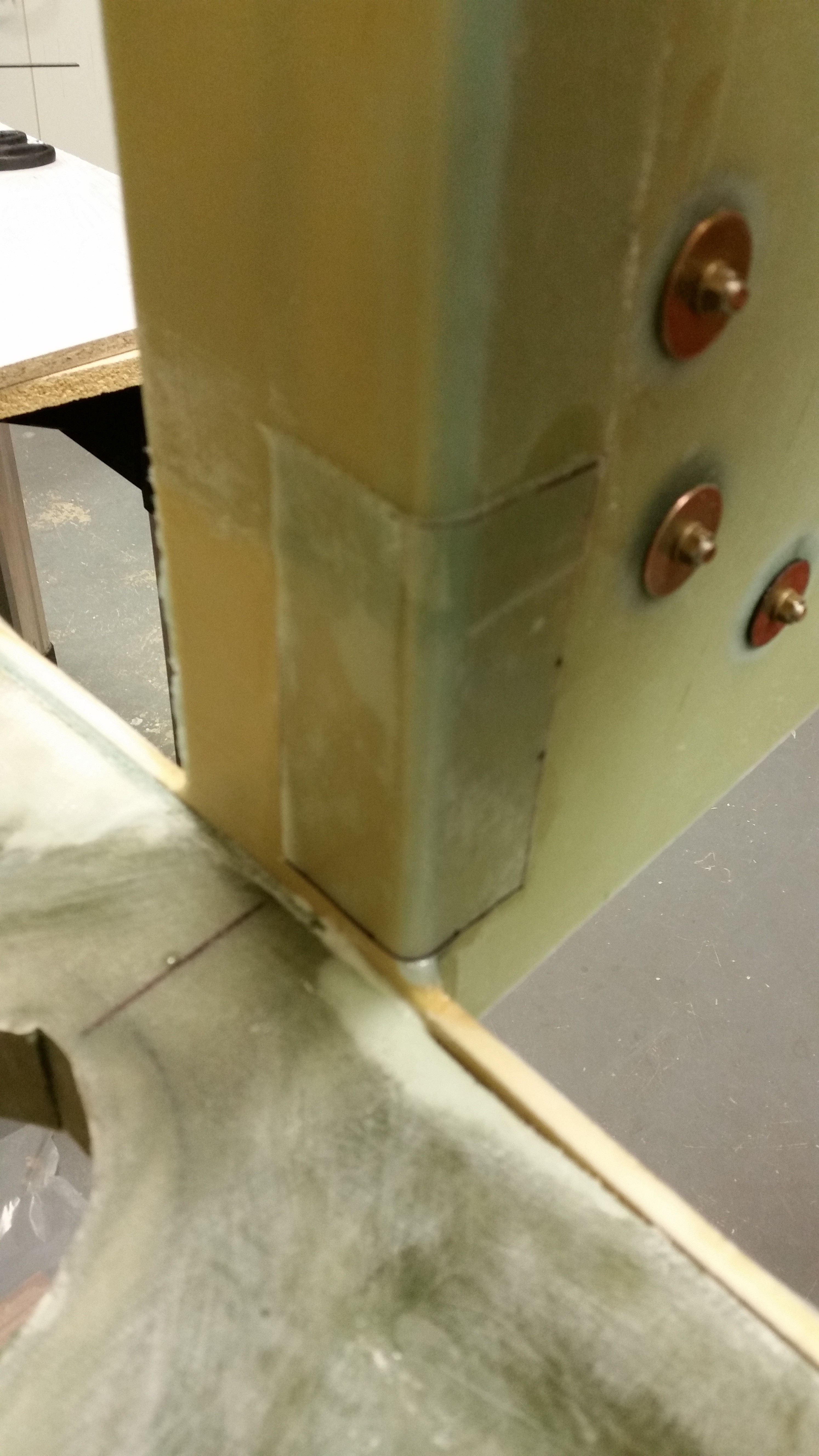
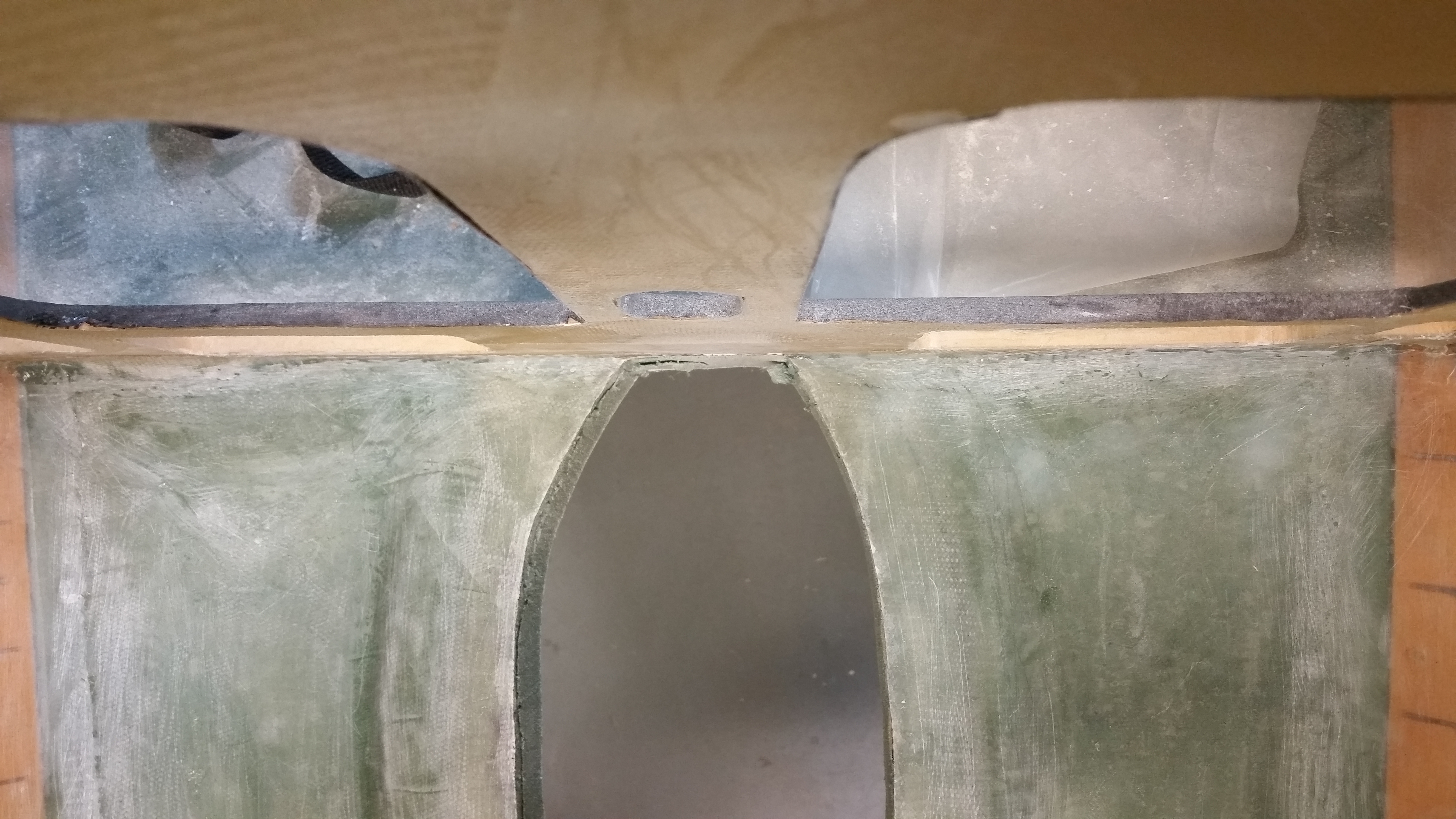
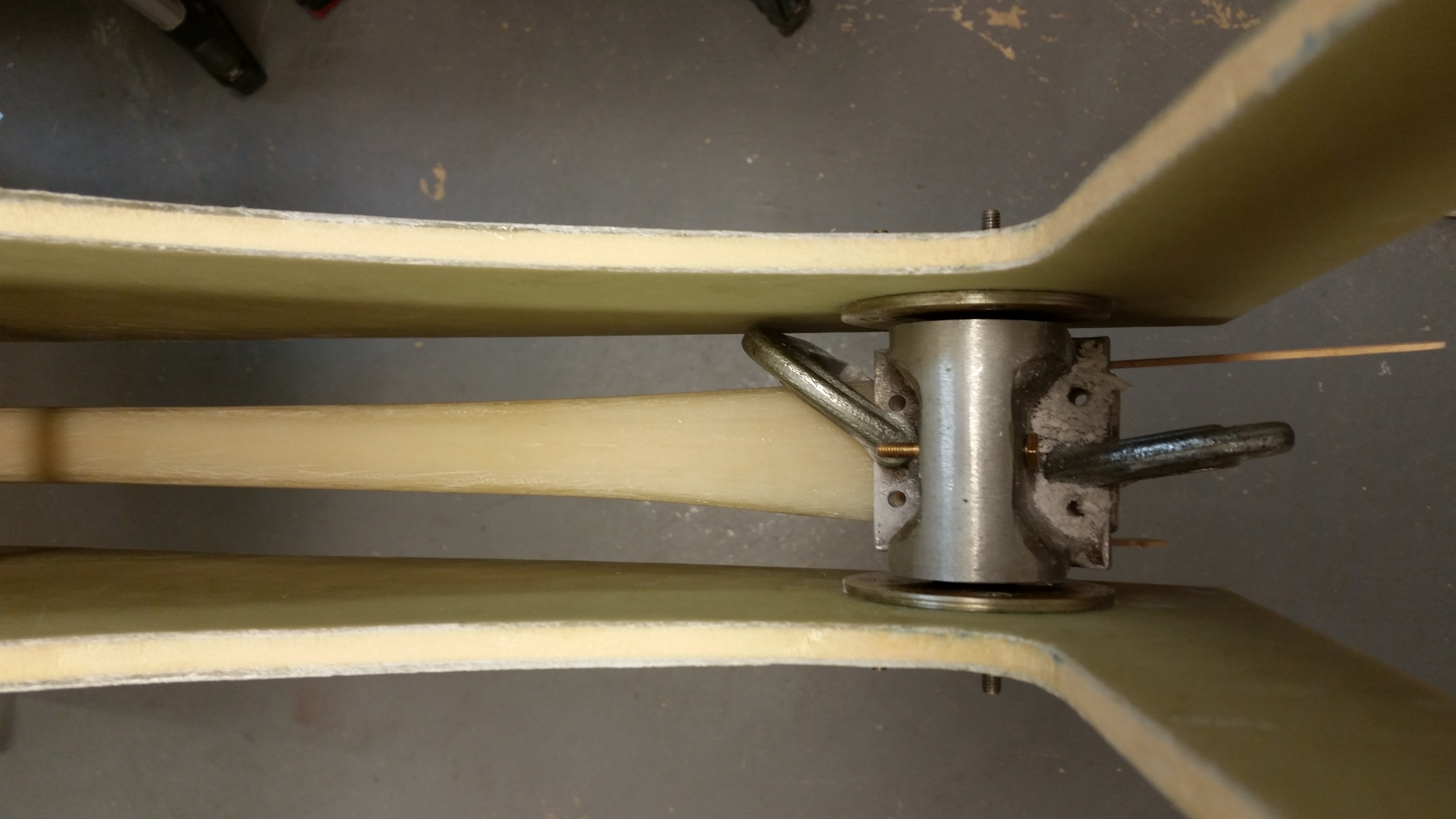
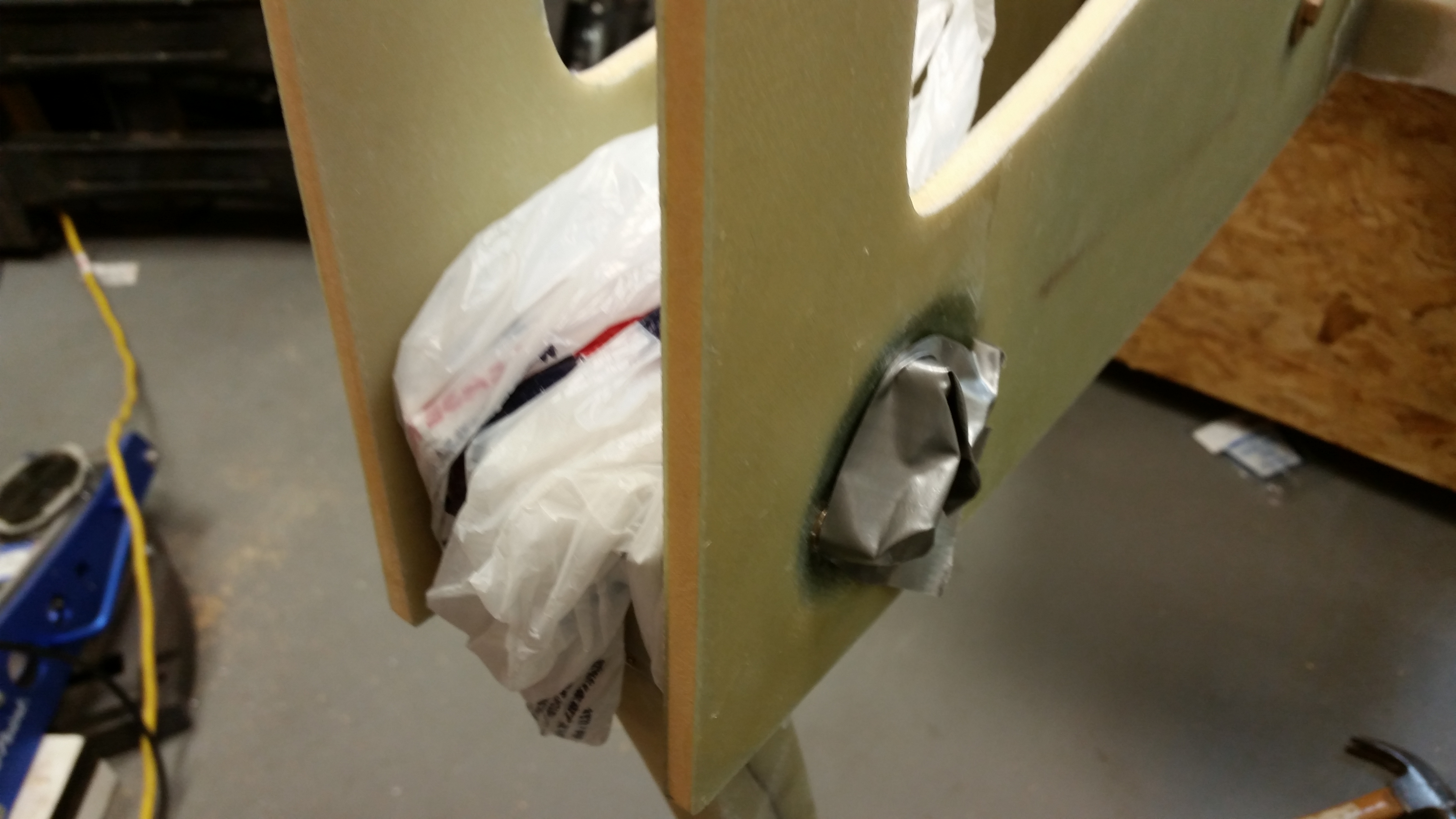
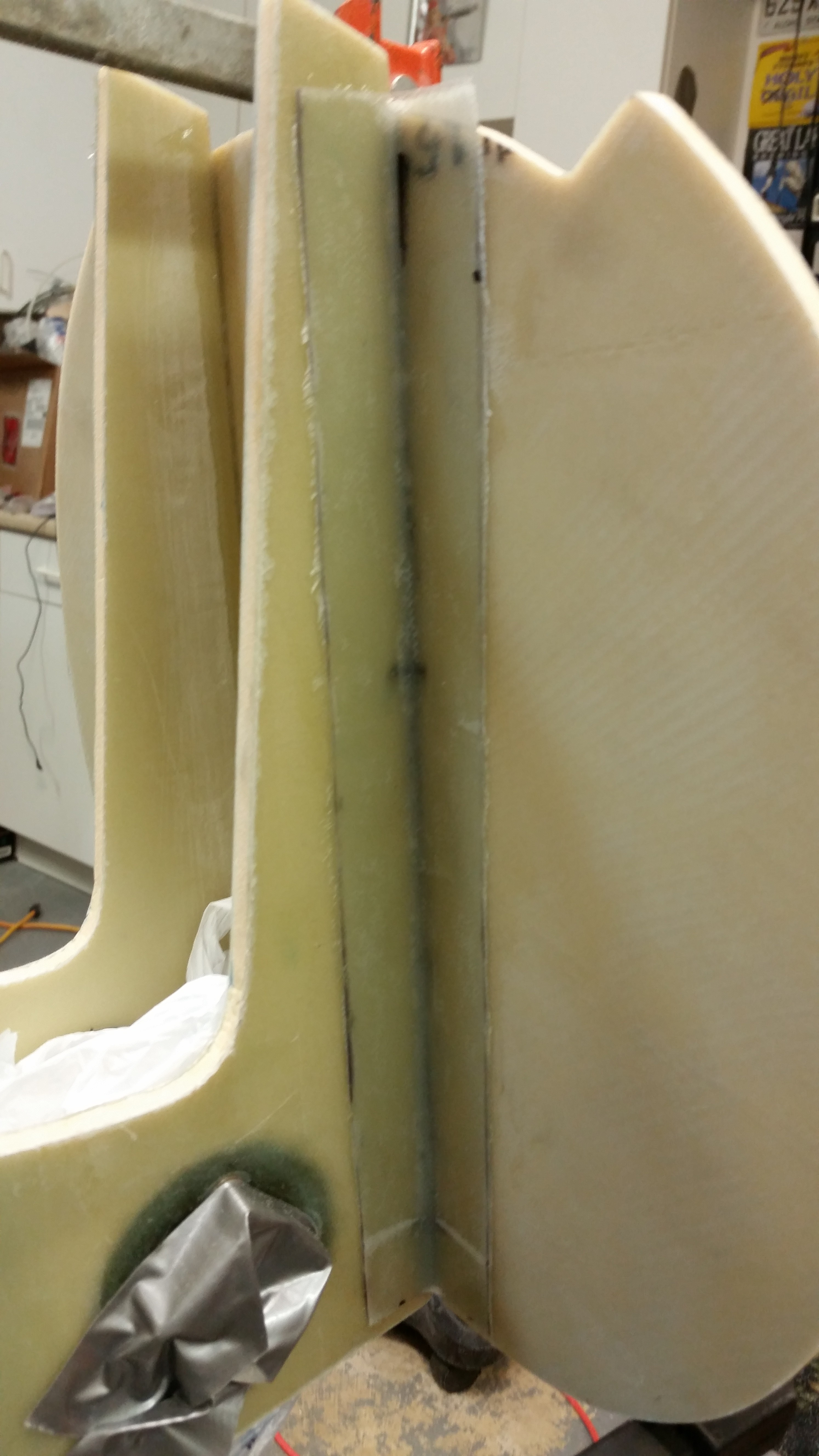
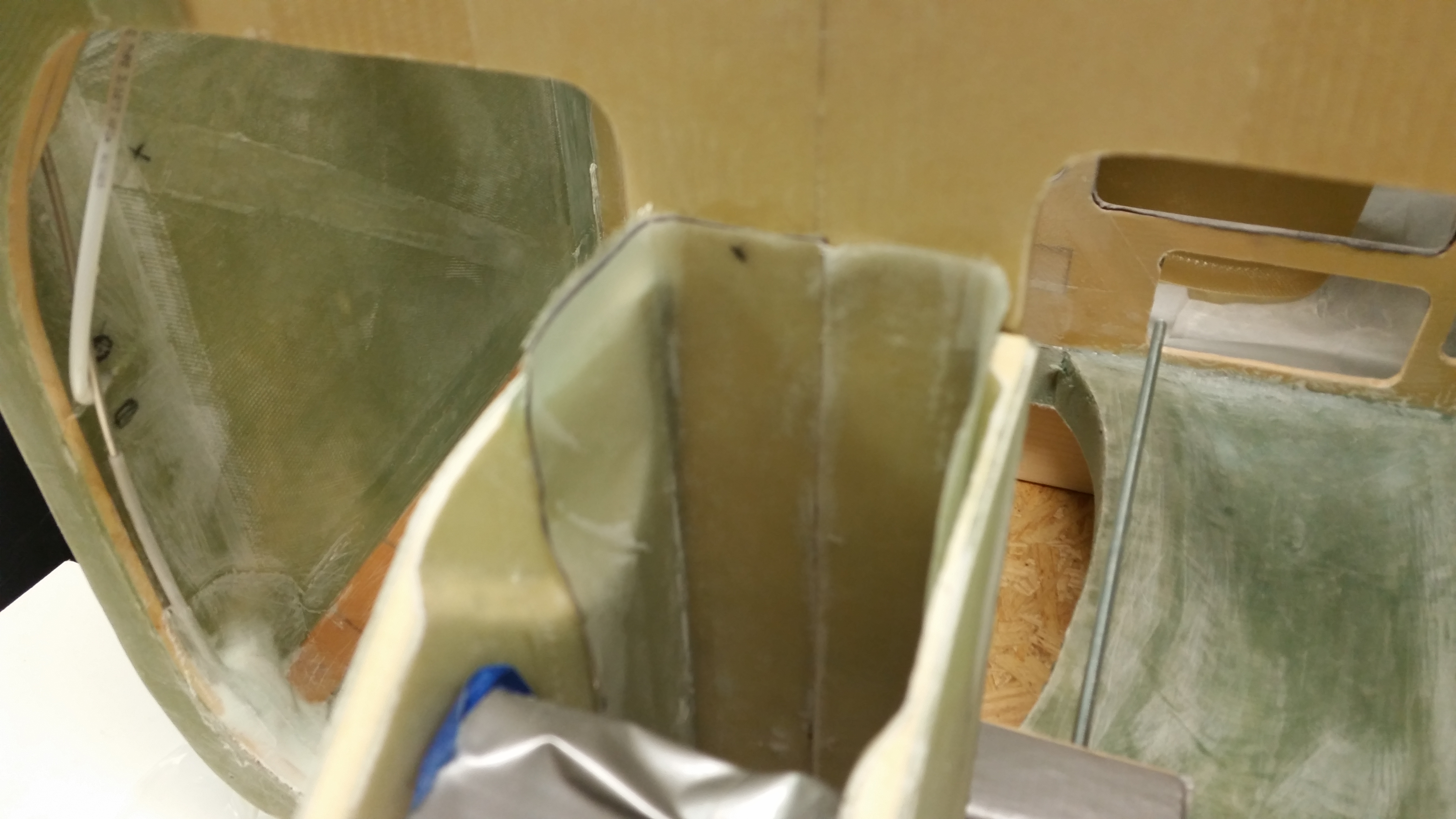
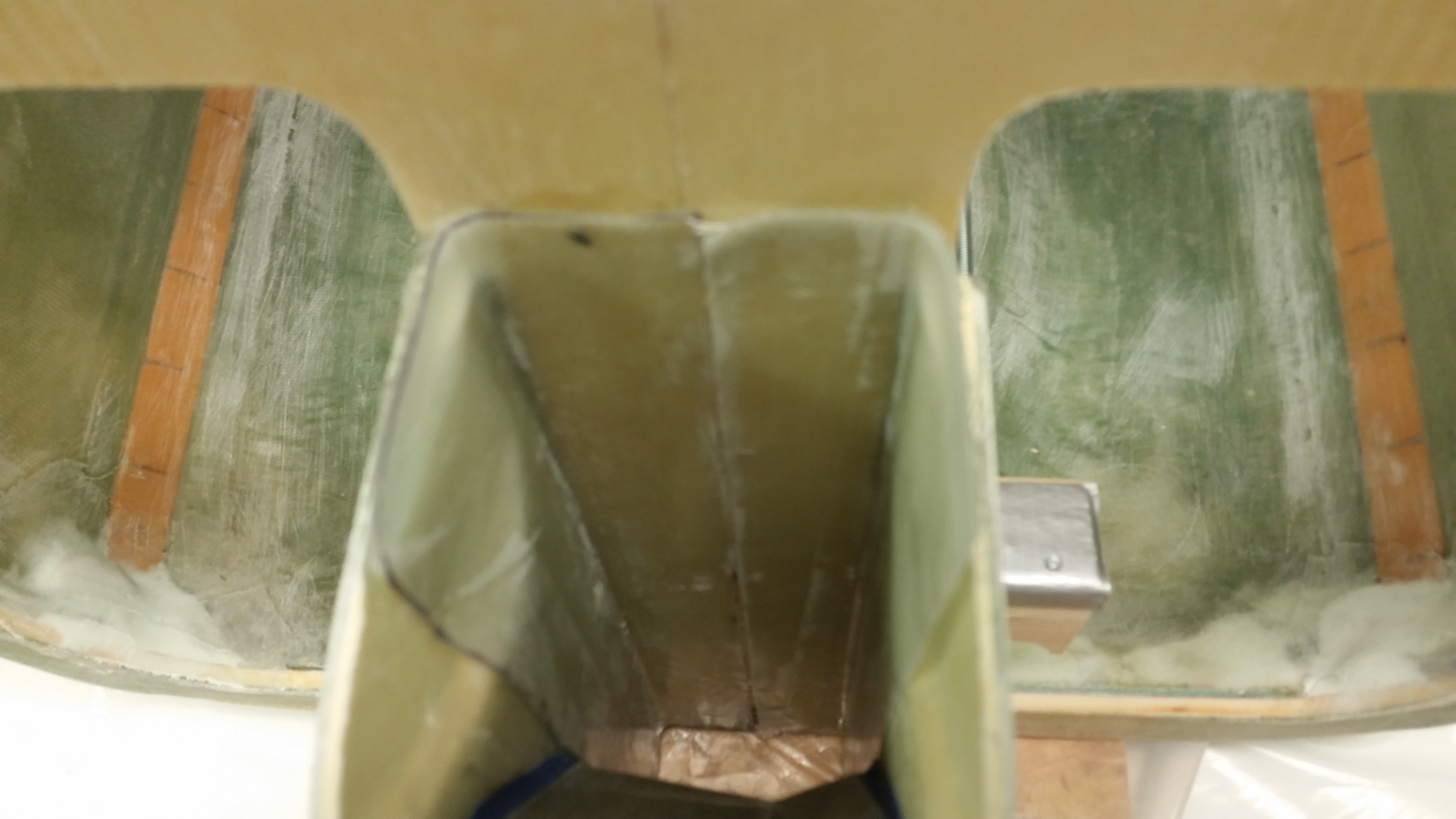
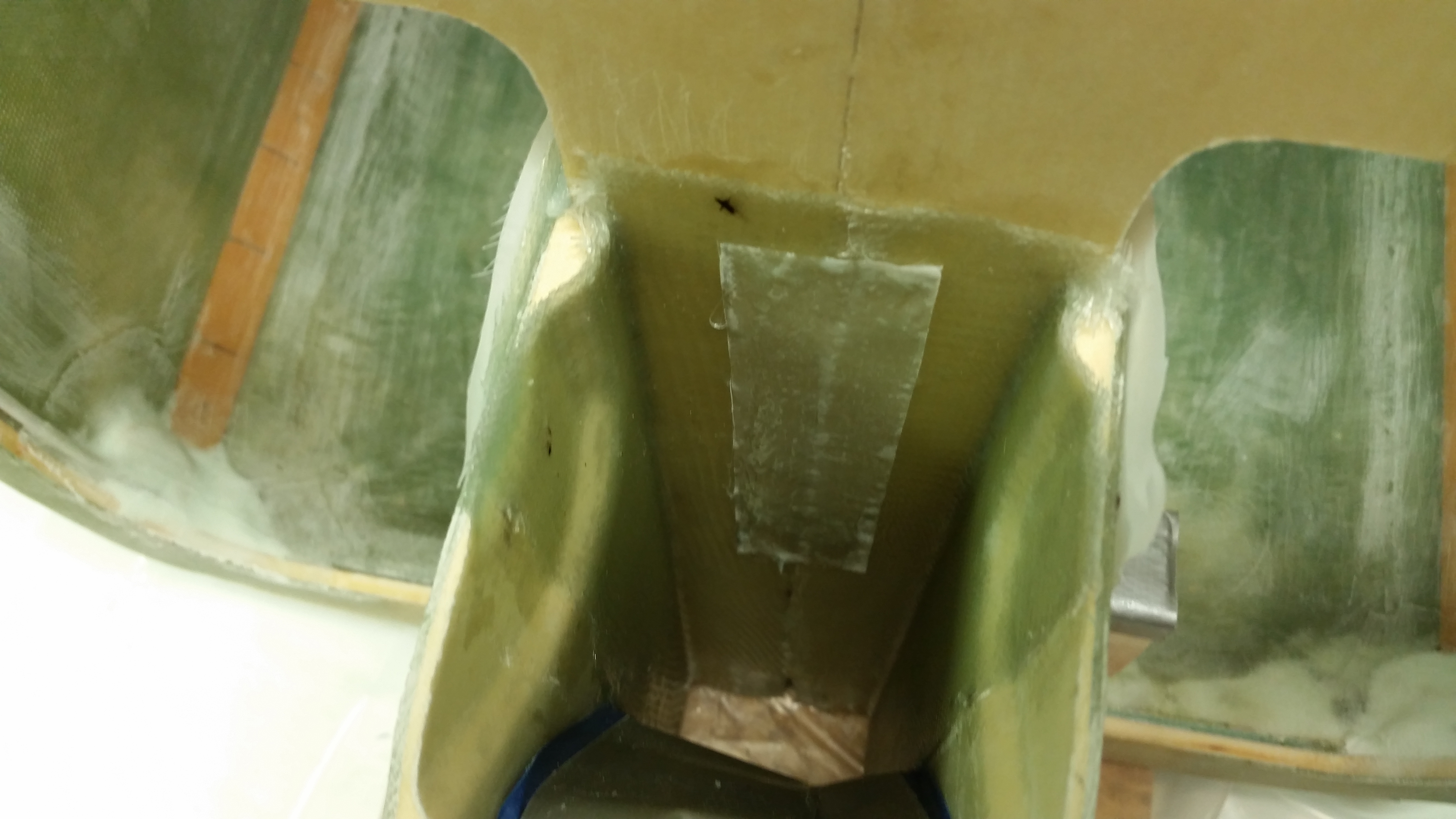
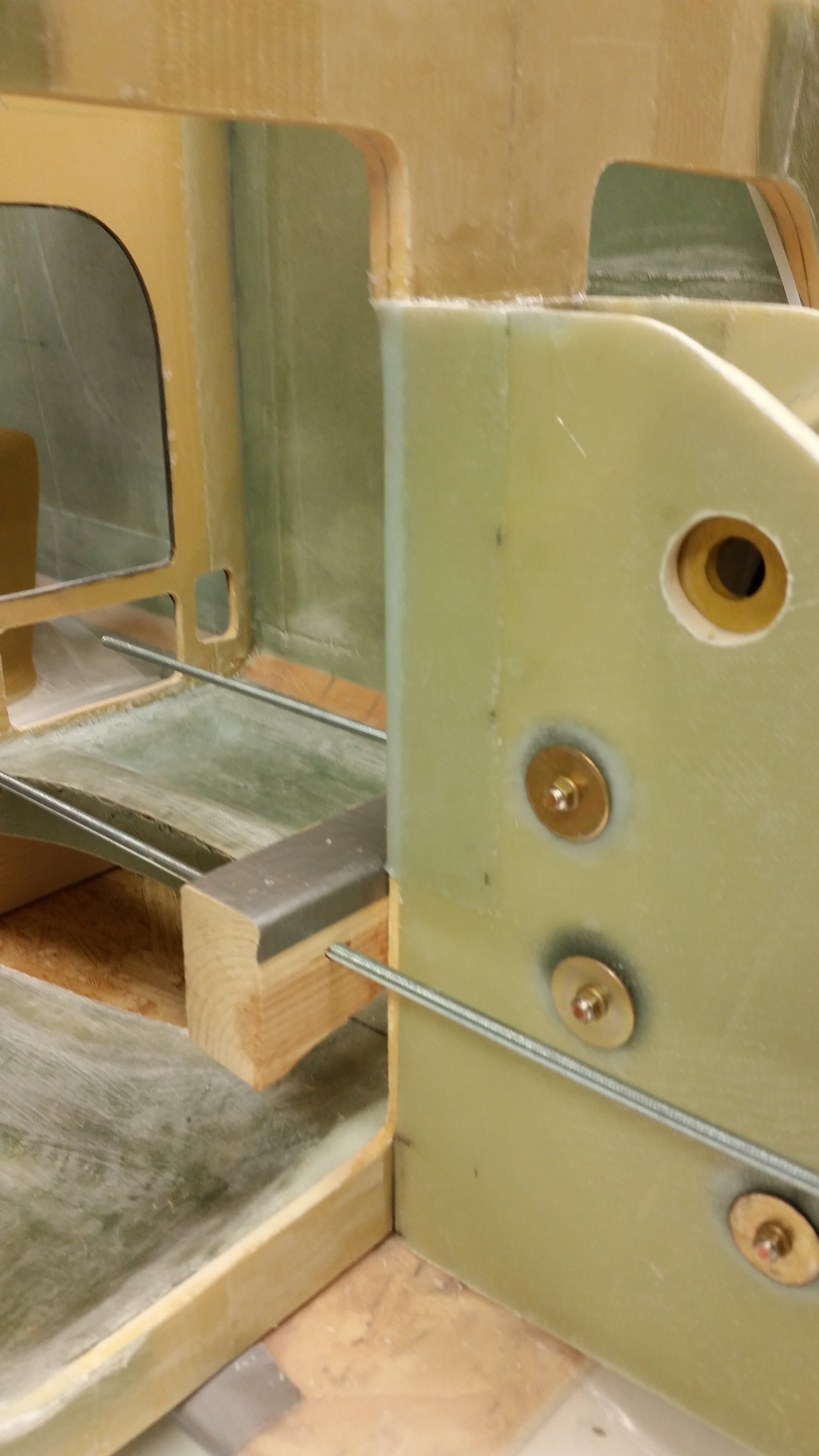
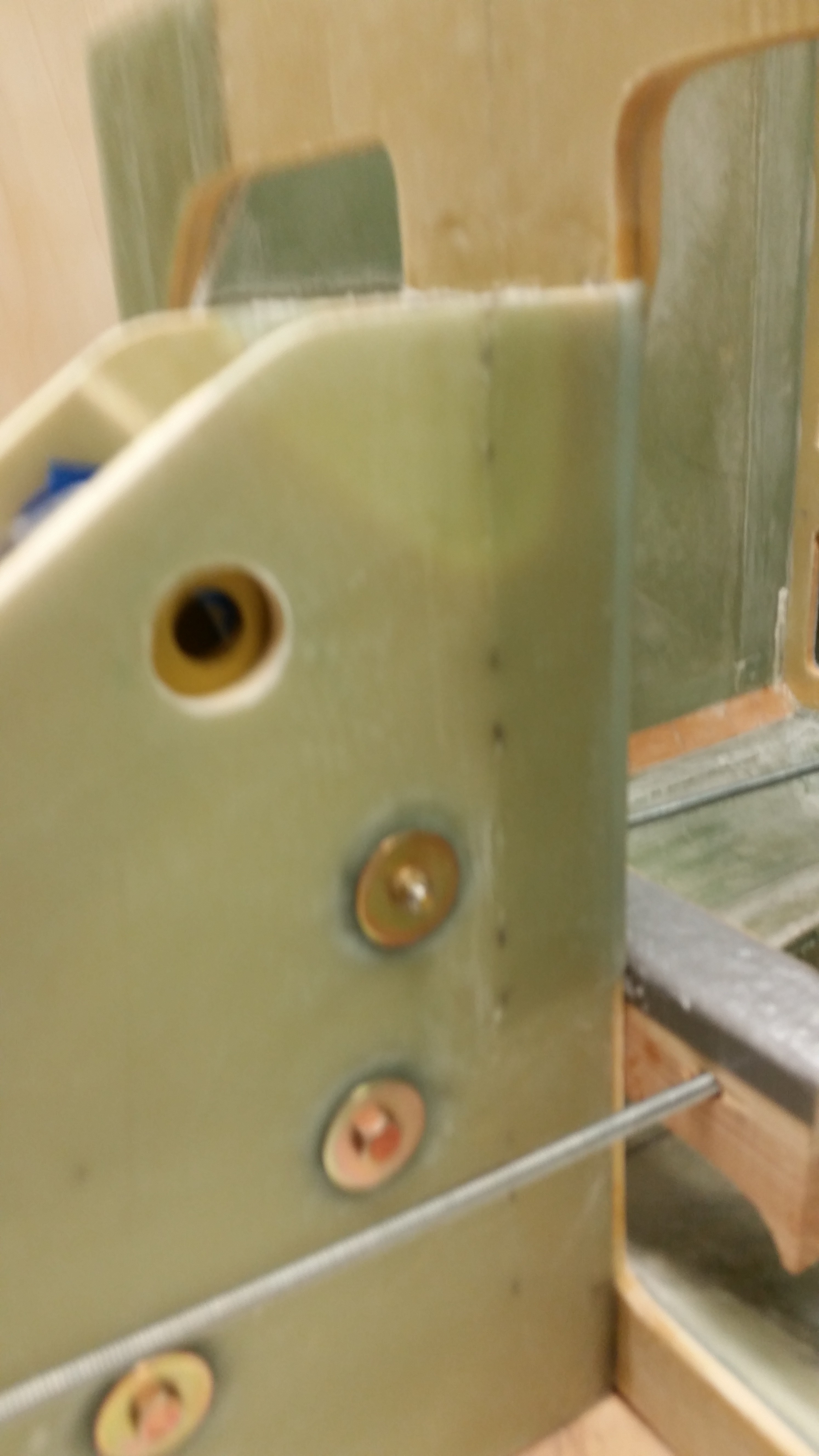
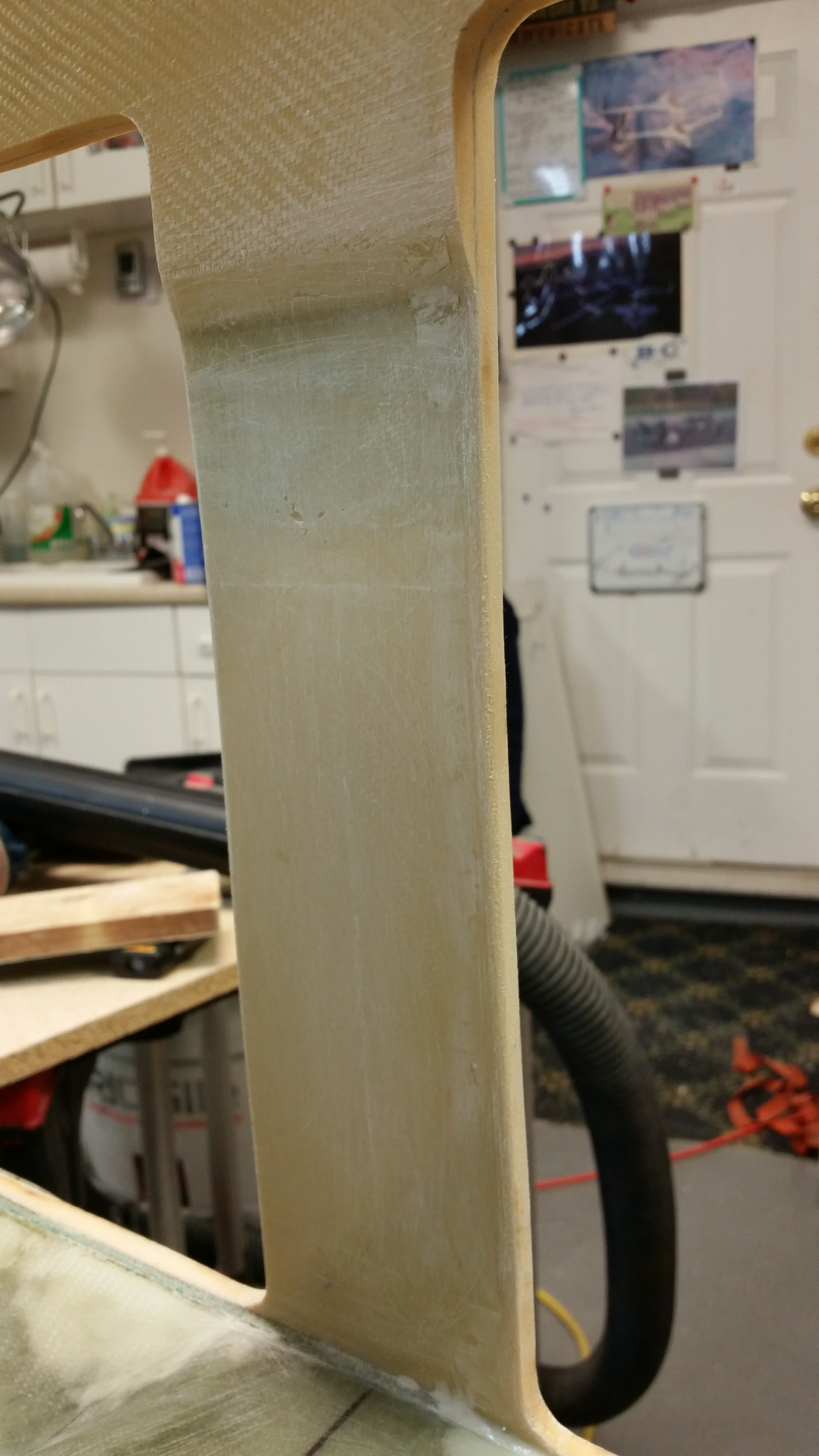
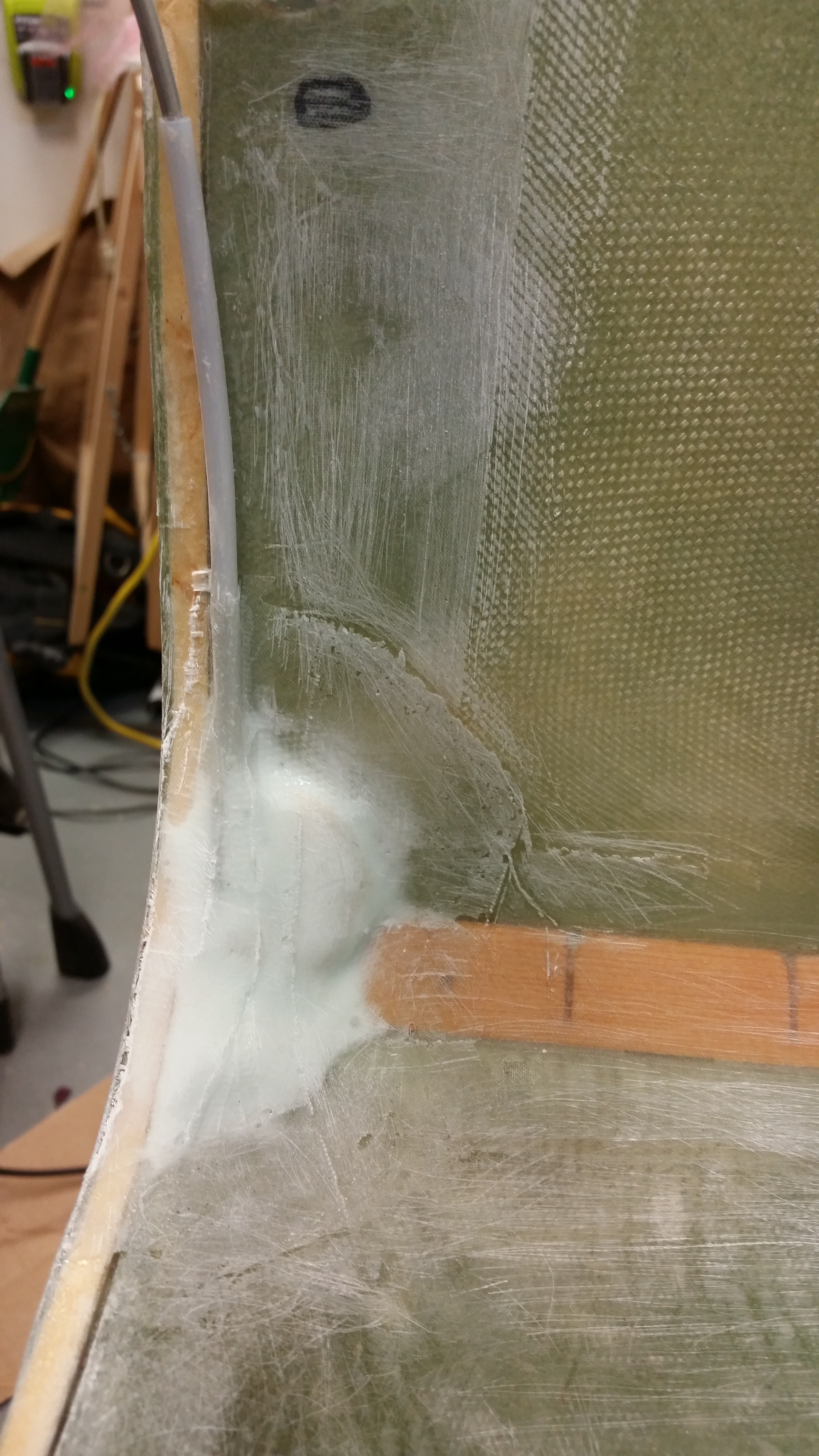
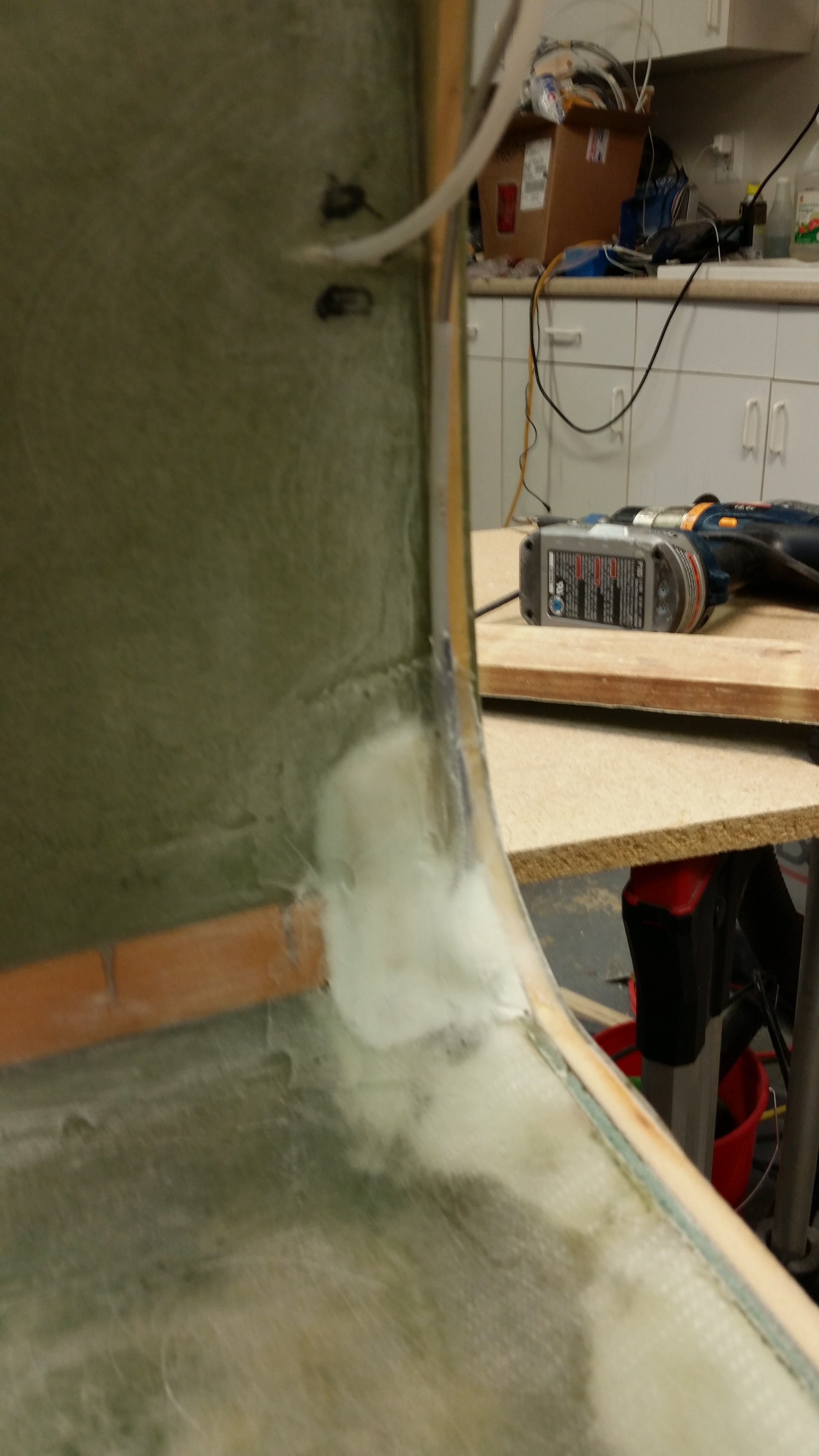
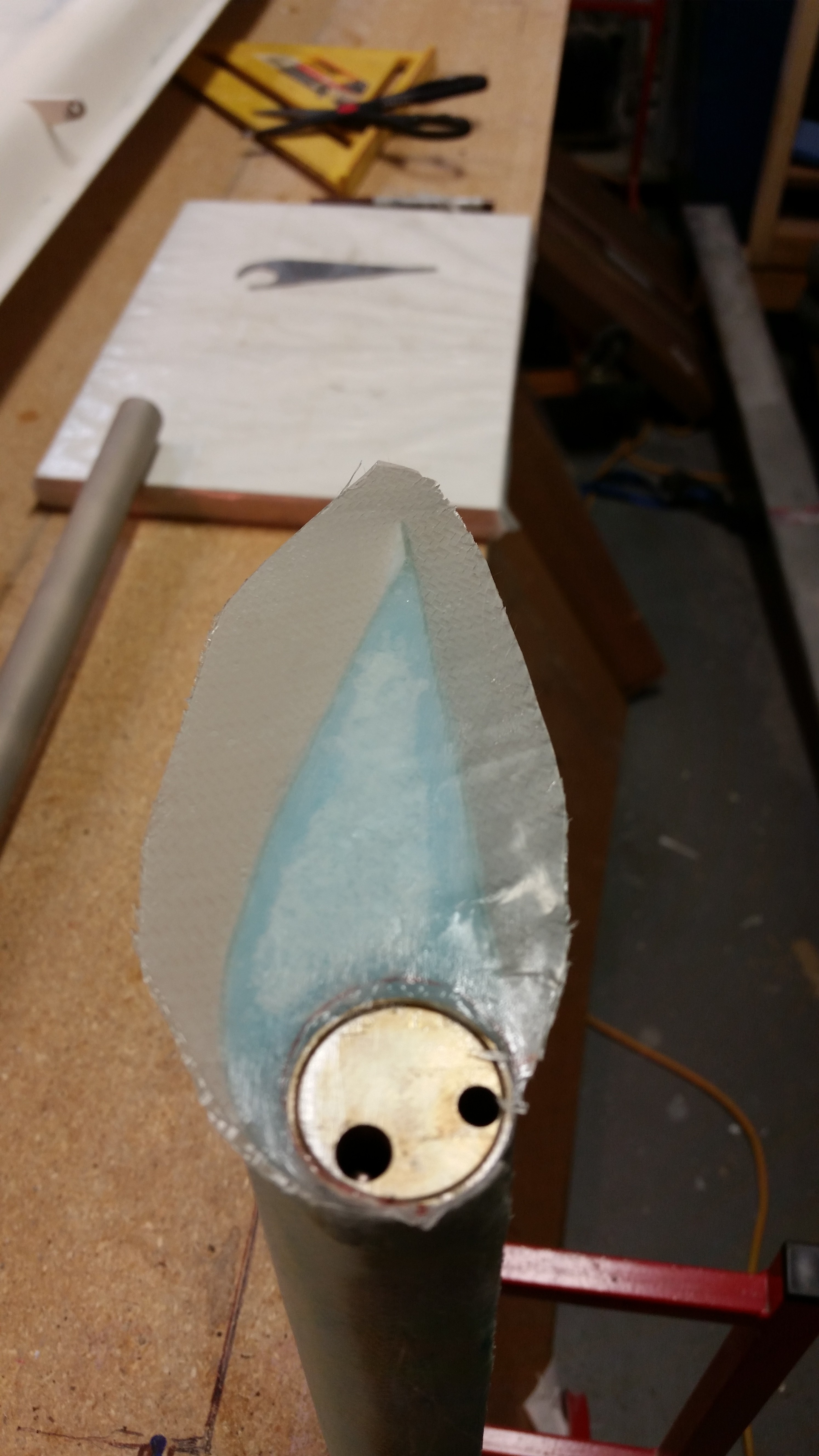
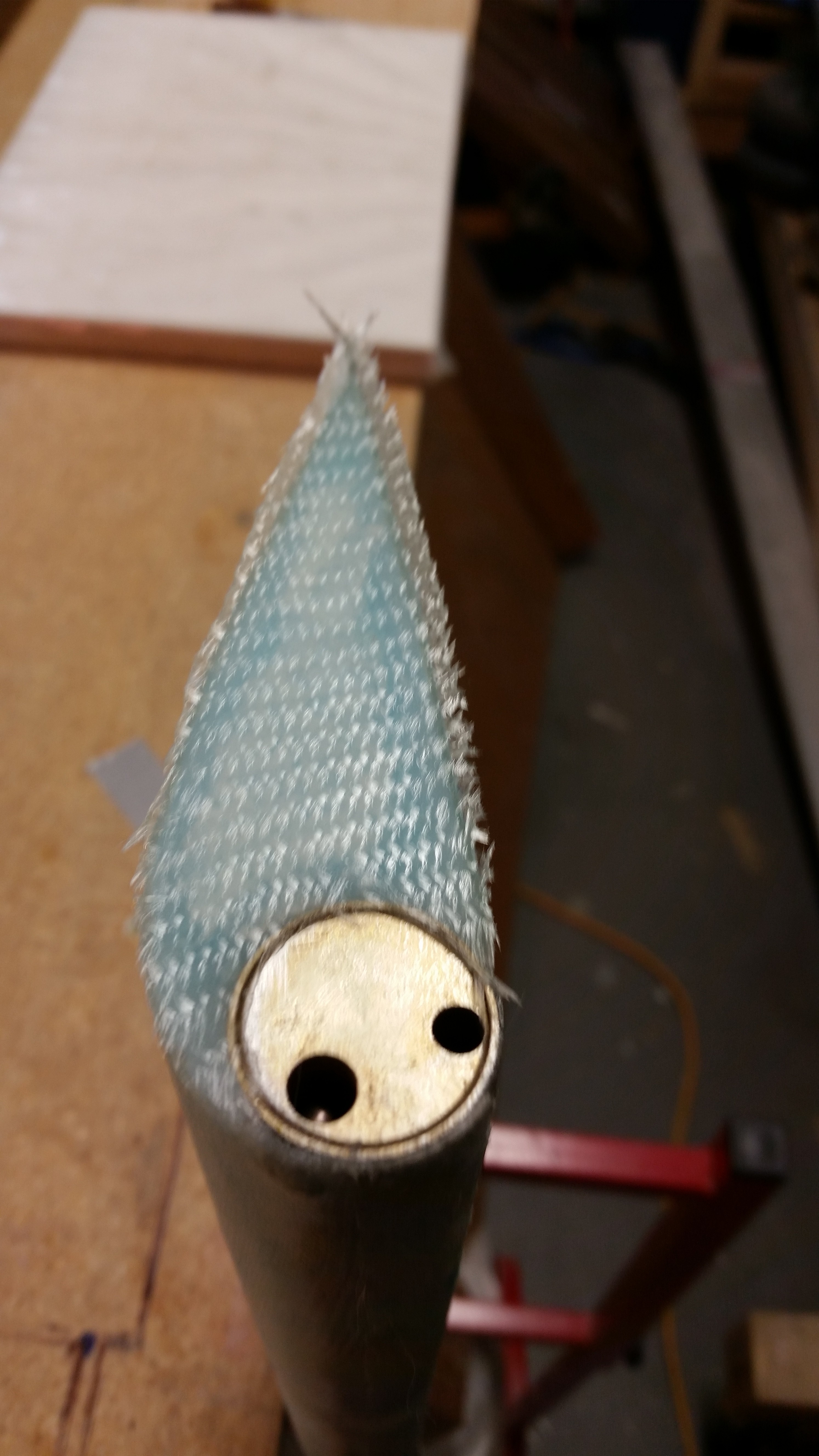
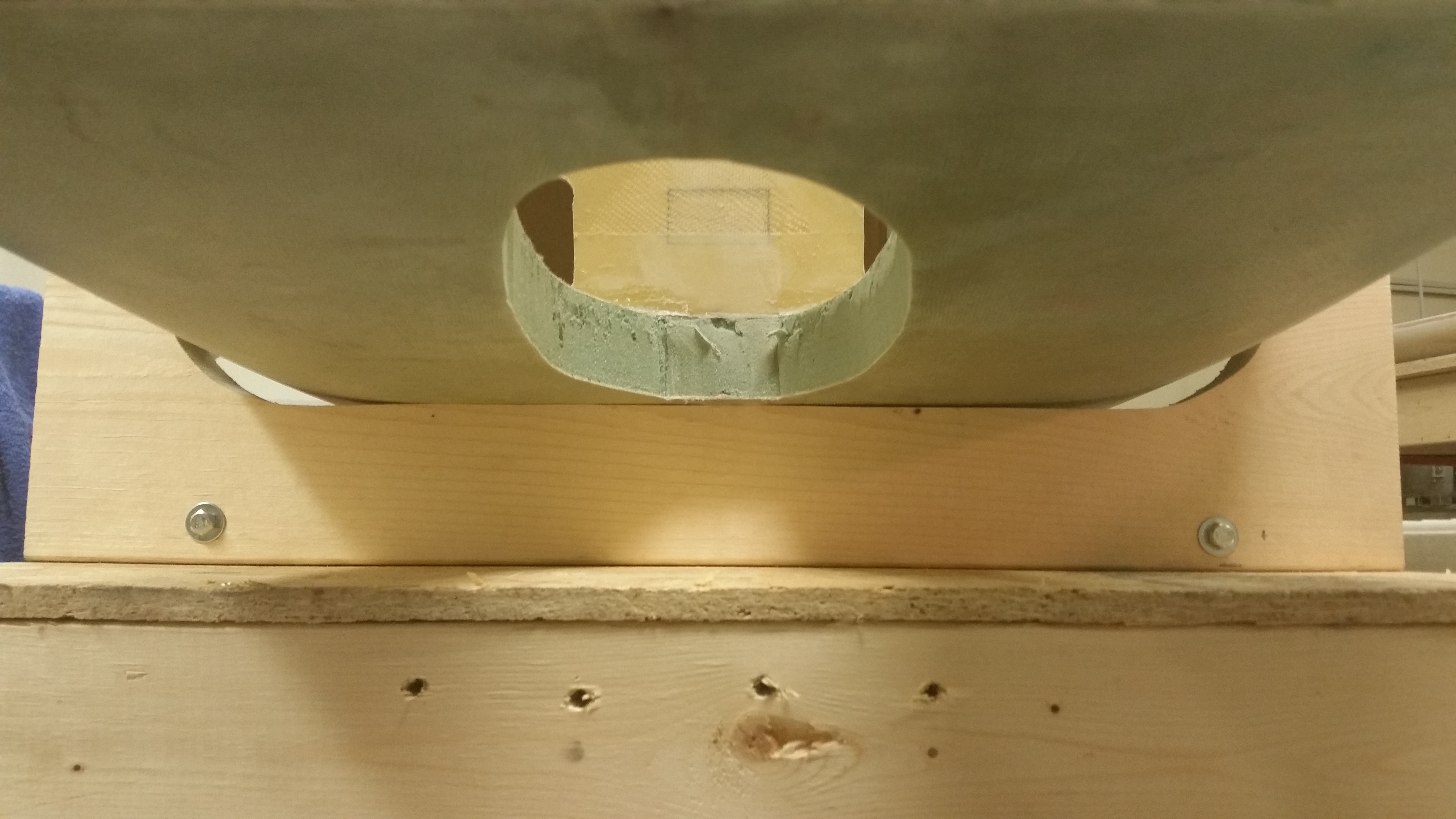
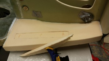
BTW, if you look in the pic below you can barely make out the gap in the junction between the front of the sidewall foam & the F1-3 bulkhead, aka Napster.

Mocking up rudder pedal fit

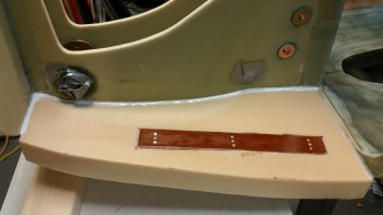
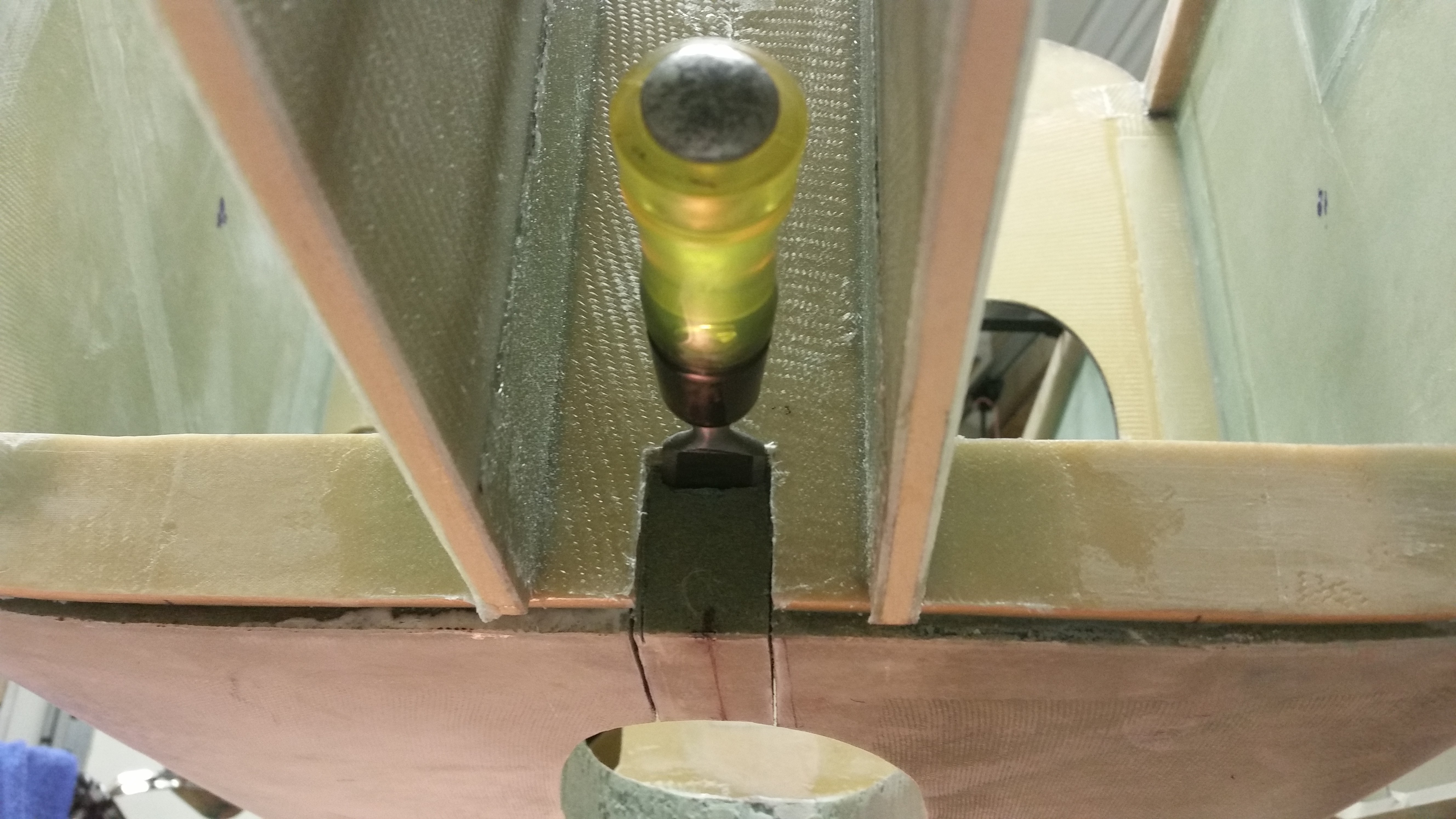
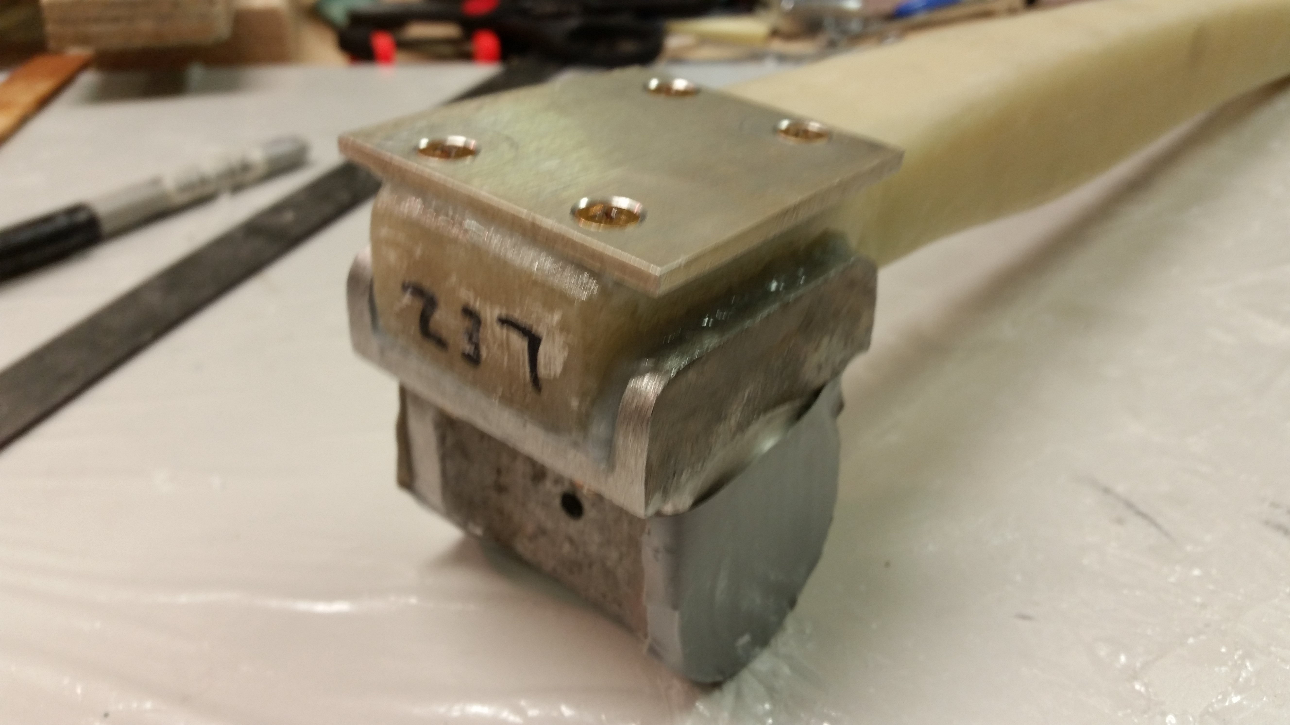
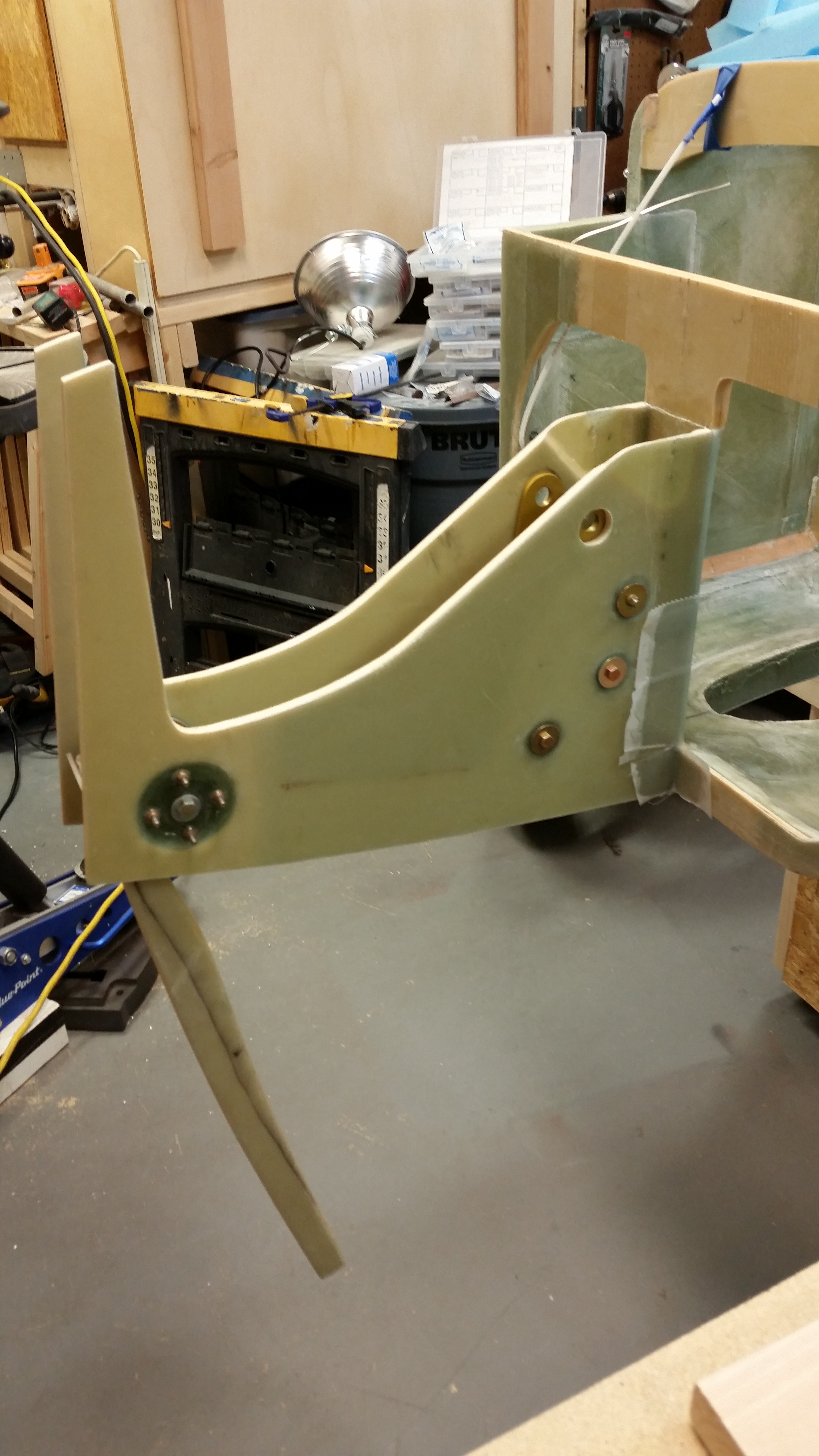
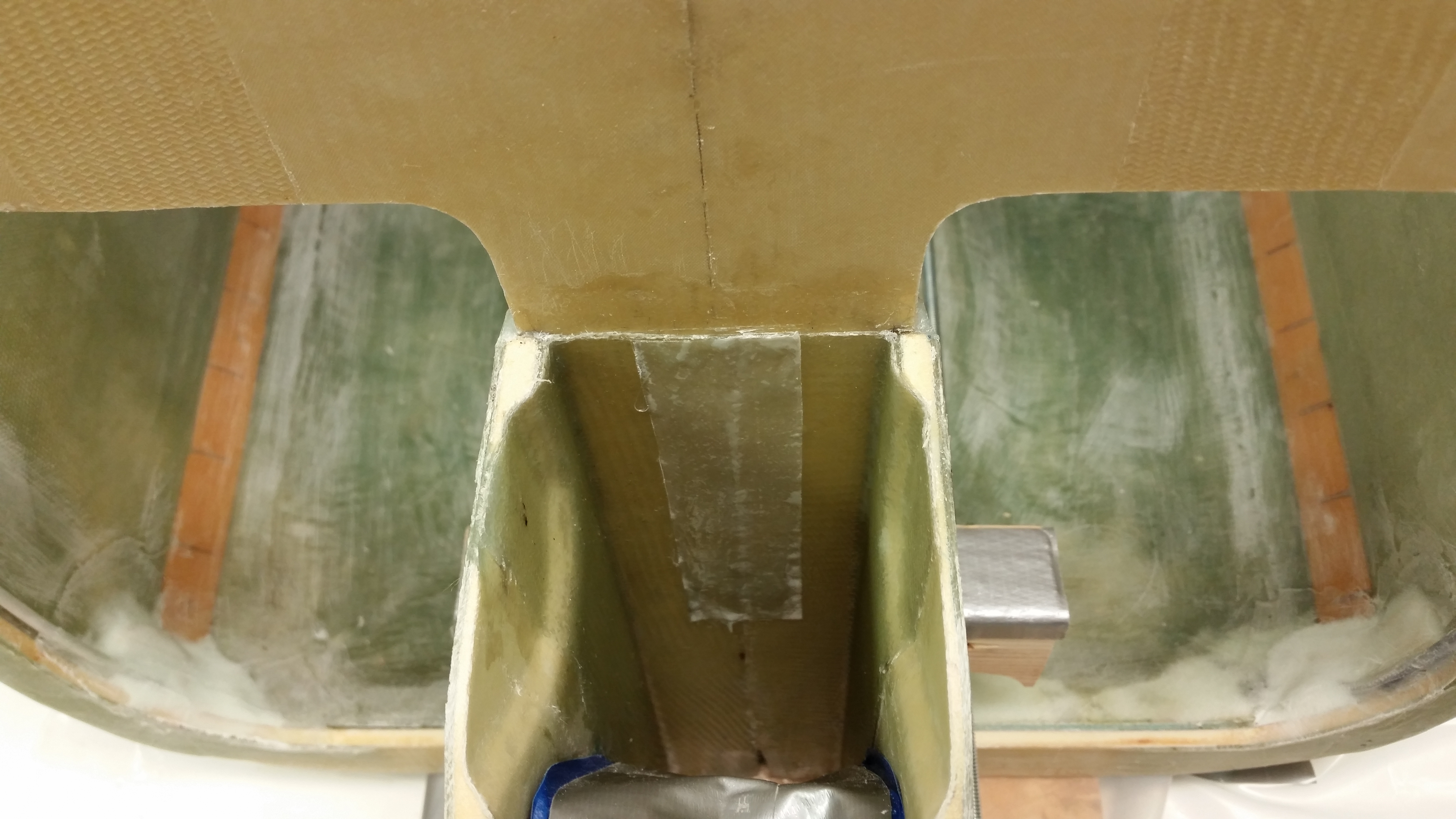
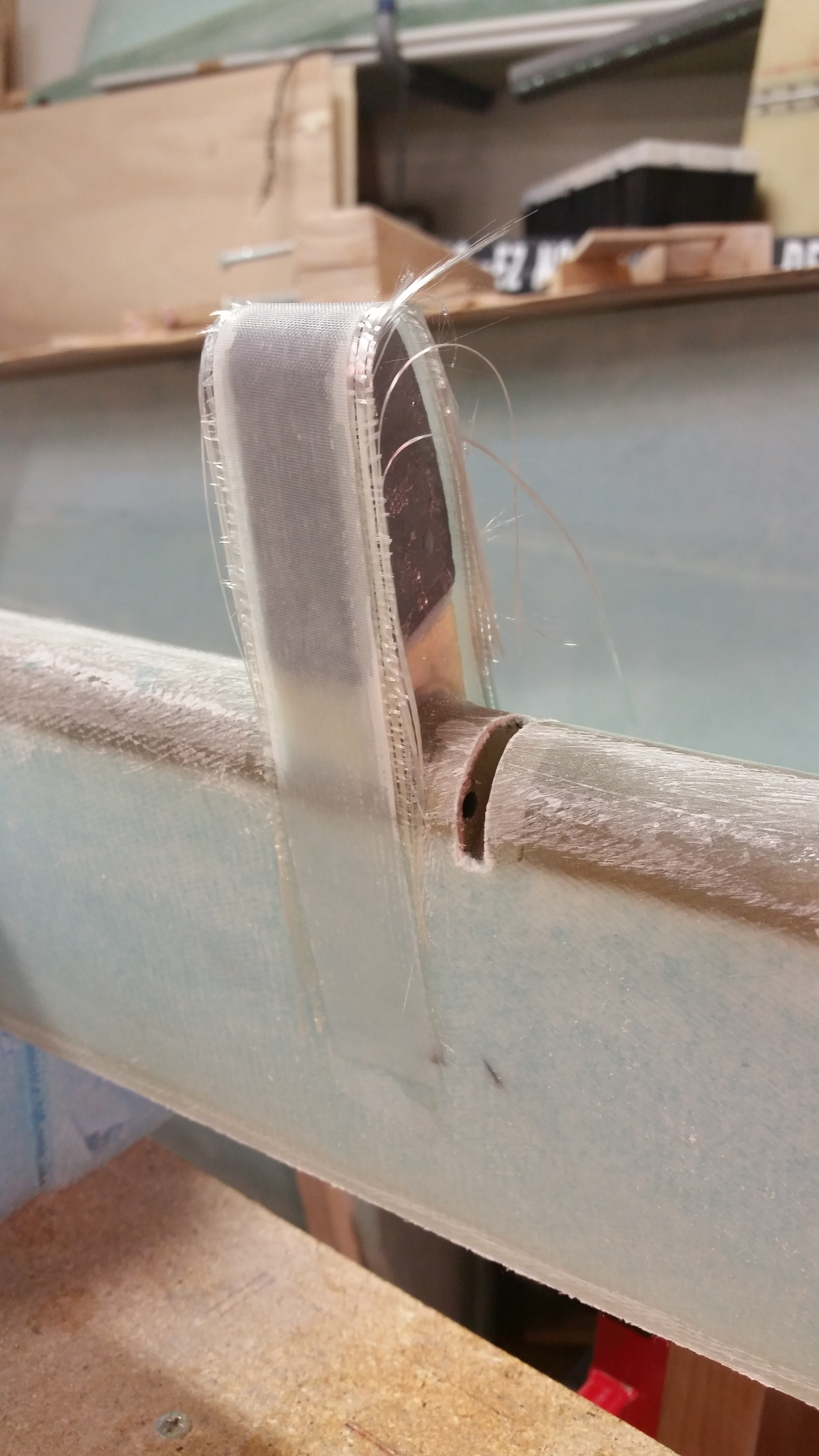
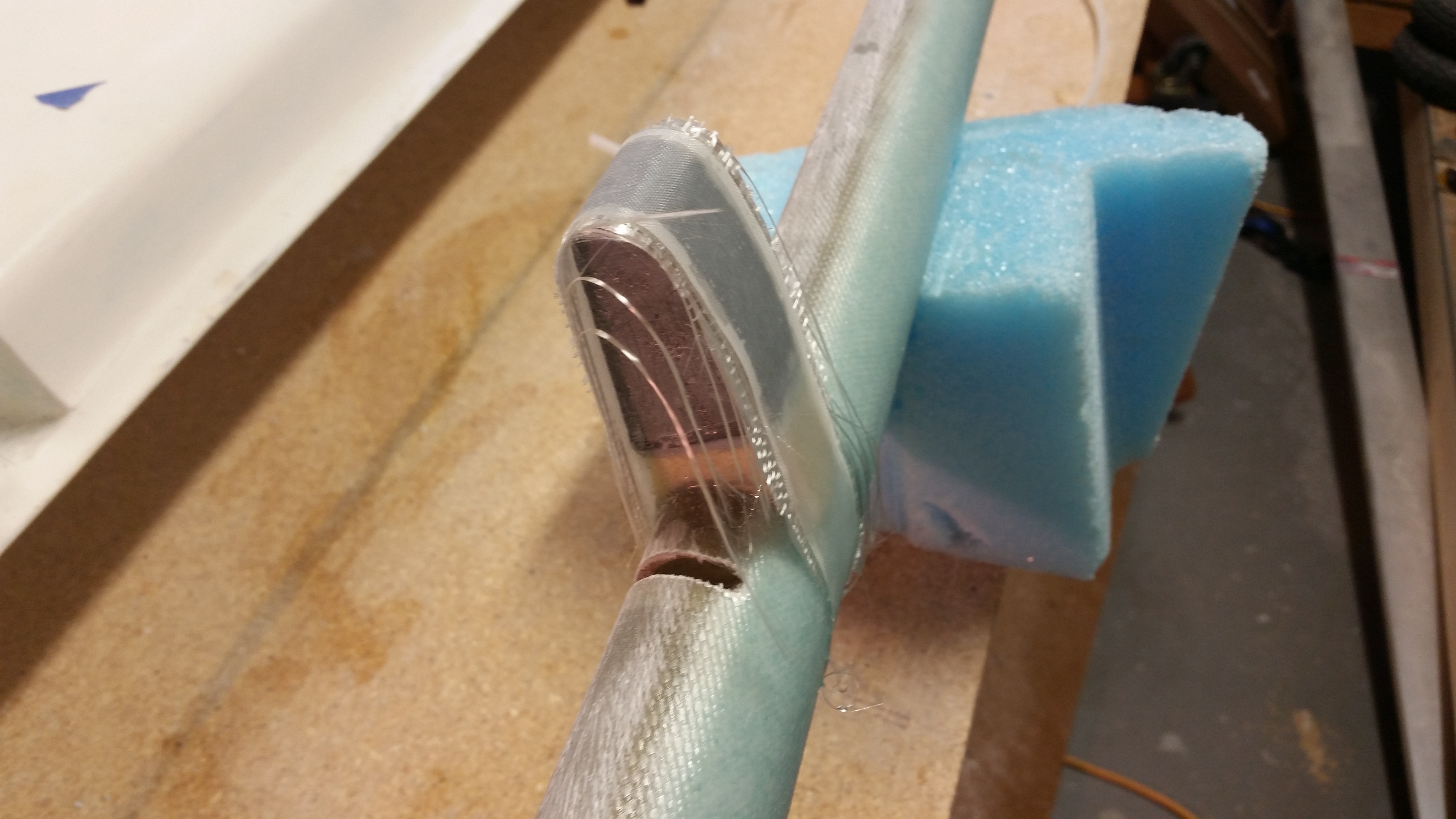
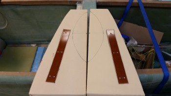
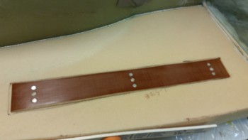
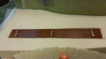
With compromises on side clearances made with the rudder pedals, and thus the mounting location on the floor pans pinpointed, I marked around the perimeter of each phenolic pedal base (that comes with 3 x K1000-3 AN3- nutplates pre-installed…nice!). I then used my router to remove about 3/32″ of foam so that each base would lie perfectly flat with the top of the base level with the surface of the foam, allowing a minor clearance for application of micro as well.

Rudder pedal base mounts routered

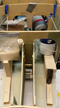
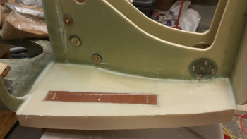
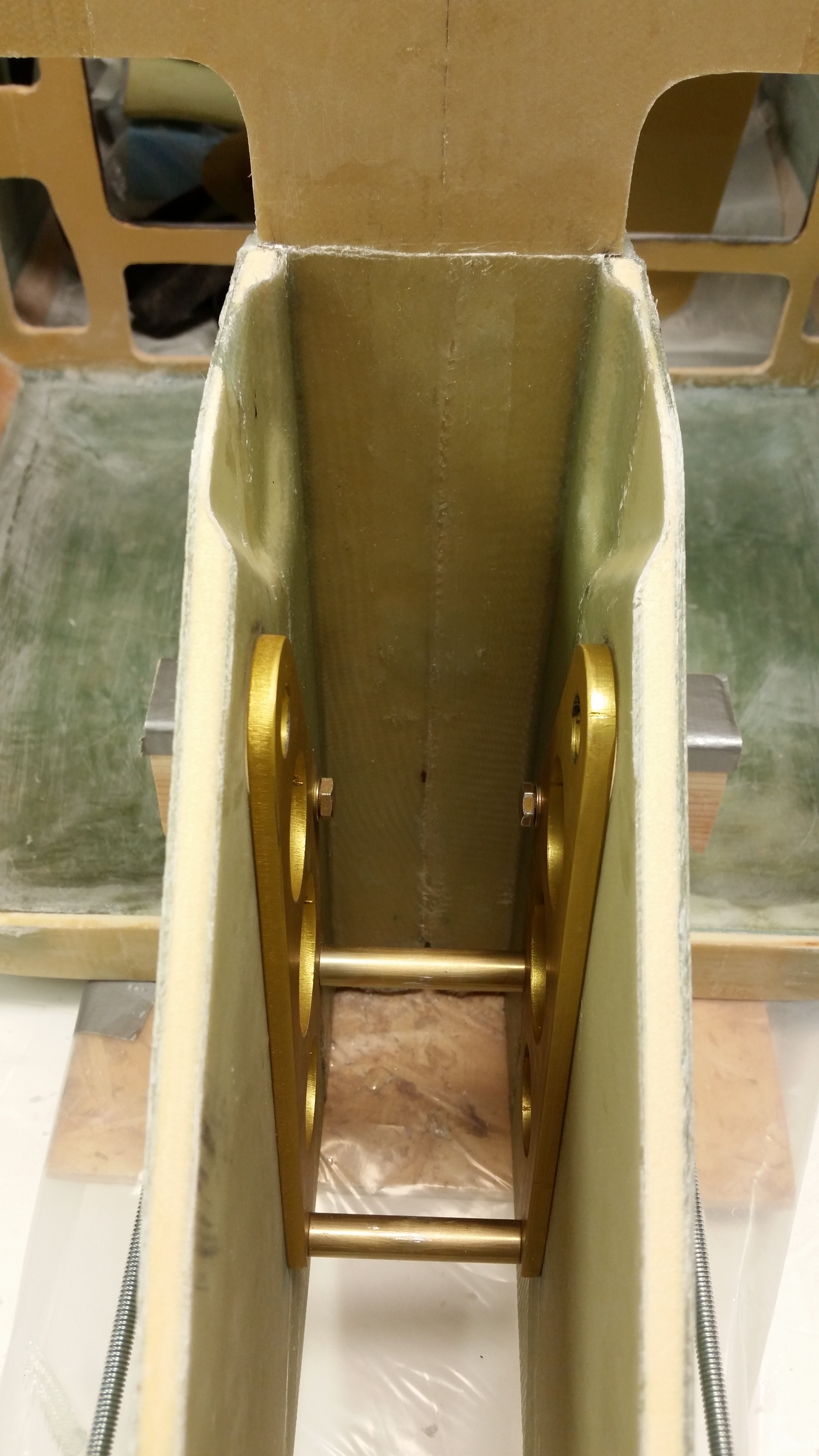
Here are the pedal bases fitted in the their mounting recesses in the foam.

Checking rudder pedal base fit

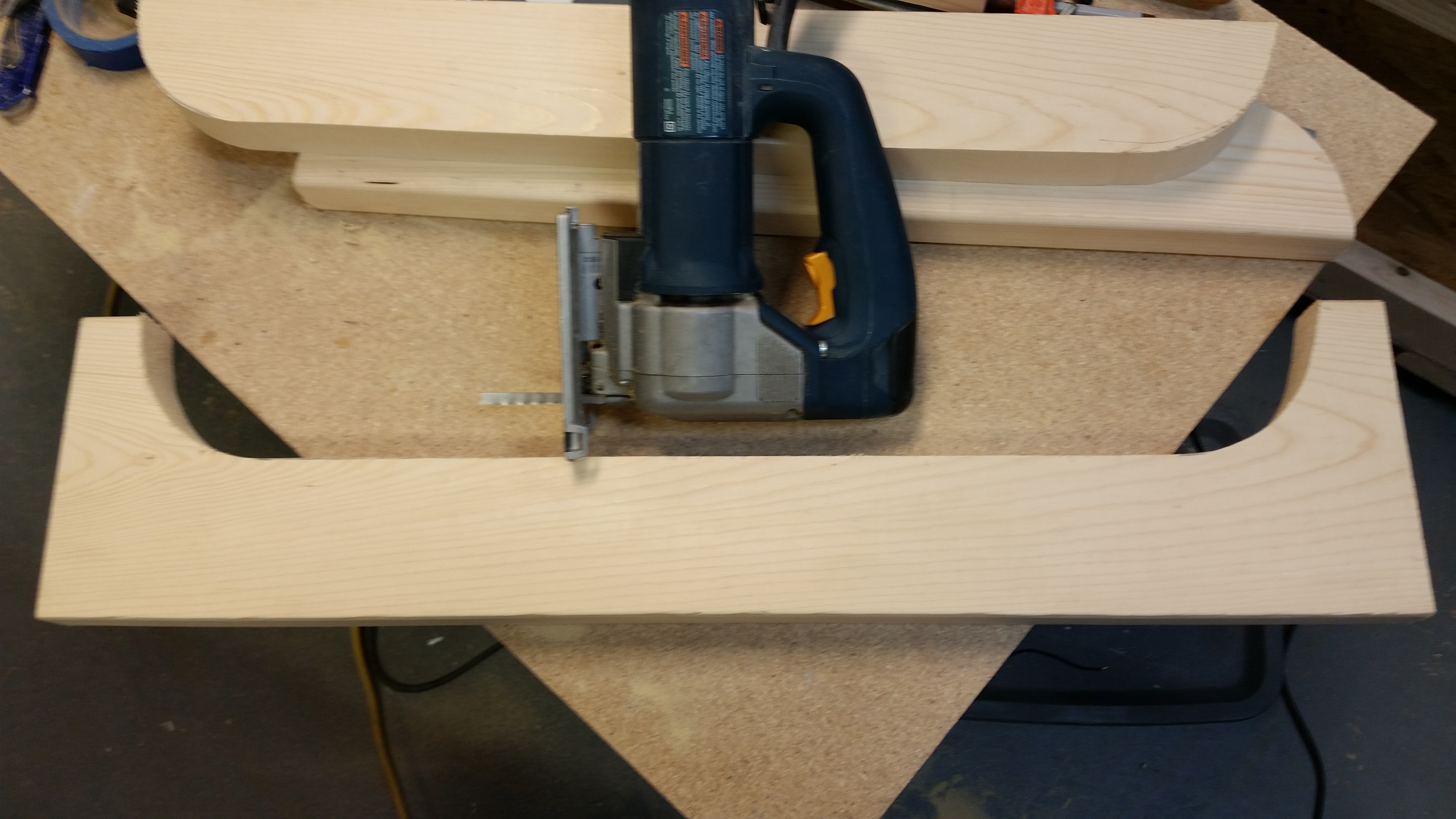
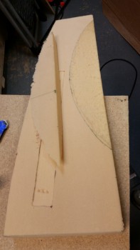
As I mentioned at the start of this post, with the location of my pedal bases set & confirmed, I could now dish out the inboard side of each floor pan.  I started by removing about 90% of the material with a coping saw.

Dishing out inboard side floor pan

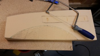
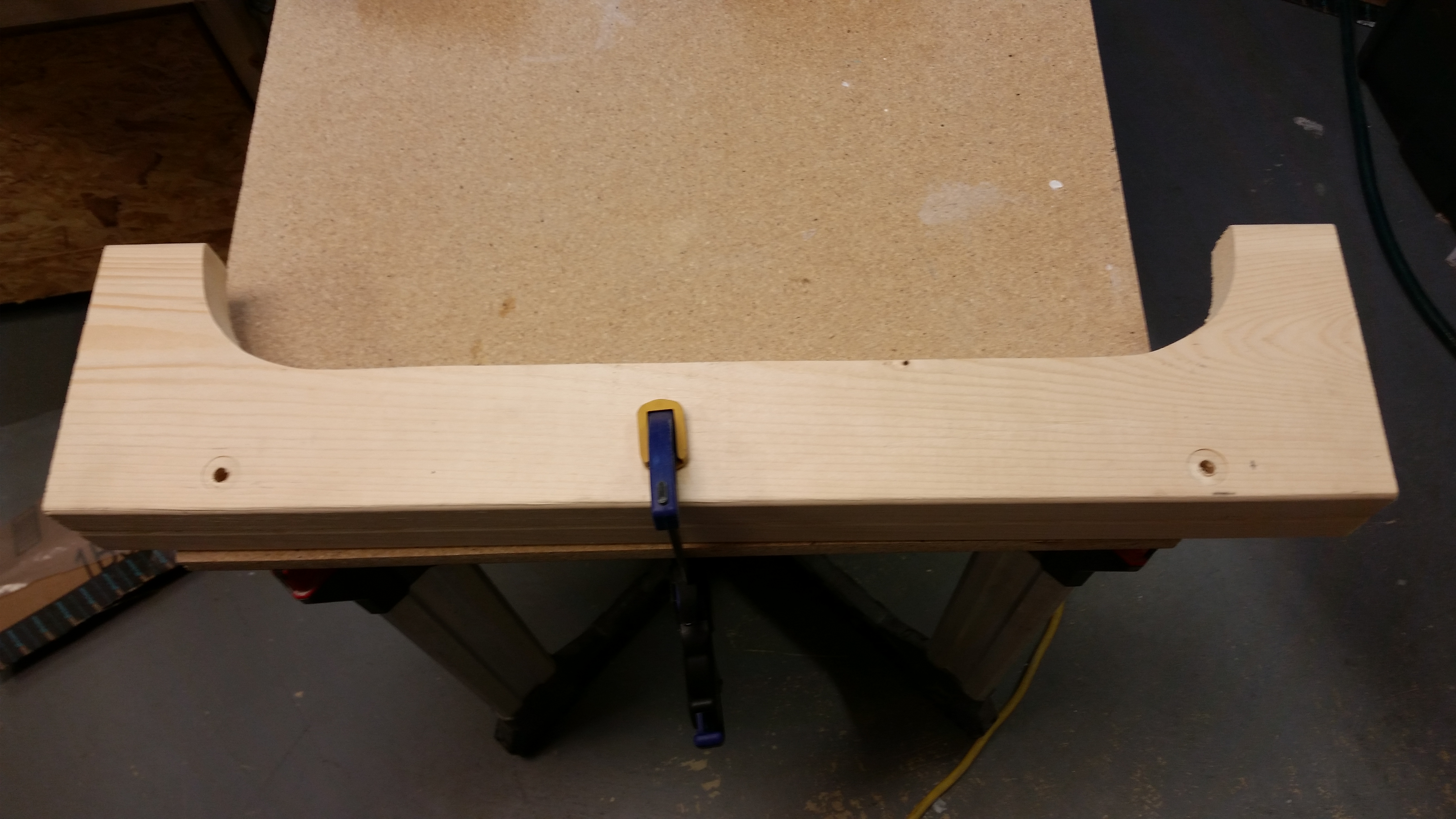
I then used my half-moon Perma-Grit tool to remove the rest of the material and sand the dished out area to its final shape.

After the inboard edges were dished out, I then expanded the depressions in the foam for the K1000-3 nutplates just a tad to provide the proper clearance when the rudder pedal base plates are micro’d into place in the floor pans.

Dishing out inboard side floor pan

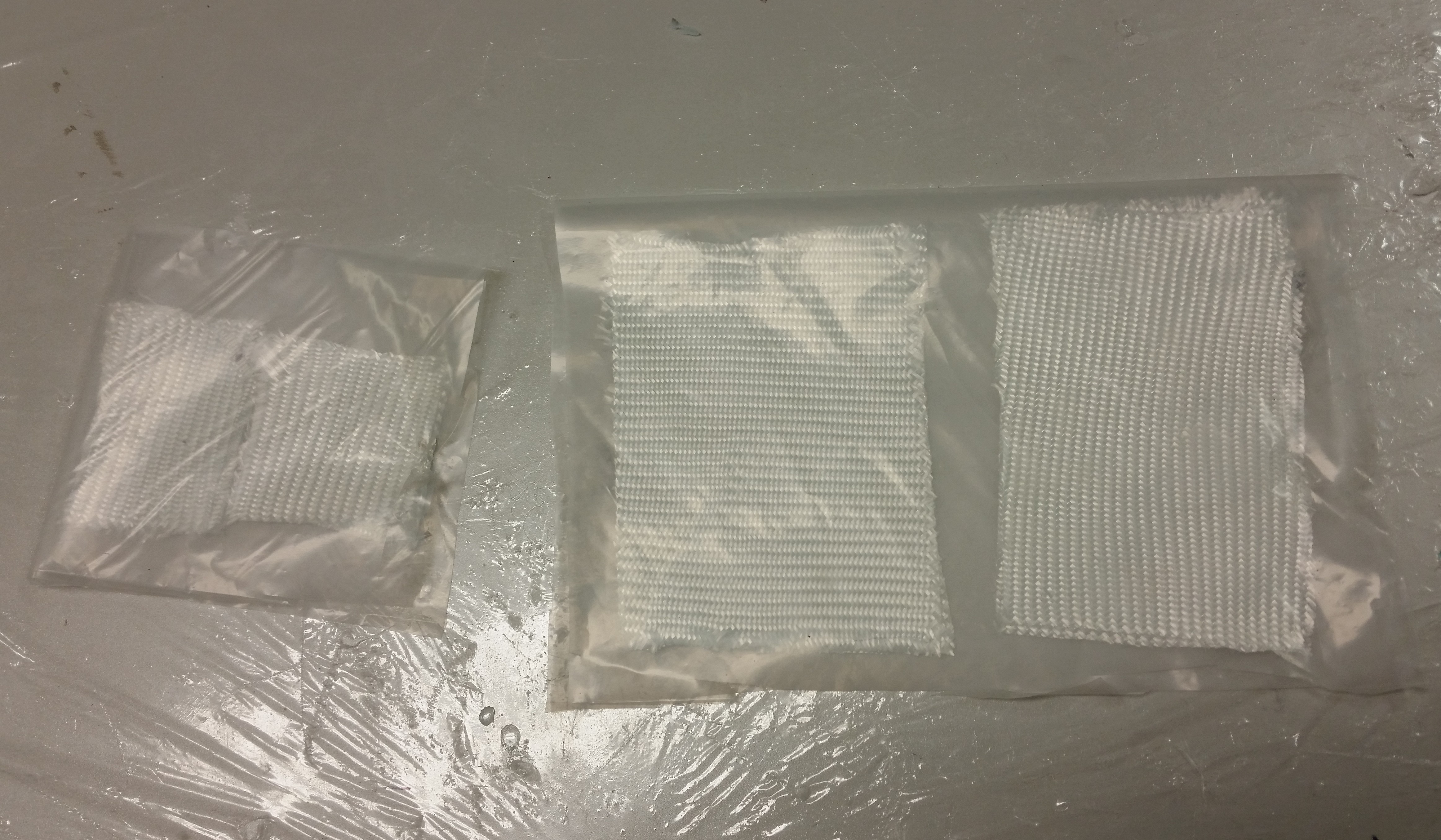
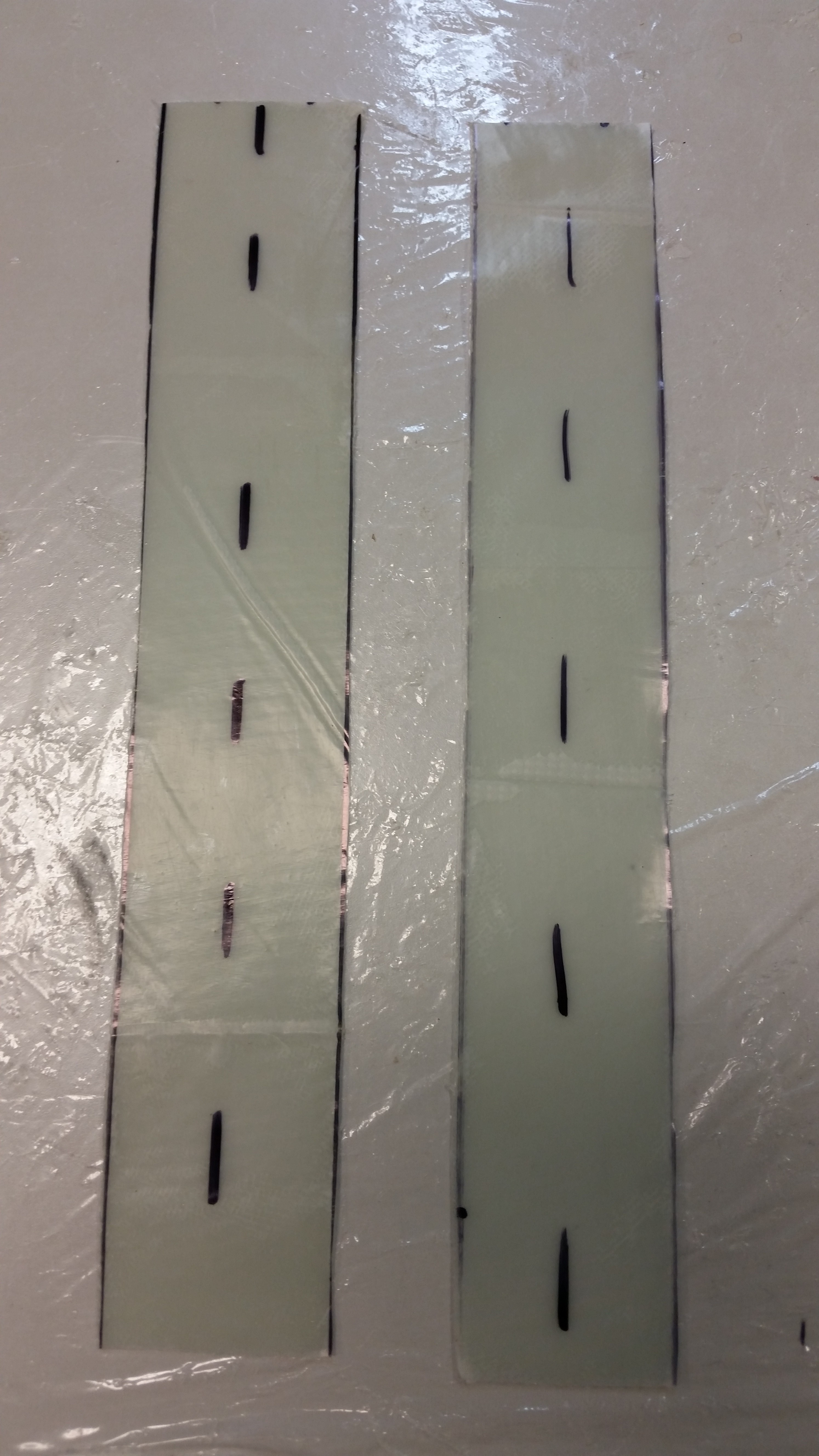
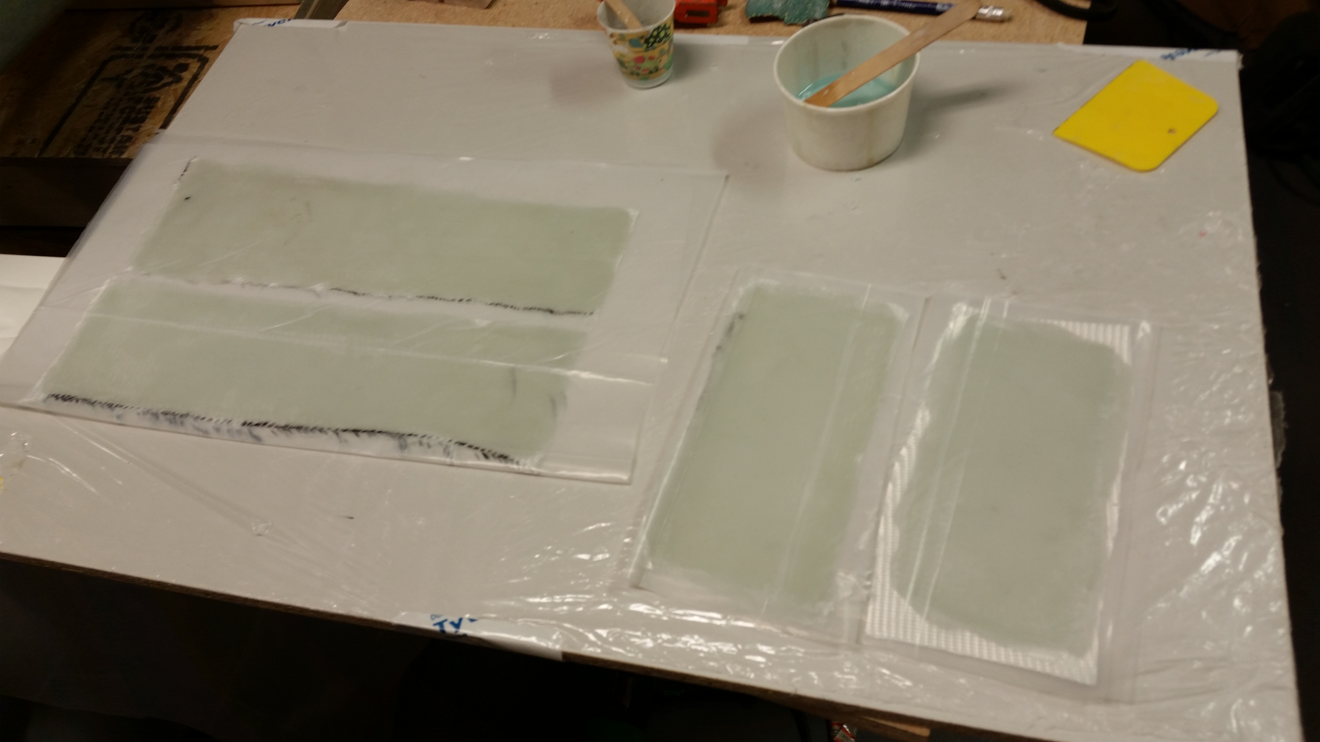
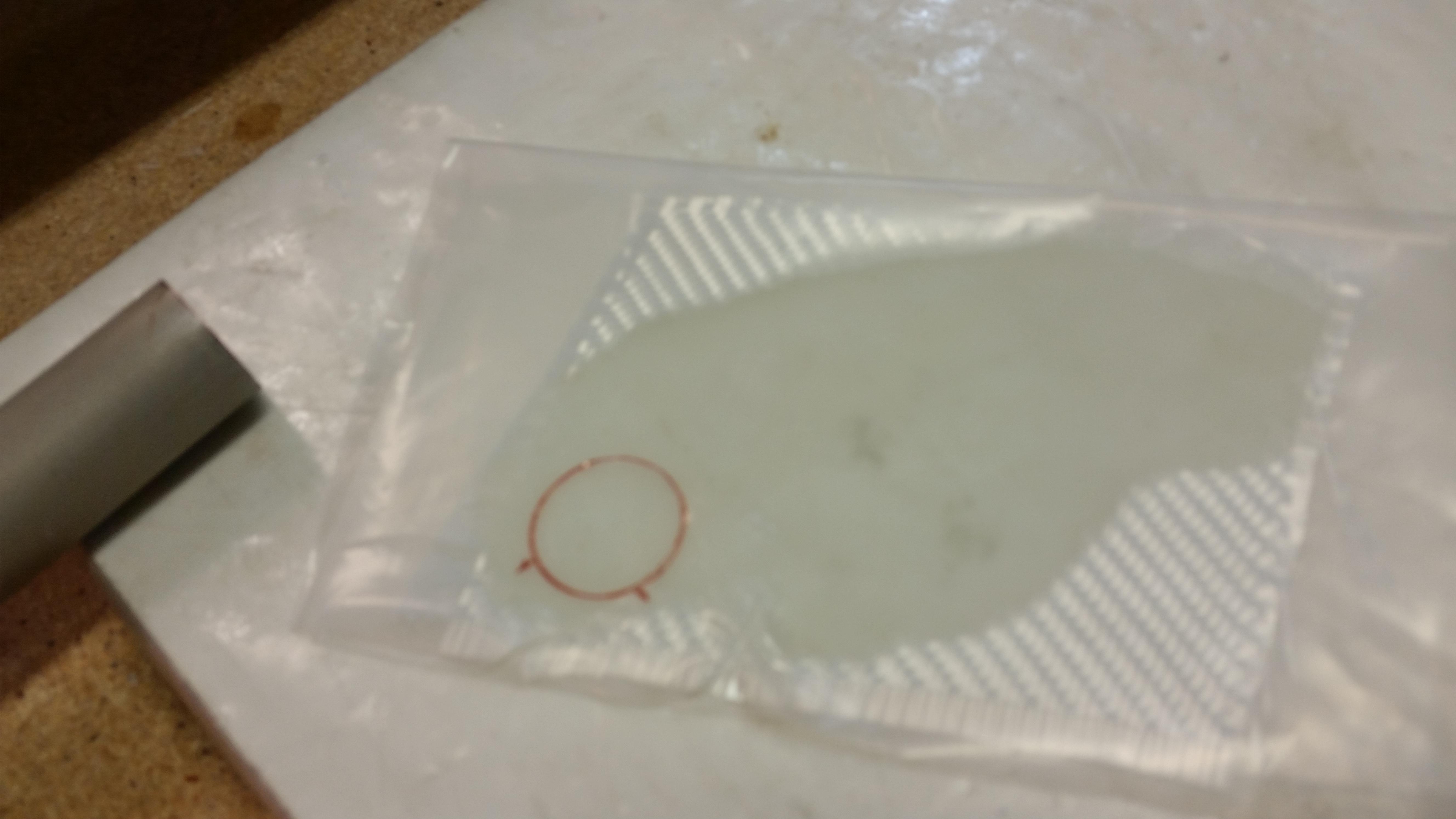
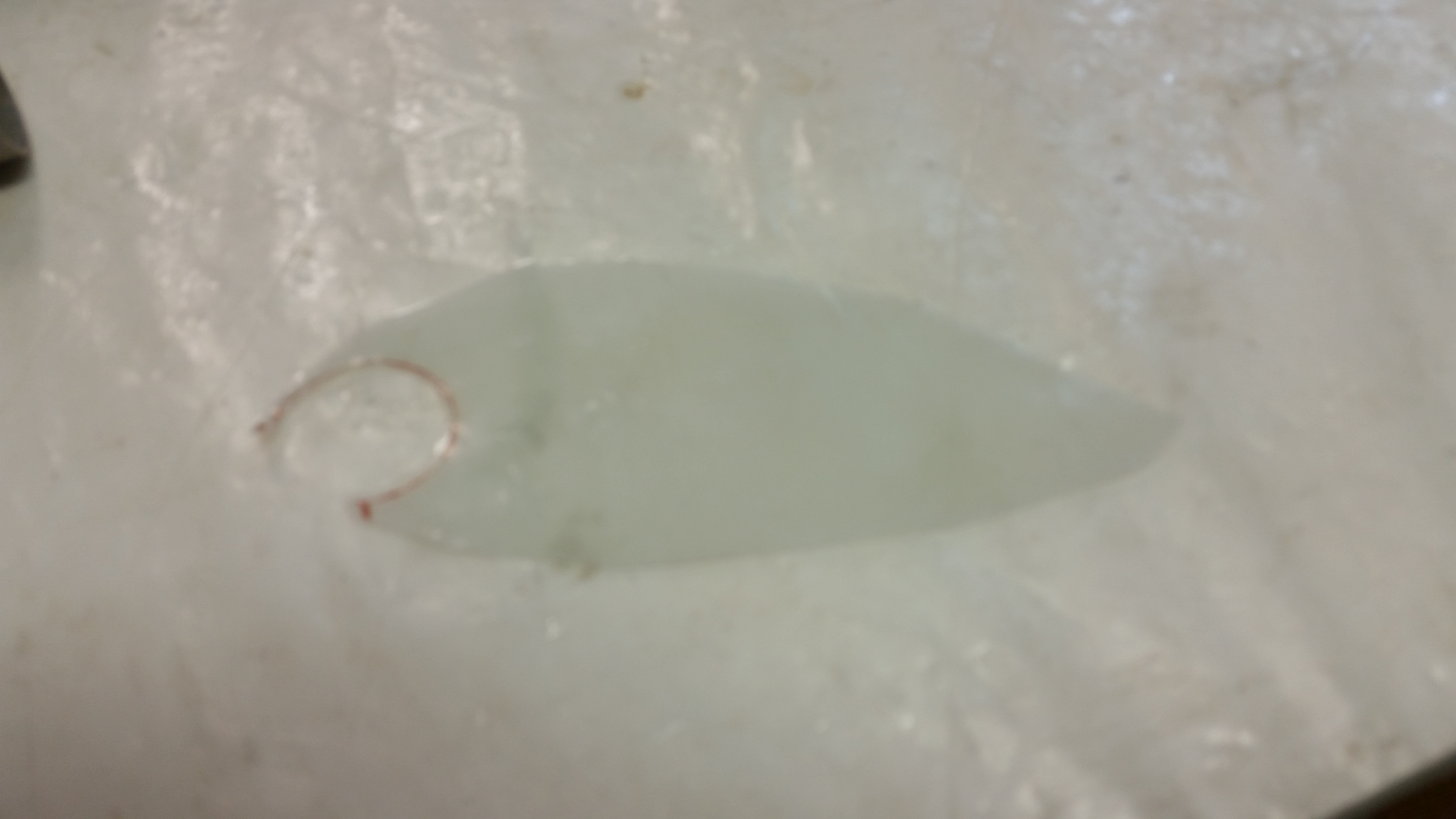
Since it was raining outside, I had to reorganize the shop a bit & play musical chairs with my motorcycle to get access to my glass cutting table.  Once table access was “granted,” I then cut out 2 pieces of BID for each floor pan and 3 pieces of BID for each sidewall piece.

While cutting the BID, I used up the final bit of glass on the roll mounted in my cutting table. I loaded up another roll, and have to say this time it felt really good because I knew that this would be the last roll of BID that I will use for this project!

Last BID roll

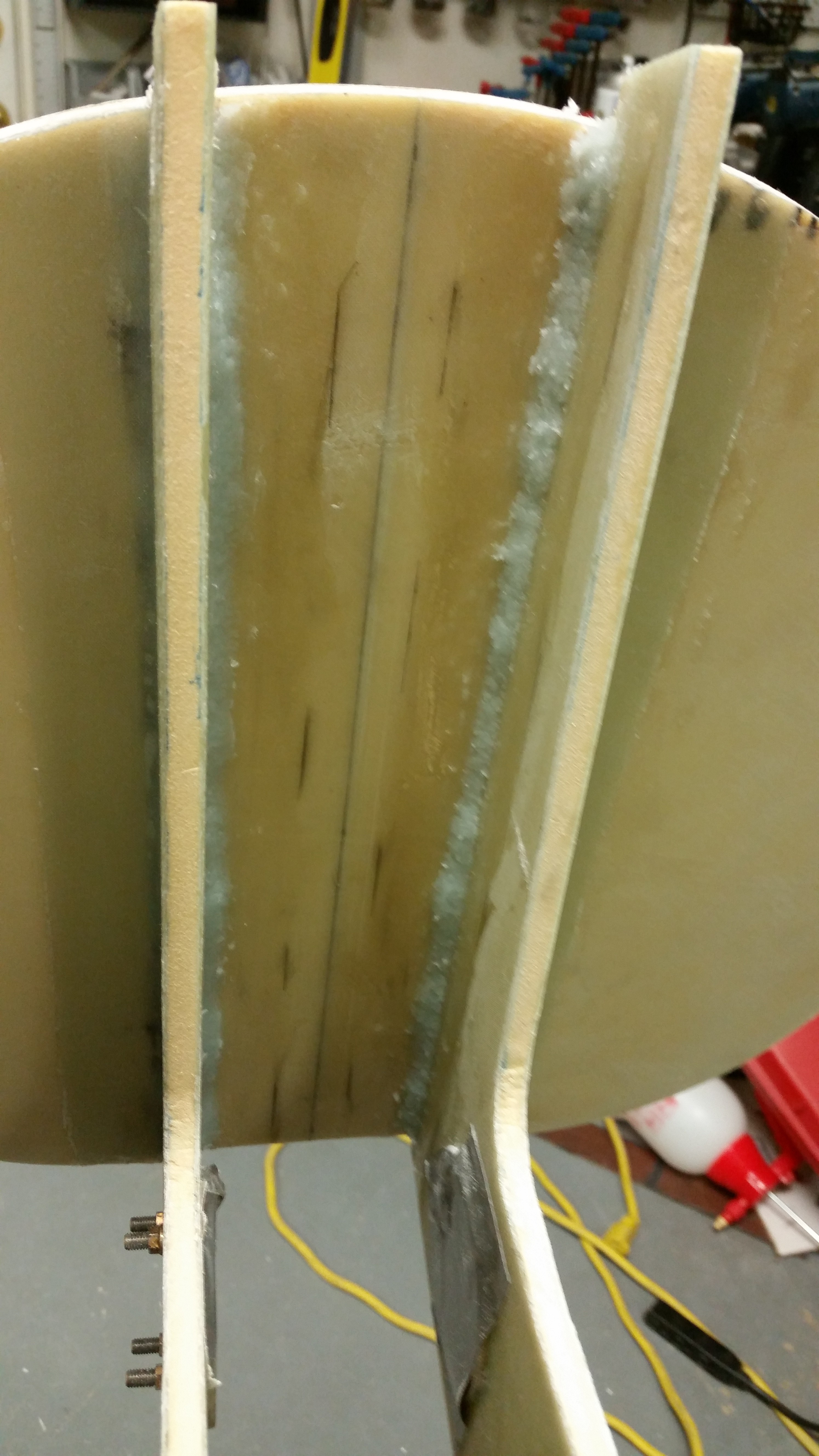
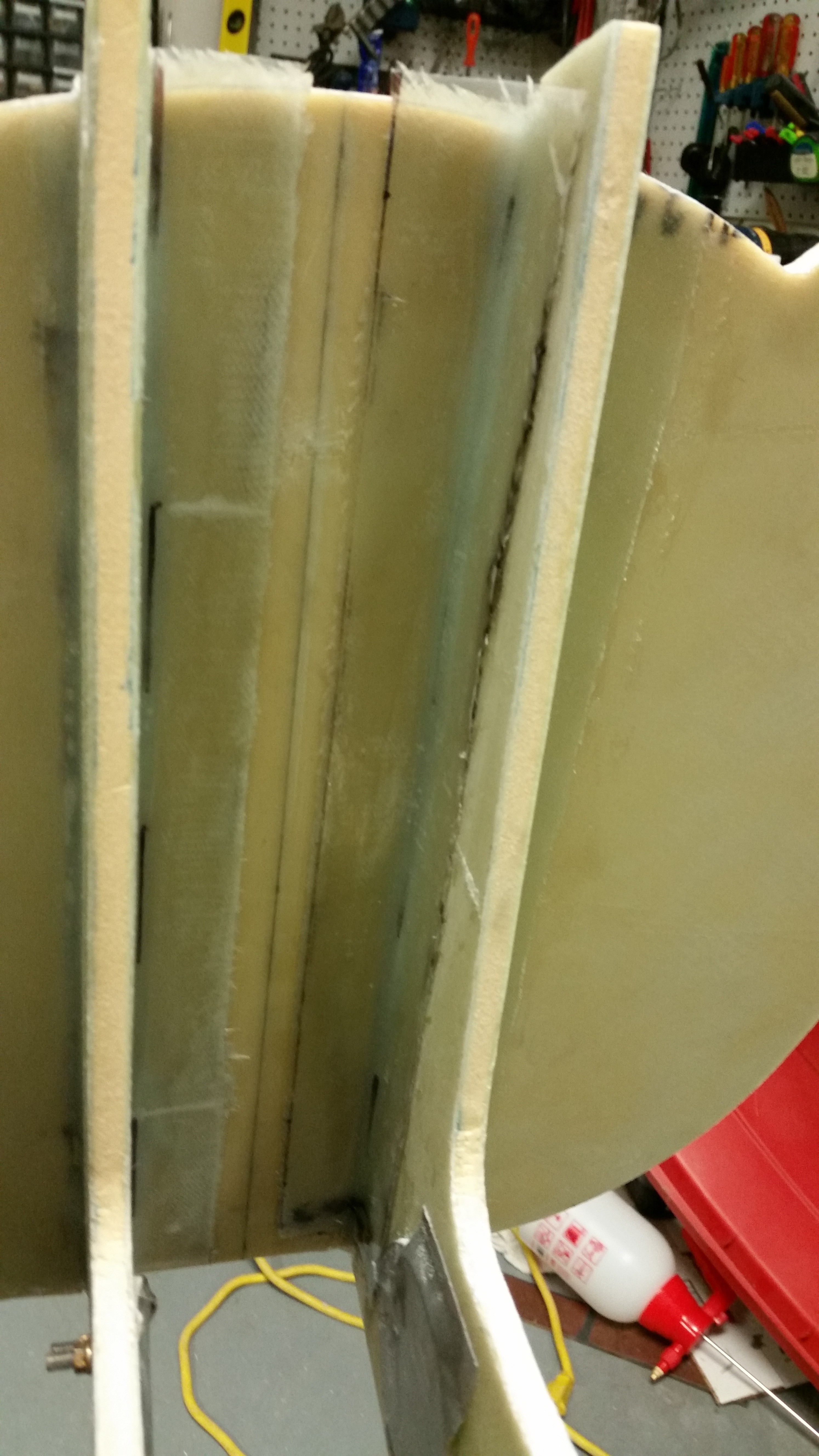
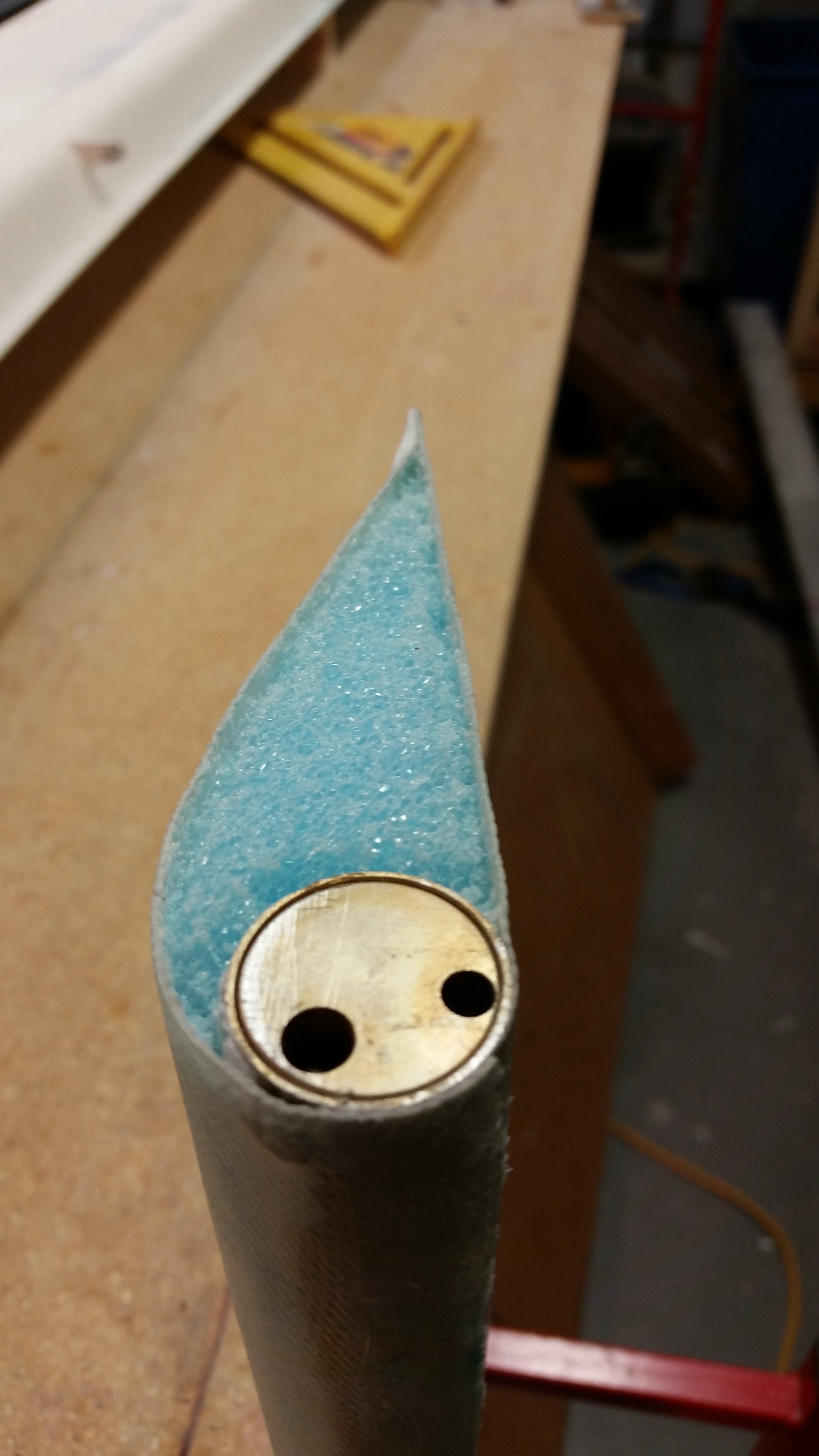
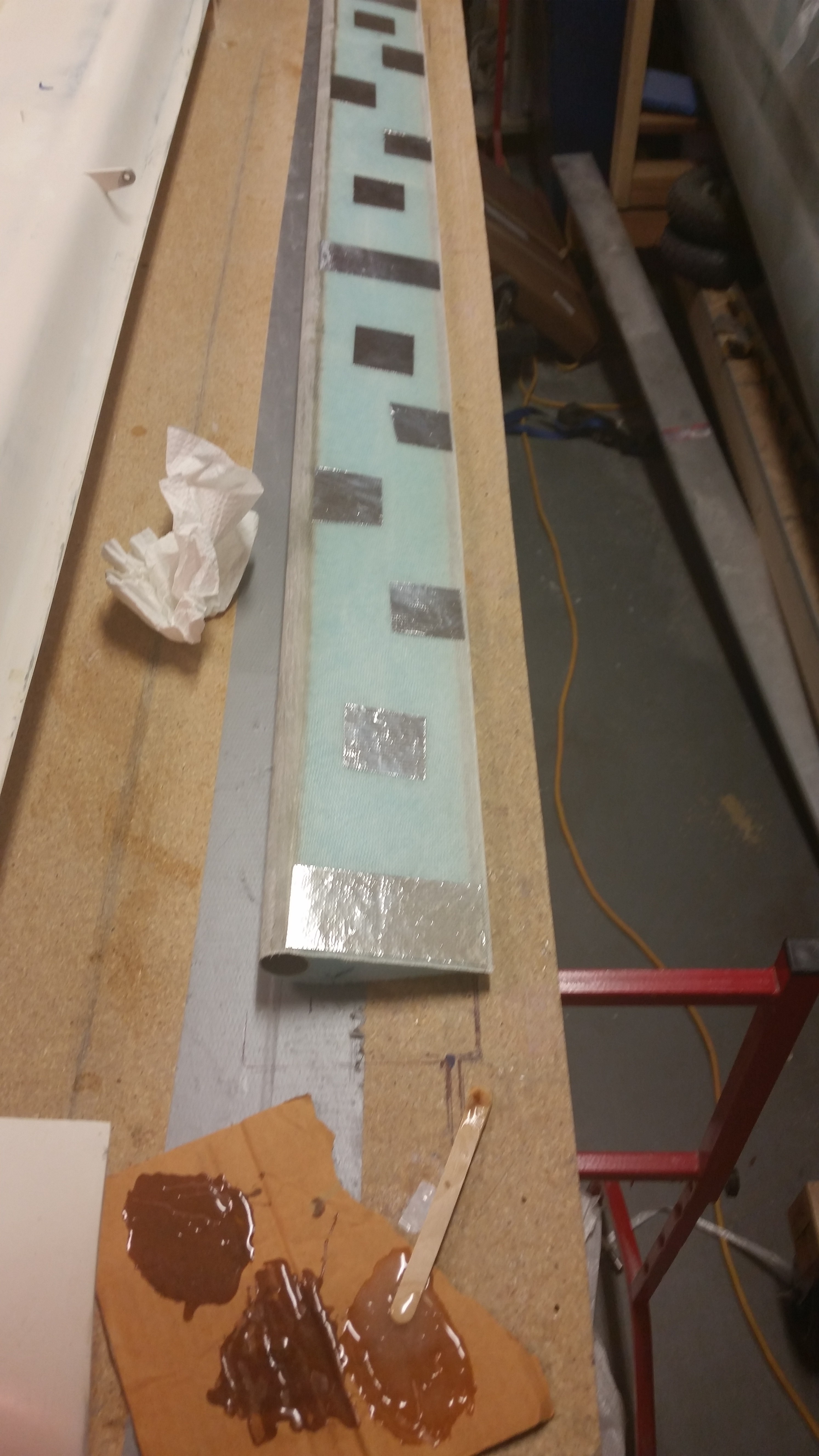
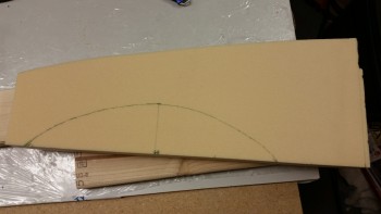
Now, the plans call for 2 pieces of BID for each sidewall piece, so why am I adding a third piece?  Because I’m breaking the rules.  The plans for the Davenport nose say specifically NOT to dish out the side walls, but having nearly 2″ thick Divinycell side walls for an 11″ nose extension is a bit of overkill in my opinion.  Since the foam is so thick, when matching up the sidewall with the opening in F22, the plans do call out for dishing out the side wall to ensure a smooth transition with inboard edge of the F22 sidewall.

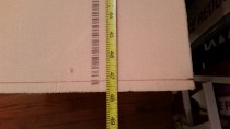
Thus, my plan is to leave the bottom of the sidewall the normal width for this install, but in the area above where the sidewall gets dished out, I narrowed the sidewall foam to 1.1″.  I figure if the Ronenburg extended nose and others call for 0.8″ thick sidewalls using blue wing foam, than 1.1″ thick Divinycell on the top half of the sidewall with an extra ply of BID will be plenty strong.

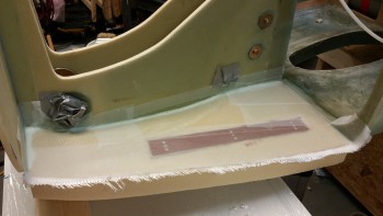
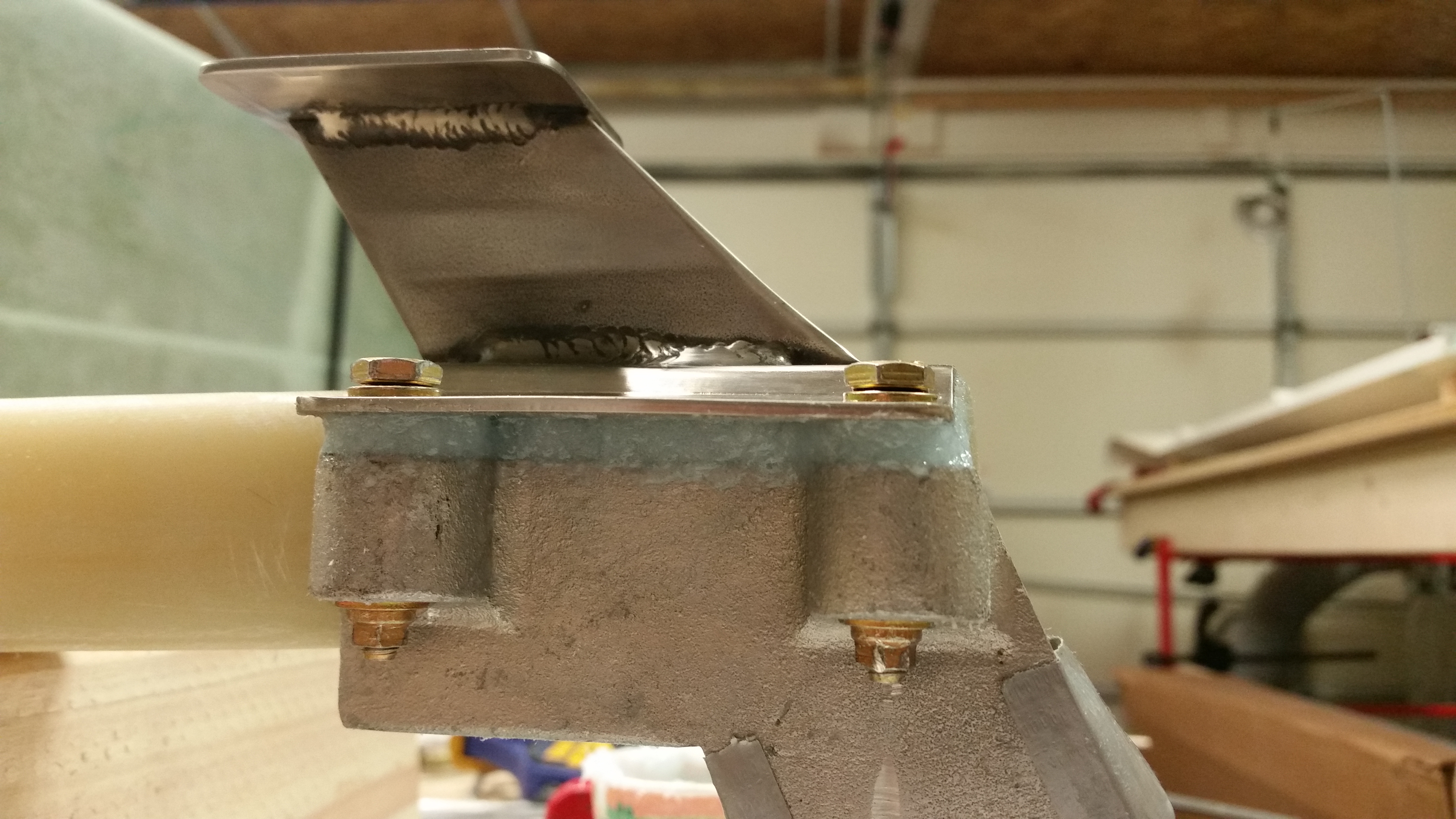
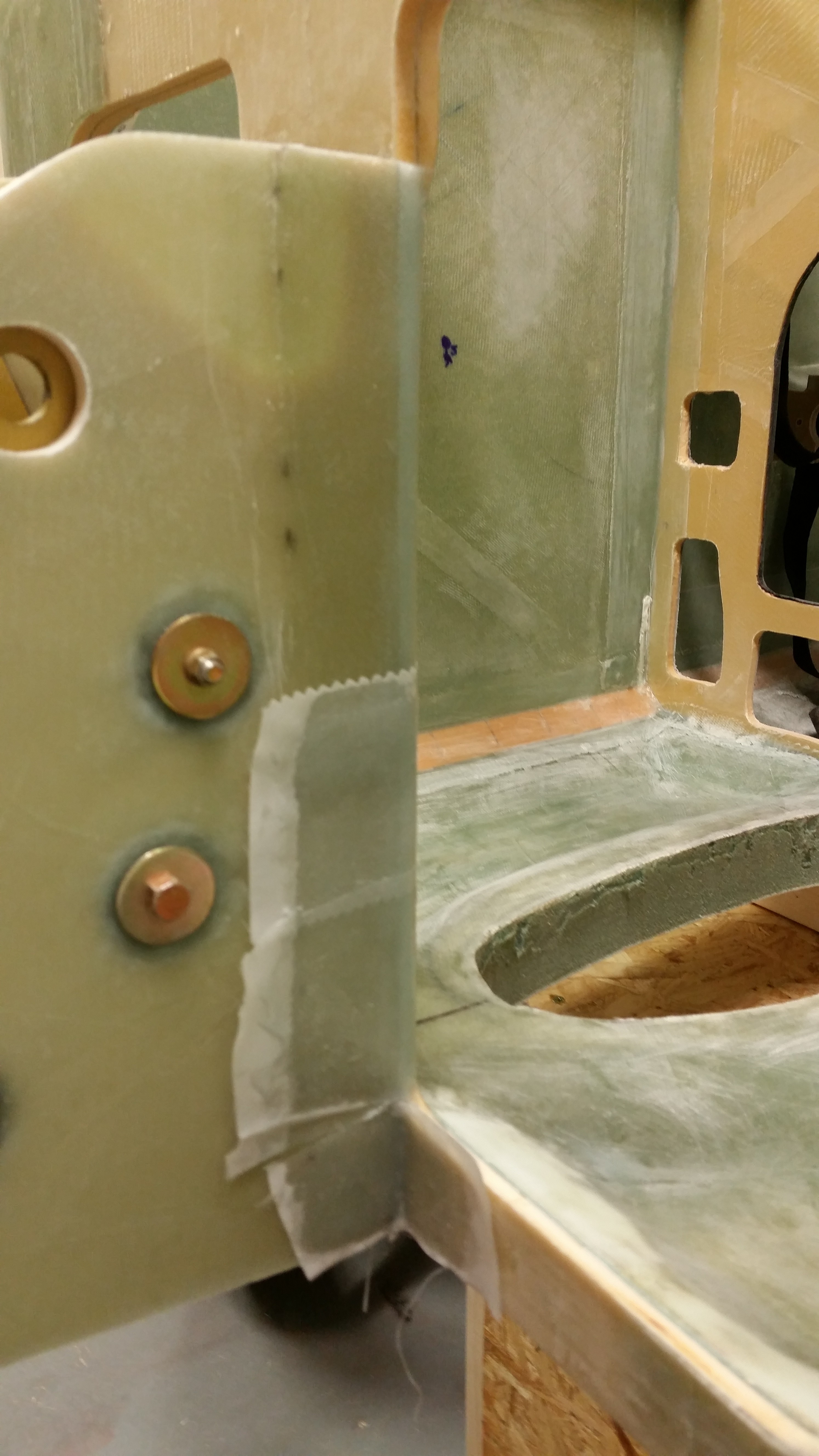
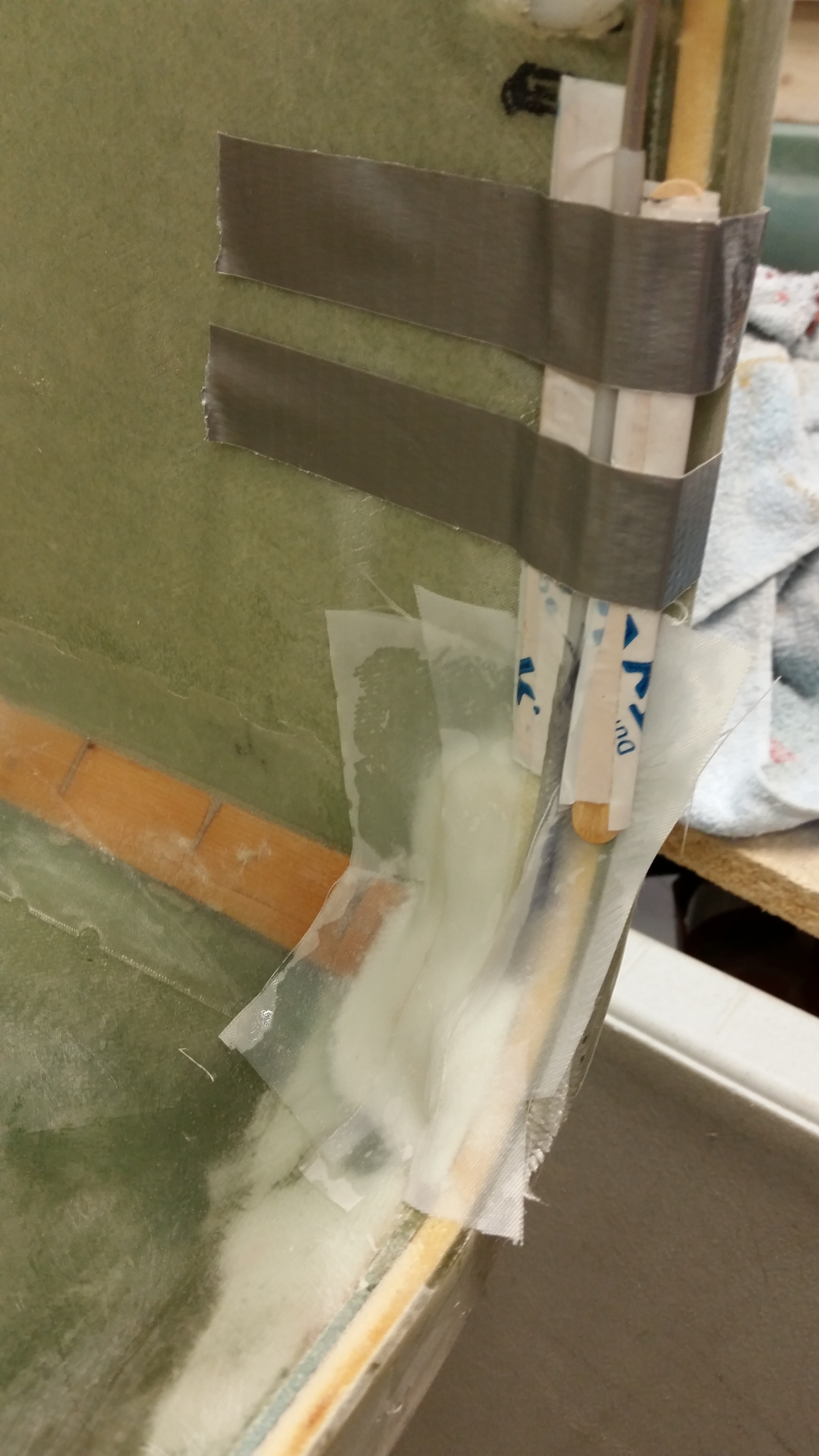
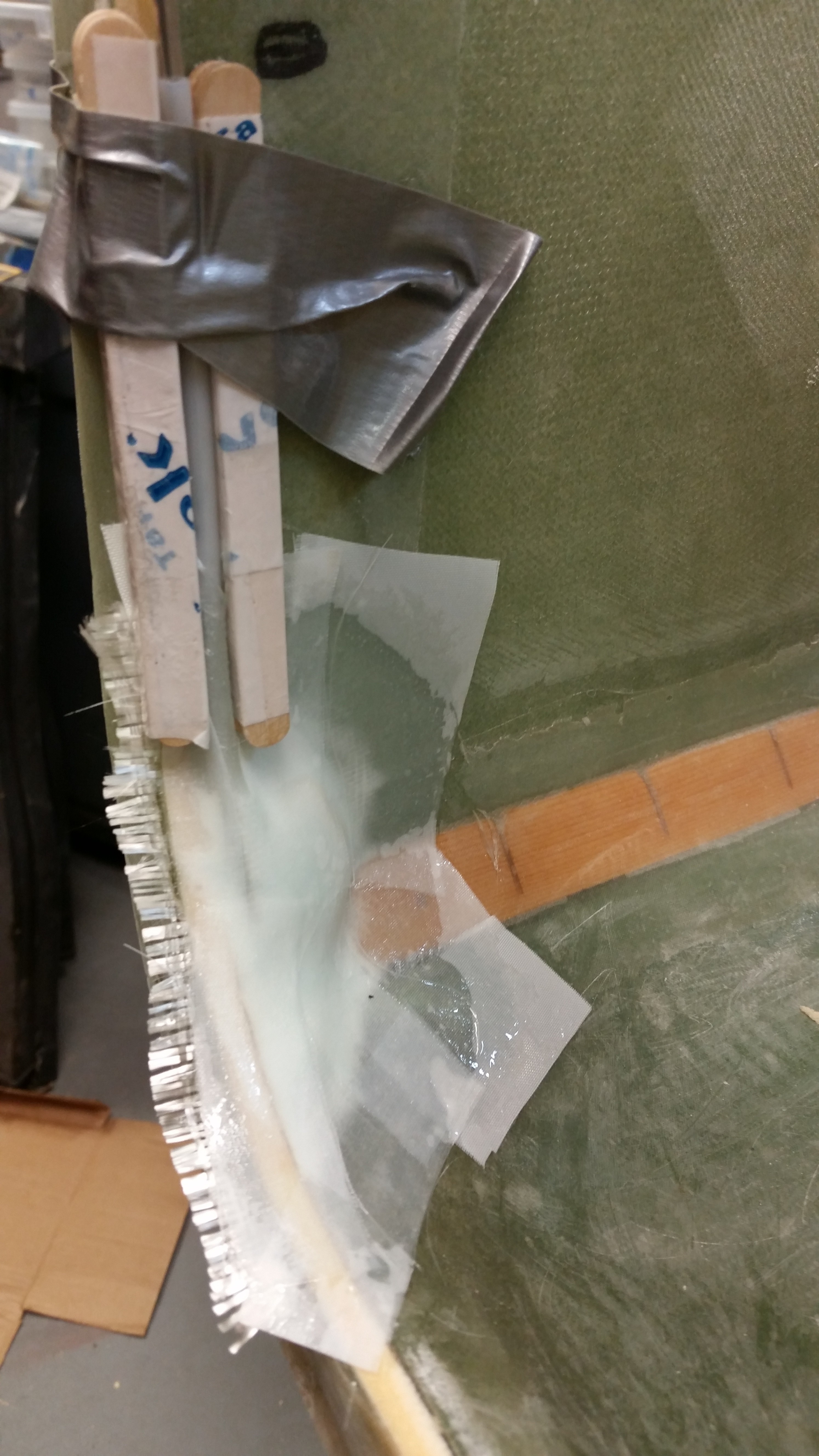
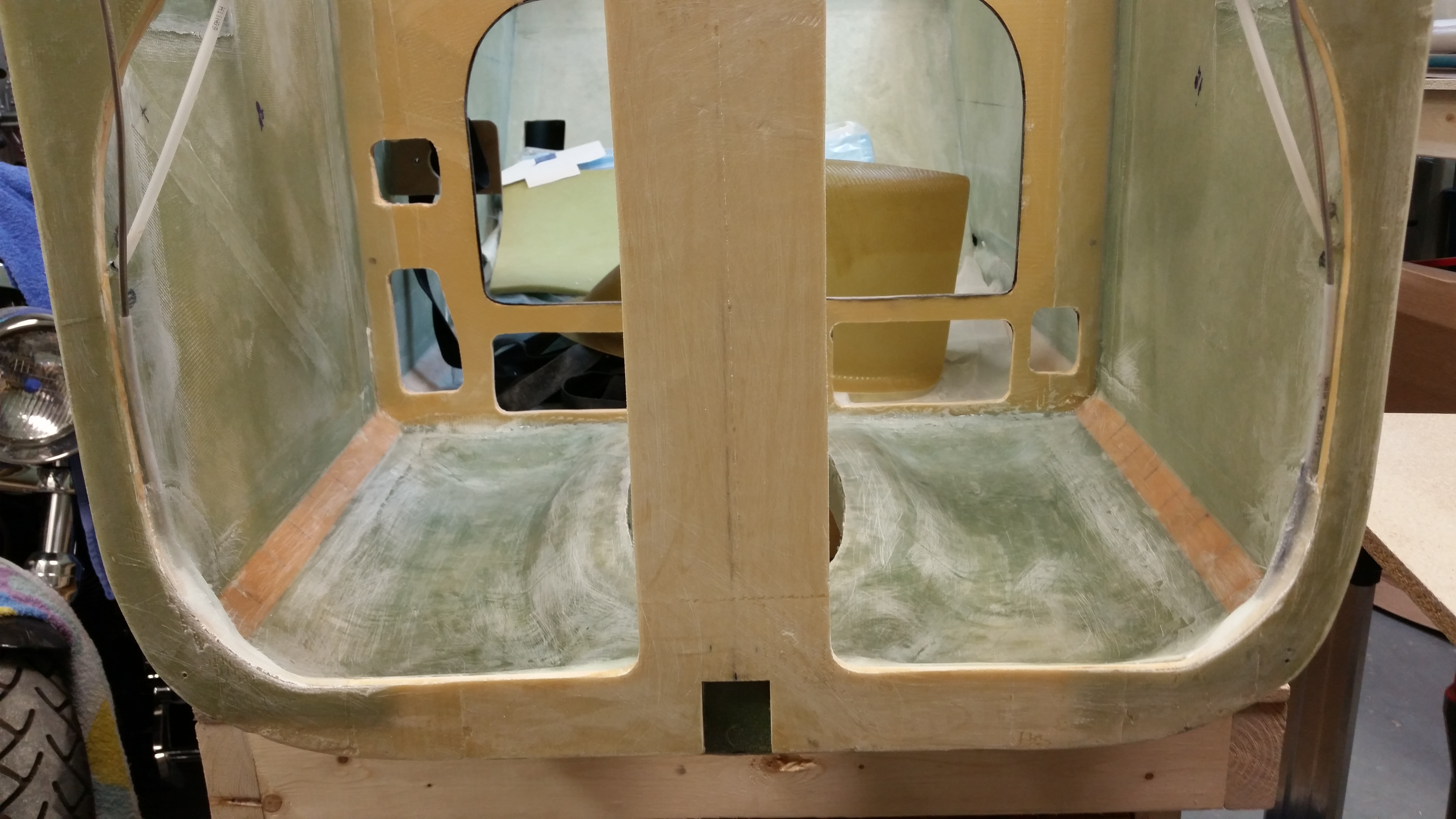
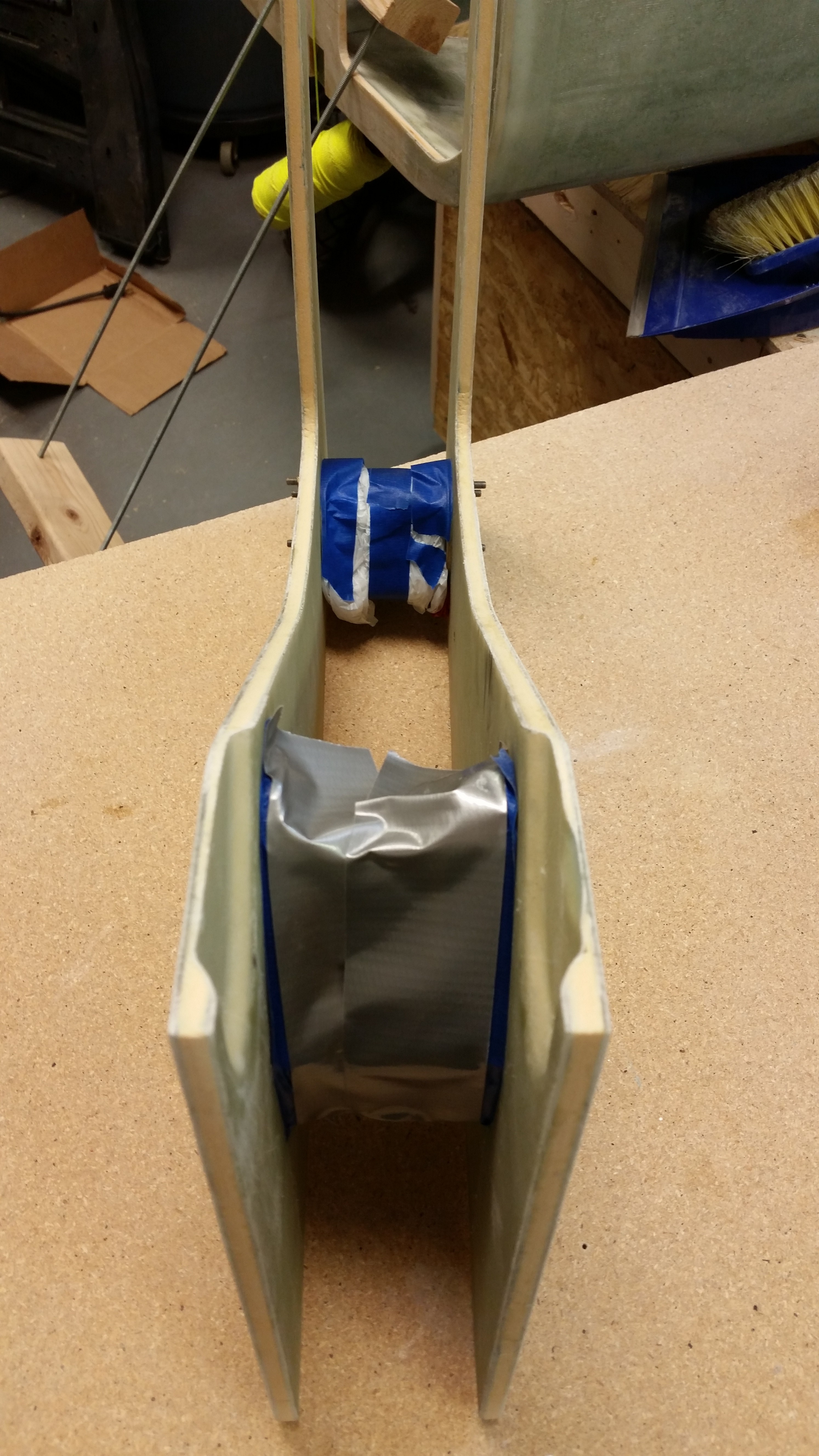
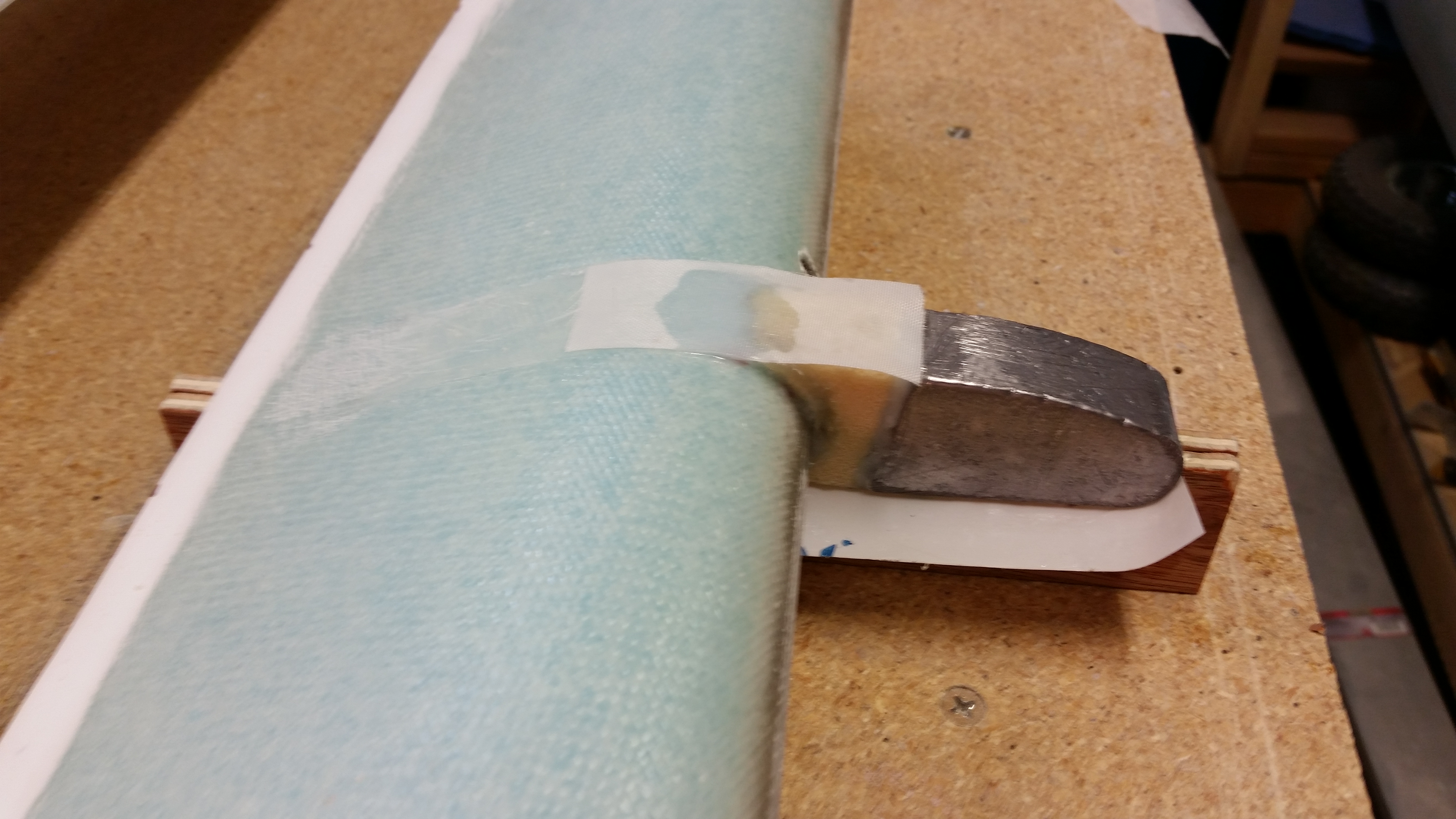
With everything prepped on the floor pans, after one final fitting check, I whipped up some micro and slathered it on the surface areas that would mate with the existing nose components.  Since the 10° called out for in the plans is just a tad bit too severe, I needed to fill a about 0.050″ gap in-between the floor pan and the F22 bottom front, so I mixed in some flox to create some flocro to apply to the back edge of the floor pan.  That explains the slightly different consistency & color you see between the edge micro and the back flocro that is visible in the pic below.

Microing edge of floor pan for install

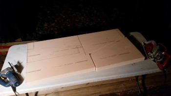
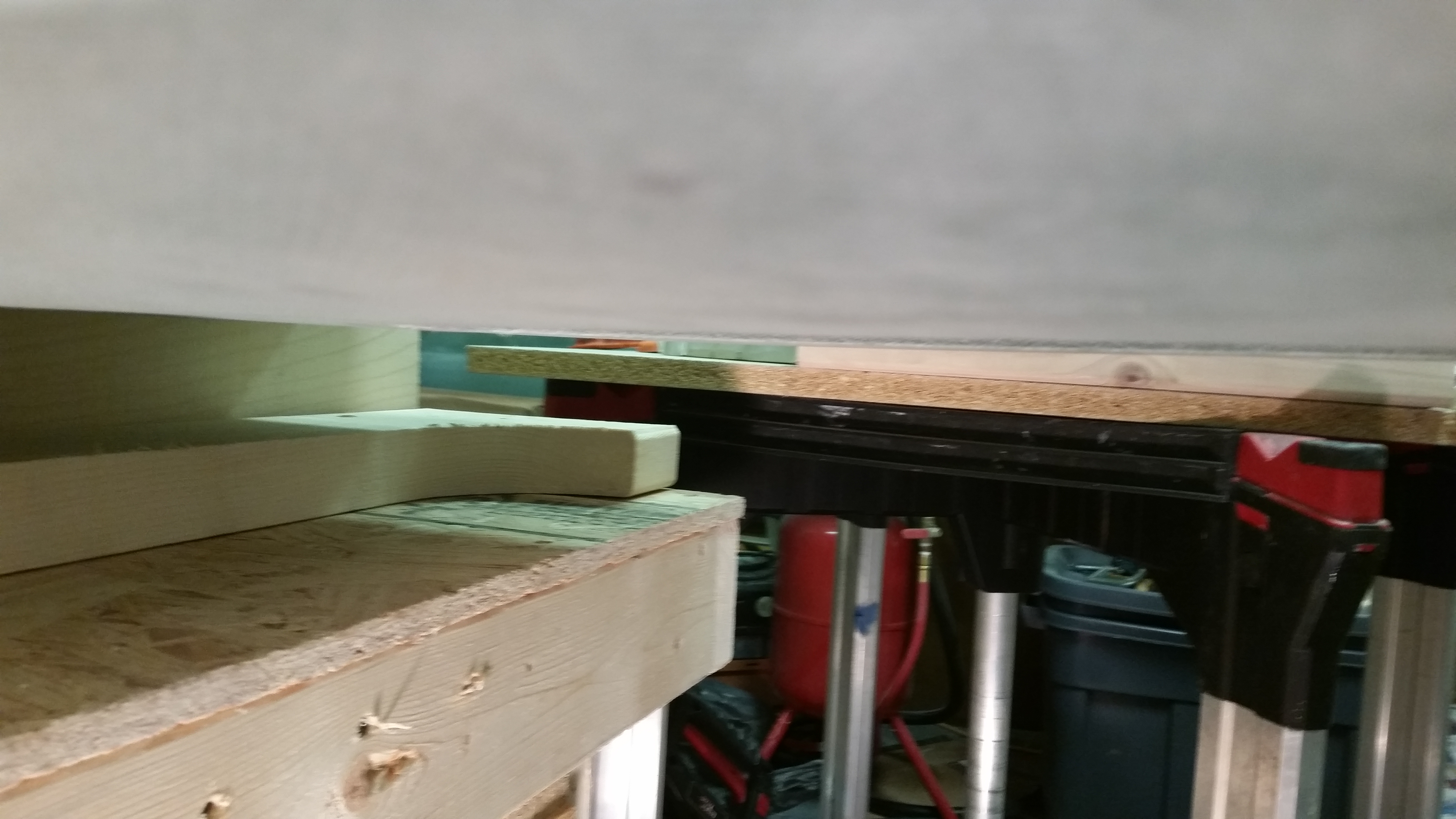
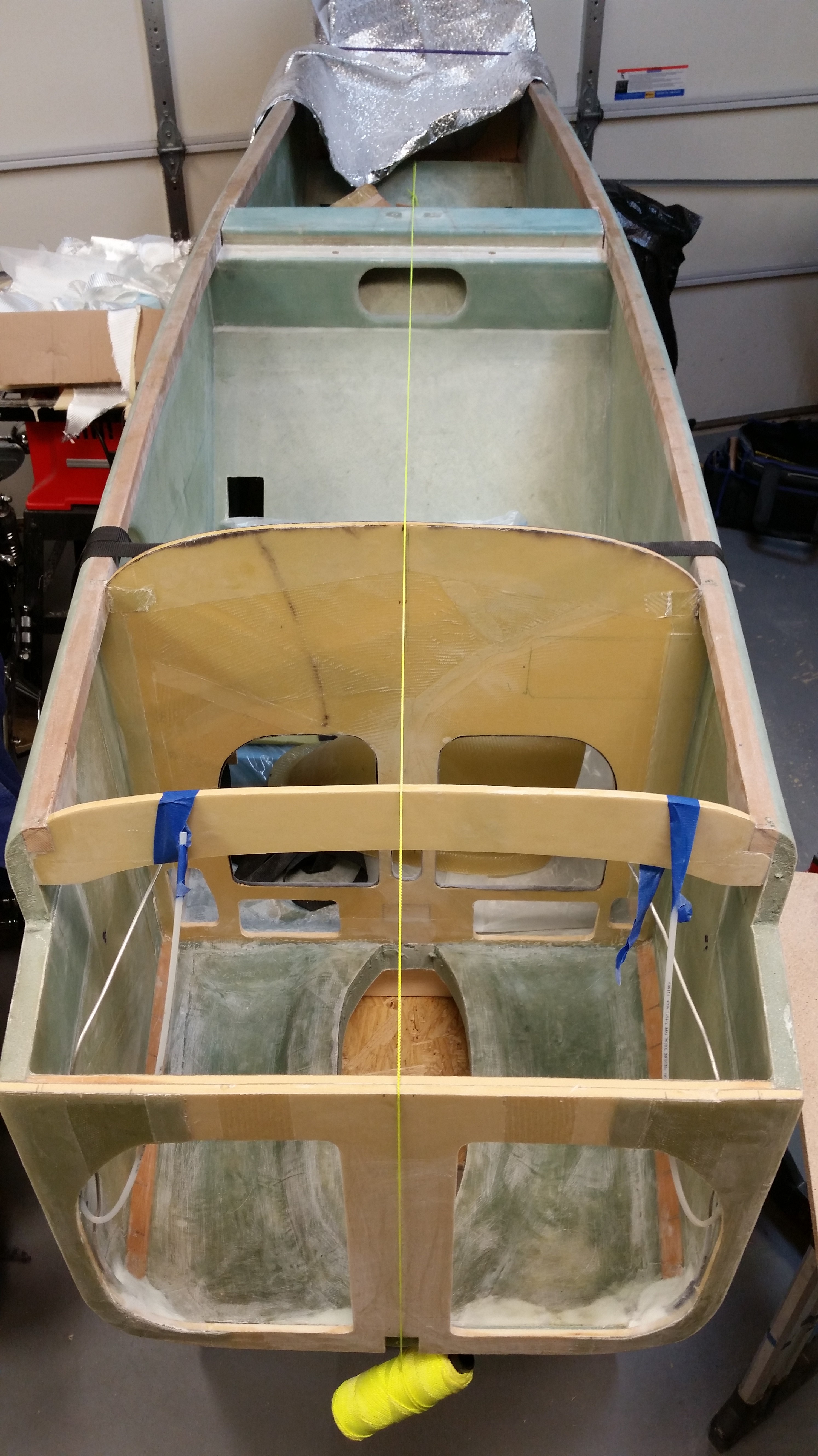
I mounted the right floor pan first & then clamped it into place.

Right floor pan installed

I then micro’d up the edges of the left floor pan and installed it.  When I pulled the clamp off of the right floor pan to install the left one, there was very slight gap that was created between the NG30 and the floor pan.  Although I had planned on glassing the floor pans this evening, it got me to think that I wanted the seams as tight as possible, so I simply re-clamped both floor pans together and decided to let it all cure overnight.

Left floor pan installed

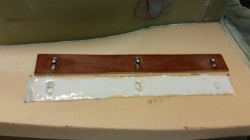
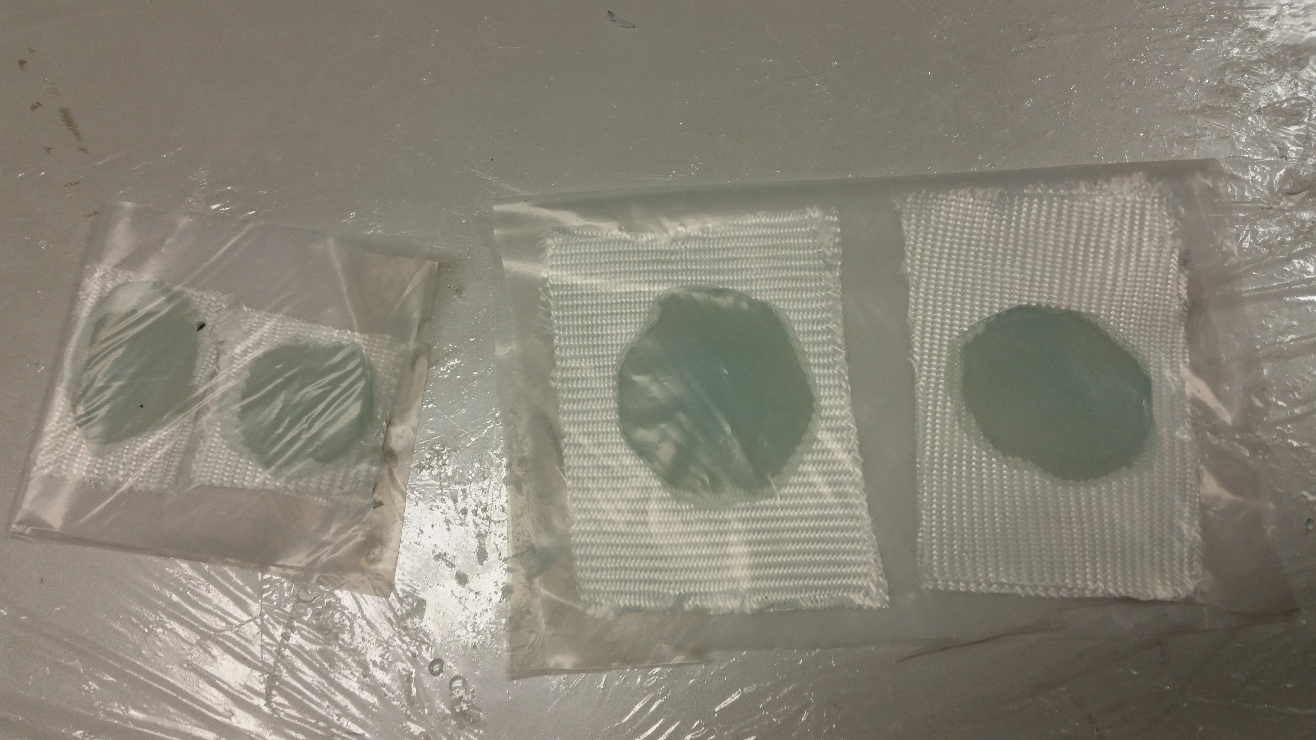
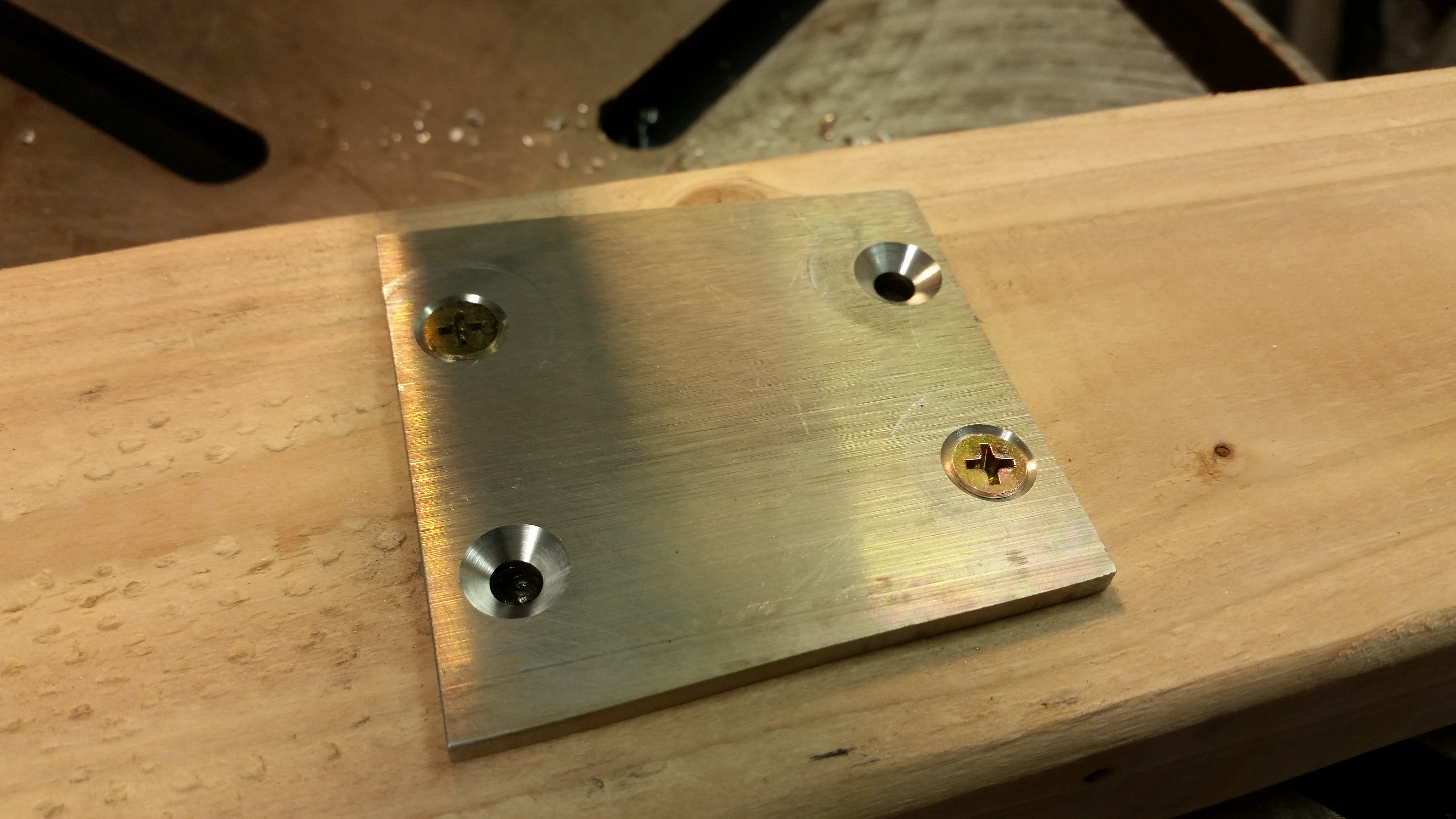
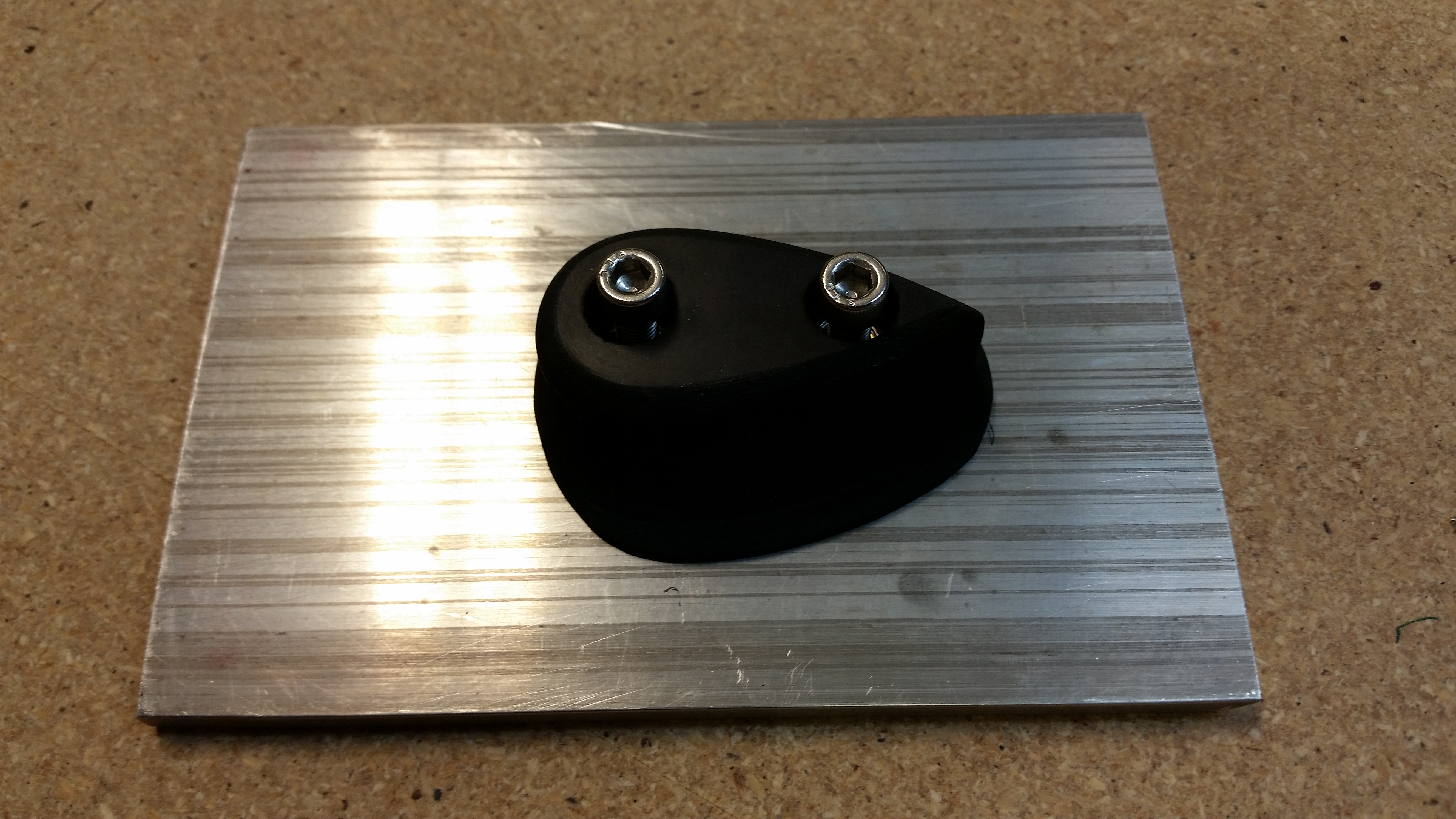
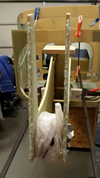
I then got to work sanding the phenolic rudder pedal bases with 100 grit sandpaper.  You can see below that the left base is sanded while the right one isn’t.

Sanding rudder pedal base for install

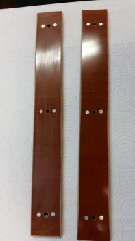
I then filled the K1000-3 nutplate bolt holes with saran wrap and did a final test fit for each rudder pedal base into the floor pan foam.  I’ll micro in the pedal base plates just prior to glassing the floor pans.

Rudder pedal base prepped for install

Rudder pedal base prepped for install

Tomorrow will be a rather busy day work-wise, etc. but I do intend on getting the floor pans glassed as a minimum.


Chapter 13 – Looking down my nose…

I started out today working on permanently mounting the NG15 (technically the MKNG15B) casting to the end of the nose gear strut.

Prepping NG15 for flox install

I attached the stainless steel foot rest after slathering up all the surfaces with flox.  Here’s the end result.

NG15 floxed & bolted in place

I find that both the original plans and a lot of vendors that sell parts for the Long-EZ often call out for bolts that are simply too long.  The same holds true for mounting the NG15 in that CP#51 recommends that builders upgrade to AN3-14A bolts, which were way too long.  So I ended up using AN3-12A bolts like a number of other builders I know.

NG15 floxed & bolted in place

As the flox cured I worked on converting the P2 connector on the AEX from a 9-pin Molex to a 9-pin AMP CPC connector.  Below are a couple of shots mid-mod.

Converting AEX to AMP CPC

Converting AEX to AMP CPC

I then wrapped the wires with self-amalgamating (“centerline”) tape.

Converting AEX to AMP CPC

And finalized the conversion by mounting the cable clamp.

AEX converted to AMP CPC connector

Now, I’m going to quickly get on my soap box.  I’m incredibly grateful as an airplane builder to have a company like Aircraft Spruce to buy the stuff required to build an airplane that would be close to impossible to find anywhere else.

With that being said, as much money as I’ve spent there over the past 5 years, you’d think that when buying an almost $100 piece of foam that is supposed to be 24×48 inches, that I’d actually get what I paid for… not one that is short and malformed on one end and cracked at the other corner on the other end.

ACS foam issues

The good news is I still had enough to cut out the nose panels, although the foam that ACS delivered is unsat & not cool.

Now, back to the build.  Since I only bought one piece of this foam, I needed to squeeze every square inch out of it that I could.  I spent a bit of time figuring out a cut sheet to optimize the foam usage.  I came up with the configuration below and marked up the foam.

Note feet pans & side walls

Once I verified the dimension were correct I marked the actual cut lines that I would use for the initial cutout of the panel with my Skil saw.

Foam cut marks

I then set up a cutting table out back and cut the panels out.

First panel cut

And here are the results.

Nose side walls & floor pans

Tomorrow I plan to shape the panels to their final dimensions, work on the rudder pedal placement and install the floor pans.


Chapter 13 & 22 – The Napster Riseth!

Since I had to remove the NG6B and gear strut assembly to glass the inboard F1-3 bulkhead (“Napster”), I started off today by greasing up the NG6B bearings.

NG6B bearings

Here’s an action shot of me greasing the bearings!

Greasing NG6B Bearings

I then started on the gear strut channel that runs from F22 aft to the wheel well.  The first task was to mark the cut lines.

Marking gear strut channel

I then cut the lines with the Fein saw.

Cutting gear strut channel

And cleared out the dead glass, foam, etc.

"De-foaming" gear strut channel

Here’s a shot of the nose wheel spacing.

Nose wheel clearanceOk, some of my fellow builders have discussed the issue of the stock nose wheel sticking out down below the bottom of the fuselage, normally around 1/4″ to 1/2″.  Fortunately, I don’t have this issue on my bird, and it’s all really because of a serendipitous reason.

When the foam called out per CP 34 back in 1982 changed from the old PVC to the now standard Divinycell, the foam for the fuselage bottom changed from 1.6″ to 1.75″ thick.  Thus, when I built the F22 to the plans height dimensions the fuselage bottom ended up almost 0.2″ lower than the bottom edge of the F22.  I don’t remember all my reasons for doing so right now, but I didn’t sand the bottom fuselage surface to blend into the bottom of F22 (you can see this in a couple pics above).  One reason I left the bottom fuselage foam at 1.75″ was so that the entire nose structure would be a bit lower.

Nose wheel tucked away!

Now, let’s fast forward to a few days ago when I mounted the NG30s to the front of F22.  To keep the bottom of the fuselage even, I dropped the NG30s even with the fuselage foam.  Obviously when I did this it dropped the Water Line (W.L.) of the nose gear pivot down by about 0.2″.  This time around, I was hoping that the lower fuselage/nose gear box would result in an angle that would avoid any further messing around with the gear strut, etc. to fix a less than shy nose wheel.

Well, it did.  When I cut the nose gear strut channel, mocked up the nose gear, and checked the spacing of the wheel in the wheel well I was pleasantly surprised that with a stock gear strut channel (read: no more cutting or layups) my nose wheel sunk out of sight into the wheel well.

Nose wheel tucked away!

Of course, with the wheel sinking deeper (meaning up) into the nose wheel well it means that the standard nose wheel cover (NB) isn’t deep enough and will have to be increased height-wise.

Nose wheel cover mod required

Here’s a shot of the nose gear in the wheel well.

View of nose gear

And a couple shots of the nose gear strut mocked up [Note that I removed the temporary NG6B shipping bolts and installed the final AN5-15A bolts and AN970-5 washers when I remounted the gear strut].

Nose gear mock upNose gear mock up

I also pulled the peel ply from the inboard BID tapes holding Napster to the NG30 uprights.

F1-3 (Napster) fully mounted

I then prepped a microswitch for mounting on the nose gear actuator as a part of the nose gear warning system.

Prepping up gear alarm microswitch

I crimped up some 22 AWG wires for the nose gear warning system.  These wires will be ran through the bigger AMP CPC connector that I recently ordered from Mouser.

Added/prepped gear alarm wires

These wires are also for the nose gear warning system, but they mount into the opposite side AMP CPC connector and will terminate at the gear & canopy warning module.

Added/prepped gear alarm wires

I also took the opportunity to re-terminate the socket connectors that come from the nose gear actuator side of the P1 connector.

P1 wires prepped

Here’s a shot of the P1 connector.  After I confirm that all the connections are good I’ll zip tie the wires and permanently mount the cable clamp.

Also, the two power 12 AWG wires (Red & Black) coming from nose gear actuator motor in the end were just too big to fit into the back connector plate.  I tried slightly expanding a couple of connector holes with a #29 drill bit to start out with, which worked well.  In the end though, I finally threw in the towel and ended up chopping off the last 3″ of the power wires and replacing it with a 3″ piece of 14 AWG wire.  You can see the connectors in the picture below where I spliced the new wires into place.  After messing around with the unruly wires, it was great to work with wires that simply went where they’re supposed to!

12 AWG power wires reduction

Tomorrow I plan on getting the wheel assembly mounted to the gear strut.  Since the nose requires a lot glassing, I’ll try to fit in work on the elevators as stuff is curing.


Chapter 13 – Happy Thanksgiving!

Here’s a couple of shots of the F1-3 bulkhead (“Napster”) attached to the NG30 nose gear box without the clamps.

Napster bulkhead attachedNapster bulkhead attached

After prepping the prepreg setups for the inboard NG30 uprights-to-Napster BID tapes, I then mixed up some more epoxy with fast hardener for laying up the inboard (NG30 uprights) BID tapes.

Prepregged BID tapesNapster BID tapes

Below are shots of the flox fillets and the laid up BID tapes for the inboard BID tapes.

Inboard Napster flox

Napster BID tapes laid up

Here’s a shot of the final layup for the inboard BID tapes.

Inboard NG1-3 BID tapes

After laying the inboard NG30 BID tapes, I turned my sights on mounting the nose gear strut to the NG6B nose gear pivot.

Permanent strut mount to NG6B

I slathered on a bunch of flox all over the mating parts, then permanently screwed the NG5 (top) plate to the nose great strut and NG6B pivot assembly (bottom).

NG6B flox/screwed to gear strut

Although a little late for Halloween, this is a shot of “Scary Napster”.

Scary Napster!

Tomorrow I’ll be working both the elevators and the nose build.


Chapter 13 – Getting Nosey!

I started out today by setting up the prepreg BID for the lower half of the NG30 to F22 layup.

Lower exterior NG30 PrePreg setup

I mixed up some epoxy with fast hardener and wetted out the prepreg BID.

Lower exterior NG30 PrePreg

And then mixed up some flox and applied it to the corners.

Epoxy applied to lower half corner

Below is a shot of the 2-ply BID prepreg layup for the right external NG30 to F22 attach.  I overlapped the bottom layup over the first (top) layup by an inch.

Right lower NG30 glassed

I then peel plied the layups.  Note that I also laid up 2 plies of BID in the very bottom corner between the NG30 plate and the F22 plate.

Lower NG30 assembly peel plied

While the NG30 glass was curing I started working on mounting the fuselage further forward on the fuselage dolly so that there would be plenty of clearance for the front wheel ingress & egress from the nose gear wheel well.

Current fuselage dolly configuration

Wider fuselage dolly saddle installed

To move the fuselage forward I needed to cut another fuselage saddle wider than the current forward saddle.  I marked up a piece of wood and cut it out.

Wider fuselage dolly saddleWider fuselage dolly saddle

I then clamped the old saddle over the new undrilled saddle.  I drilled through the existing holes to make the new mounting holes.

Wider fuselage dolly saddle

Here’s the new saddle in place and mounted with the 5/16″ bolts…

Clearance for the nose wheel

allowing me to move the fuselage farther forward on the dolly.  I also added another tie down strap.

New fuselage dolly configuration

With the nose wheel clearance taken care of I started working on mounting the nose gear strut (NG1-L) to the nose gear pivot (NG6B).  I mounted it temporarily using clamps, and spent a good 20 minutes getting it aligned down the center of the channel.

I also temporarily mounted the nose wheel to ensure their was enough clearance for the wheel in the wheel well.  It was close, but there was just enough clearance aft of the wheel.

Mocking up nose gear strut

Mocking up nose gear strut

Once I got it aligned I loaded my drill with a 3/16″ bit and started to drill starter holes in each of the 4 holes in the NG6B.

I should probably offer a reminder at this point that I’m using Jack Wilelmson’s NG6B vs the NG6A (or the original NG6).  The NG6B differs in that it uses two separate bolts to hold it in place –one from each side– rather than the single long bolt that the NG6A uses.  This comes in rather handy if you want to remove the nose gear pivot after the nose is built.  Unfortunately, the NG6A bolt can’t be removed easily after it’s installed since the bolt is too long.

The NG6B also comes with the 4 screw holes pre-drilled which makes it really nice when it comes to this part of the build!

Mocking up nose gear strut

My initial plan was to simply drill some starter holes since that would give me the exact locations of the screw holes.  I would then finish drilling the holes on the drill press later.  Well, as I was drilling the starter holes, it occurred to me that the bottom of the nose gear strut isn’t straight, level or even, so mounting this horizontally & level on the drill press table would not be an EZ endeavor.  So, in the name of optimizing time and getting this done I went into Maverick mode and just finished drilling the holes with the power hand drill, freestyle.

Mocking up nose gear strut

Now, I did use the drill press to drill the countersinks into the NG-5 plate.  I screwed the NG-5 down to a 2×4 with 2 screws.  I then drilled the first two countersinks, swapped the screws and drilled the last two countersinks.

Cutting counter sink holesCutting counter sink holes

Here’s the finished NG-5 plate screwed in place to the nose gear strut.  The ring around the lower left screw in the pic below is because by using the countersink drill bit assembly on the drill press obviously works differently than using it on a hand drill, where with the latter when you press down on the plate it stops the support plate on the drill bit.  When using it on a drill press you have to manually stop the support plate from spinning before engaging the actual bit.

NG5 plate attached

All NG6 assemblies seem to require that the areas around each screw hole be ground down to allow the washers & nuts to fit.  Below you can see that I Dremeled out the area around the hole on the left, while the hole on the right was not yet completed.

Grinding NG6 for washer/nut fit

The aft holes seemed to be ok for now, so I just added some temporary nuts and tightened everything up.  It all lined up great.

Nose gear strut attached to NG6

Here are a couple of shots of the nose gear strut in place.

Nose gear strut attached to NG6

Nose gear strut attached to NG6

I then started working on the 1/4″ 2024 aluminum skid plate that I’ll be mounting on the lower nose.  I marked a cut line at 6.2″ and then cut it at 45° along this line.

2024 Aluminum Skid Plate

Here’s the raw cut skid plate.

Skid plate cut to length

The skid plate will also serve as the mounting plate for the rubber nose bumper that my buddy Marco made for me.

Skid plate & bumper base

I cut out a notch on the bottom of the NG1-3 bulkhead, or “Napster” as I call it, for the skid plate… using the skid plate as the template.

Marking up skid plate cutout

I then tested the fit.  Not bad.

Checking skid plate cutout

With Napster prepped, I then taped up the NG6B and its hardware in prep for installing Napster to the forward NG30 uprights.

NG6 taped up for bulkhead attach

I started prepping the 2-ply BID tape prepreg setups for mounting Napster to the NG30s.

2-ply BID tapes for Napster

I mixed up some epoxy with fast hardener and then made up some flox.  I then applied a bead of flox to front edge of each NG30 upright.

NG30 uprights floxed for bulkhead

Then I cut the BID prepreg setups to size.

Outboard BID tapes for bulkhead

And then laid up the BID tapes on the outboard sides of the NG30 uprights.

After a good night’s cure I’ll remove the NG6B nose gear pivot and lay up the inboard BID tapes to finalize the Napster bulkhead install.

Outboard BID tapes for bulkhead

Tomorrow is Thanksgiving so the build will be light, although I will try to get the inboard BID tapes laid up.


Chapter 13 – Winning by a nose!

Because I now have a nose!

I started out today doing some research on my wiring tools.  I realized that I didn’t have a crimping tool for larger diameter wires under 16 AWG, so I did a little research and ordered one online.

Then, while I was doing an impromptu inventory of my wiring tools, I decided to go ahead and swap out a set of blades to give me a fuller spectrum of MILSPEC wire stripping.  The wire strippers to the left in the pic below are mil spec wire strippers that strip 16-26 AWG wires.  The wire cutters to the right are basically the same strippers that also strip 16-26 AWG, but with standard wire stripping blades for automative purposes, etc., not for aircraft wiring.  While in Qatar I took Nick Ugolini’s advice that he provided on his blog to simply buy a set of aircraft grade mil spec cutting blades (shown to the right below) and install them in a standard, cheaper pair of wire strippers.

Switching wire cutter blades

So that’s what I did.  But instead of buying 16-26 AWG mil spec cutting blades, I ordered a set of 10-14 AWG cutting blades to give me the capability to strip wires as large as 10 AWG down to 26 AWG wires.

Wire cutter blades switched

Here’s a couple shots of the wire strippers.

Mil spec & standard wire cuttersMil spec & standard wire cutters

I then started working the install of the NG30 nose gear assembly.  I started by mixing up some MGS epoxy with fast hardener.  I had already prepped the 2-ply BID prepreg setups for both the internal & external BID tapes for attaching the NG30s to the F22 center strut.  I quickly wetted them out and then began mixing up some flox.

Pre-pregged BID tapes

I applied the flox to the aft edges of the NG30s.

Floxed NG30 aft edges

After applying the flox to the NG30s aft edges, I attached them to the front of F22 with the clamp and then marked up the internal 2-ply BID tapes and cut them to length: 13.5″ long x 3.3″ wide.

Interior NG30 BID tapes

I then laid up the NG30 assembly’s internal BID tapes after applying pure epoxy to prep the glass surfaces.

Interior NG30 BID tape layupsInterior NG30 BID tape layupsAfter laying up the internal NG30 BID tapes, I did a final alignment check with the laser. Thankfully it was spot on.

Double checking alignment

Double checking alignment

I then laid up the external BID tapes that wrap around the aft side of the F22 center strut on the first inch and a half of each aft NG30 edge.  Because of the clamp securing the NG30 assembly to the F22 center strut, I could only lay up the top 7″ of the external BID tapes.  I’ll add the bottom external BID tapes later.

Mounting NG30 nose assembly

After I peel plied the external BID tapes, I was in the middle of adding the first of some peel ply strips to the edges of the internal BID tapes when I felt the epoxy cup in my hand getting really warm.  I was able to get a little bit more epoxy on the center peel ply strip but I stopped when the epoxy started getting much, much warmer and was clearly heading towards exotherm.

Since the internal BID tapes will rarely see the light of day, I left them as is and didn’t mix up any more epoxy to add any more peel ply.

Interior NG30 BID tapes

Here’s a shot of the left side external peel plied BID tape.

Exterior NG30 BID tapes

And an aft view of the external BID tapes.

Exterior BID tapes - aft view

I then fired up a heat lamp and took a break for dinner.

Heat lamp for curing

Upon my return from dinner I removed the peel ply from the external BID tapes.

Ext BID tape - peel ply pulledExt BID tape - peel ply pulled

Exterior BID tapes - peel ply pulled

I then razor trimmed the top area of the NG30s.

Interior NG30 BID tapes

I then removed the one piece of internal peel ply, and then the protective tape around the nose gear actuator mount.

Interior BID tapes - glass trimmed

Tomorrow I plan on laying up the bottom external BID tapes.  As the the BID tapes cure, I’ll be working on the elevators to ensure they’re balanced and meet the up/down angle specs on the canard.


Chapters 11 & 13 – Whale gettin’ a nose!

Oh, and the left elevator rebuild is complete!

I finished the left elevator rebuild by laying up the 2-ply UNI strip layup around the outboard elevator weight.

Outboard elevator weight UNI

I then peel plied the layup.

Elevator weight 2-ply UNI layup

I then turned my sights on the nose area, or F22 as it is right now.  To prep the brake line secure and protect layup on each side, I first slid another 6″ of Nylaflow to jut up against the end of they current Nylaflow.  A good portion of this new Nylaflow will get buried under Micro & glass.

Adding 6" of Nylaflow to brake lines

With the left over epoxy from the elevator weight glassing, I whipped up some thick micro and micro’d in the urethane foam piece with a good slathering.

Introducing . . . micro gunk!

I then laid up first the left side, and then the right side with 1-ply BID over the foam ramps. The popsicle sticks in the pics are holding the glass down that surrounds the upper brake line.  I then applied peel ply to each layup.

Frankenstein's layup . . . ha!Right side brake line protect layup

Here’s a shot of the completed left elevator . . .  hoo-ah!

Left elevator rebuild finished!

And here’s the trimmed outboard elevator weight glass.

Trimmed outboard elevator weight

I turned my sights back onto the F22 center strut.  I sanded the forward face and then hit each back corner with the sanding  black to radius it a bit for the glass tapes that will hold the nose gear frame (NG30s) to the center strut.

F22 middle strut corners radiused

Here are the finished layups for the right & left side brake line secure, protect & route.

Cured right side brake line protectCured left side brake line protect

Here’s a shot of the new layups from the front.  Notice how the interior area forward of the instrument panel is clean & sanded.  I spent a good hour getting this area sanded and in shape.

Brake line protect layups from front

I then grabbed my trusty string and checked the CL alignment of the bulkheads.

Stringing fuselage CL

I also removed the nose gear actuator from the NG30 frame in prep for glassing the NG30s to the F22 center strut, etc.  Notice that I taped up the mounting brackets & hardware.

NG30 innards protected

Also checked the left-right level of the fuselage across the longerons.  Looks PDG!

Level fuselage L-R

I then clamped up the NG30 nose assembly to F22 on the front of the fuselage to test out the fit & finish of the nose gear frame assembly.  Now, this was just a dress rehearsal, trial run, etc. so I haven’t floxed or taped it on yet.

Whale's gettin' a nose

Here’s a little bit closer shot.  Amazing that although I built the NG30s back in 2013, this is the first time they’ve been mocked up on the nose.

The nose cometh!

To really ensure everything is on the straight and narrow, I pulled out my (also) trusty laser level to shoot some laser lines.  It took me about 5 minutes to get the laser set up and leveled itself.

NG30 laser sighting CL

I then fired a line at the CL of the fuselage and NG30 nose gear assembly.  The laser line was off a very faint tad here & there, but in the end it all lined up, nice & centered!

NG30 laser sighting CL

Tomorrow, I plan on floxing and glassing the NG30 nose gear assembly onto the front of the plane.  I’ll also remount the elevators and test out their range of motion, balance, etc. Finally, if I get time, I’ll be getting back to finishing the underside of the canard.


Chapter 11 – Bits ‘n pieces

I didn’t get a whole lot done today since I relaxed a bit and watched some football, and also ran a few errands.

I did get a little bit of work accomplished today though.  I started out by trimming the foam around the inside edges of the glass skin on the outboard end of the elevator.  This foam removal is to allow for flox to be applied to replace the foam in the areas around the perimeter and thus create a “flox corner” for strength.

Foam cut for flox corners

Unlike the other side, where I taped up the NC6 and then worked a fair amount to get the cured glass off of it, this time I simply cut the glass out ahead of time using a 1″ round tube as a template on a pre-pregged ply of BID.

Prepreg with 1" tube marked

Here’s the prepreg after I cut out the 1″ circle.

Prepreg with tube area cut out

And here’s the layup with the top piece of prepreg plastic still in place.

End cap prepregged BID layup

Here’s the layup set to cure.

Outboard end covered 1-Ply BID

Quite a few hours later I returned and razor edged the elevator end layup.  Since it was pretty much cured, I sanded the corners of the layup to smooth everything out.

I don’t have a pic of it, but I did spend a little time removing all the protective tape from the various holes in the elevator  I cut the glass covering the hinge tab slots, and then drilled out the holes on each end: one for the set screw and the other for the torque offset bolt, respectively.  I also sanded the LE a bit to get everything smooth & even.

Here’s a shot of the end of the elevator, and the contour template in place as well.

Outboard end glass, trimmed, sanded

My last act of the evening (besides some research) was to re-attach the outboard elevator weight with flox.  On this side the foam wasn’t too bad off, so I reused it.  I did add a small crescent moon shaped foam spacer to help fill in a gap where it met the LE.  I mounted it to the elevator with flox made with fast hardener.

Re-attaching outboard weight

Tomorrow I should get around to covering the outboard weight with 2 plies of UNI.  I’ll also be working to sand down the TE on both elevators to dial in the correct width.


Chapter 11 – Coming to an end!

I mentioned that I had updated my electrical component placement plan for the nose.  I finished the final mods this morning and figured I would post it for you all to see.

Updated Nose Electrical Gear

I installed the 5/16″ bolts that I bought last night at Home Depot into the forward & aft fuselage cradles.

Fuselage tie-down strap

Here’s a shot of the front fuselage cradle bolted in place.

Saddle mount bolts

After using the Dremel tool on the elevator TE to clean off the foam & micro to ensure a good glass-to-glass bond, I applied foil tape to the bottom of the elevator and instead of Bondo I used 5-min glue to secure the elevator to the table.

5-min glue application on foil tape

I weighed down the elevator as the 5-minute glue cured.

Elevator 5-min glued to workbench

I re-vacuumed the top of the elevator after removing the sandbags and then whipped up some micro and applied it.

Elevator ready for glass

Elevator micro'd

Here’s a shot after I completed the 2-ply UNI layup.

Top of left elevator glassed

A close up shot to show how dry the layup is … can you tell?

Pretty dry layup!

After a couple of hours I applied dry micro to the TE and then covered the micro with a 1″ wide strip of peel ply.

Razor trimmed & TE micro'd

Tomorrow I plan on getting the outboard end glassed and also the outboard weight reattached.  After that, I’ll just need to clean out the hinge slots and holes and the left elevator will be complete!