Chapter 13 – Main gear washer swap

Besides getting a late start today, I had a bunch of minor tasks, phone calls & visiting friends that derailed me some what in getting to the main gear bolt hole drilling & bolt install.

I started by pulling the peel ply and sanding the edges of the 1-ply BID layups over the floxed lower bolt holes.  I then used the Dremel tool with a fresh cutting disk to shape the last set of washers for the right lower aft gear mount (no pic).

Cured flox & 1 ply BID

I then clamped a block over each hole & re-drilled all the lower bolt mounting holes.

Blocked for drilling lower mounting holes

Here are the re-drilled holes in the lower gear mounts on the right side.

Lower right side bolt holes drilled

I then remounted the lower main landing gear extrusion mounting bolts with the new AN970-4 washers, after applying some wet flox on the inner face of the washers.

Left side bolts & new washers installed

I tightened all the bolts snuggly, but allowed some room for torquing them to approximately 66 in/lbs after the flox cures, which will allow the flox to fill any minor irregularities that weren’t eliminated with the first round of flox & ply of BID.

Right side bolts & new washers installed

By the time I finished re-mounting the lower bolts with new washers, it was too late to make some real noise, which the air ratchet excels at producing…. lots of noise.  I managed to get the left aft upper set of nuts off the bolts, and then loosen the left forward set as well, but I then figured I would wait until tomorrow to use the air ratchet and use my time more efficiently.

Removing upper left side nuts

Here’s a pic of the lower bolts & new washers installed (upper in the pic below) to show how with the embedded flox & new washers that only a couple of threads are showing after the install.  I’m expecting that after I torque the bolts to specs, that only another thread or two more will show.  Conversely, the old installed bolts at the bottom of the pic have quite a bit of thread showing, although I’m sure that replacing the inner thin washers with standard washers also helped cover another thread or two.

New lower bolt vs old upper bolt compare

Since it wasn’t too late I still wanted to be productive, so I pulled out the Matco W50LT wheel & brake assemblies and Lamb tires to inventory all the parts and check them to ensure they were in good working order.   Some of the water soluble packing peanuts had adhered themselves to some of the wheel & brake assembly surfaces, so I spent about 15 minutes cleaning the residue off.

Main gear wheels, brakes, tubes & tires

I then spent a good 15 minutes assessing the spacing of the engine mount on the firewall to see how it aligned with the longerons (not shown).

Tomorrow I plan (again) to finish up the main gear washer swap.  Also, as the flox & BID cures on the upper gear bolt holes tomorrow, I’ll be working on a piece of 4130 metal extrusion to create the inboard wheel pant mounting brackets.  These brackets will be mounted on the backside of the axles when they’re mounted.


Chapter 9 – Swapping main gear washers

I started off today by spending about an hour finishing up cleaning & organizing the shop to enable the main gear installation.

Shop organized for main gear install

Before discussing the main gear washers swap-out I wanted to show the hell hole area with the long runs of aluminum brake lines, which will get cut much shorter to be connected to stainless steel brake lines that will run down the gear legs.

Gear mounts & brake lines

Here’s a shot of the left side of the aft fuselage showing the main gear mounts from the outboard side.  You can see the filled foam & micro bolt head channels.  In the second pic you can see where I marked the middle of each bolt head.  In the third pic I marked the areas where the skin, foam & micro will be removed to gain access to each bolt head.

Left side outboard main gear mountsLeft outboard gear mounts center markedLeft outboard gear mounts border marked

Here are the same 3 pics for the right side.

Right side outboard main gear mountsRight outboard gear mounts center markedRight outboard gear mounts border marked

I then started cutting with the Fein tool on the lower aft left-side bolts.

Left side gear mount cut with Fein saw

I popped the skin glass off.

Left side gear mount cut & skin removed

I then dug out the foam & micro from the channel.  Also, to ensure I knew what piece of glass was covering what set of bolts, I labeled the removed glass piece and the bolt set that it was associated with, as you can see with the “A” below.

Left side gear mount foam & micro trimmed

Below you can see the difference between the bottom bolt, tightened to what would normally be used for a 1/4″ bolt & thus crushing the base glass & wood, and the upper bolt, tightened so that visually no glass or wood is crushed, but not tightened to standard torque specs.

[Note: Below is also a good shot of my widening the top & bottom longerons since I widened the fuselage.  My goal was to bring the interior edge of the longeron back to plans’ dimensions by widening the longerons.  However, to utilize the carbon fiber engine cowlings that I ordered very early on in the build from Feather Light, I had to revert the firewall back to stock dimensions and thus just ended up with 0.4″ wider longerons top & bottom.]

Deep vs. shallow bolt depression

Here’s a shot of the forward bolts on the left side.

Removing foam & micro from bolts

To get the bolts out I started with the basic method using wrenches.  That worked, but it was tough & time consuming.

Removing bolts with wrenches . . . or?

After getting about a third of the way of getting the nut off of the first bolt, I decided to ratchet it up a bit (pun intended!) by using an air ratchet.

WARNING!: This is not a standard scenario where a pneumatic tool would normally be used.  There are many variables to account for and any misstep could result in serious injury!  I’m conveying how I achieved my results, so use this method only if YOU know what you’re doing & YOU accept the risks involved!

Removing bolts the right way!

One problem area that is conveyed in just about every builder’s account of swapping out these washers is getting the bolts removed from the mount & the Spruce longerons.  Well, using the air ratchet I serendipitously stumbled upon the fact that these bolts are mounted so tightly, that when an air ratchet is used they simply thread themselves out of the hole.  About a third of them came out with no help, while the others I simple pushed the bolt from the inboard side with a drift pin & it would easily extricate itself as it was being turned by the air ratchet.  Thus, I’d say it took a full 10 seconds on average to remove these bolts!

Left aft gear extrusion bolt removal

In prepping for the task of swapping out these washers, I of course looked at my buddy Marco’s blog to get some tips & ensure I wasn’t missing something or about to make a big mistake.  Marco noted that he had used AN960-416L washers vs the AN960-416 washers called out for in the plans.  The “L” stands for “Light” resulting in the AN960-416L washers being about half the thickness of the  AN960-416 washers.  Perhaps it’s something with new builders, but I’ll be damned if I didn’t do the same exact thing!  Both on the inboard and outboard side of the fuselage wall.  This of course makes this washer swap even more  pertinent than ever.

A few pics up I included a shot of the bolts installed in these holes below to show the difference in depth that a “properly torqued” bolt looked compared to non-crushing torqued bolt.  Below you can see the depressions made by the bolt head & washer into the glass & wood.

Left aft gear extrusion bolt removed

Here’s a wide angle shot below of the bolt removal shown above.

Left side bolt swap efforts

I then started work on clearing around the bolts on the left forward gear mount extrusion.

Removing foam & micro from bolts

Getting there…. left side.

Left side washer swap progress

My goal for the evening was to get all the bolt heads exposed and the surrounding foam & micro cleared, and the glass around each bolt head clean as well within each newly made pocket.  In addition, I wanted to get the lower bolts remounted and then get to work on the upper bolts.  In this fashion, I’m following my buddy Dave Berenholtz’s method of swapping out one set on an extrusion at a time, thus not having to remove the floxed-in gear mount extrusions unless absolutely necessary.

Left side washer swap - bolts clear

Here is the left forward gear mount extrusion with the bolts removed.

Left forward bolts removed

I then drew a reference line between the two bolt mounting holes to use to grind the larger AN970-4 washers to fit adjacent to each other within the foam pockets that I had just cut to expose the bolt heads.

Left side trimming big washers to fit

I also used the lower longeron as a guide to mark the backside of the washers.

Left side trimming big washers to fit

I then ground down the bottom and interior edge of each washer, as well labeled all the washers numerically and their associated hole.

Left side lower washers trimmed to fit

I then grabbed my Fein saw and started work on the right side.  I cut the outline into the fuselage skin around each set of bolts.

Right side bolt head outlines cut

I then removed the cut skin patch covering each set of gear mount bolts.

Digging out right side bolt heads

And then cleaned them all up.

I removed the lower set of bolts (pic not shown) which went fine with the exception of the aft bolt in the lower forward extrusion.  I didn’t have a good grip on the nut on the inboard side when I fired up the air ratchet.  Almost instantaneously it stripped the nut (see air ratchet warning above!) so that turned that bolt removal task into about a half hour long endeavor, resulting in me using the Dremel tool to simply cut the nut off, after a number of rounds of unsuccessful attempts to get the nut removed with vice grips, etc.  I eventually got it out & all was fine.

Digging out right side bolt heads

Since I needed to re-level the bolt hole divots at the start of each hole resulting from previously torquing down the bolts, flox would be added to backfill the holes & then get covered with 1-ply of BID.  Thus, I filled each bolt hole with Saran wrap to keep as much flox out of each hole as possible.

Bottom bolts removed left side

I then whipped up some flox using epoxy mixed with fast hardener.  I back-filled each depressed entrance to each bolt hole on the lower sets of bolt holes both left & right side.

Bottom bolt holes filled with floxed

I had already pre-measured each lower bolt hole pocket & annotated the dimensions on my white board.  I then used those measurements to prepreg 1-ply of BID for each bolt hole set.

Prepregged 1-ply BID for bottom bolt holes

I then laid up the prepregged BID into the lower bolt hole sets.  Below is a shot of the bolt hole BID laid up with the top prepreg plastic still in place, left side (I did the same on the right side).

Bottom bolt holes floxed & glassed

After laying up the BID in all the lower bolt holes, I then peel plied the layups.  First on the left…

Bottom bolt holes glassed & peel plied

… and then on the right.

Bottom bolt holes glassed & peel plied

Tomorrow I’ll work to finish up the washer swap.  The time spent on that stripped nut, and my going to dinner & catching a movie, didn’t allow me to get to mounting the lower bolts.  I’ll also set the fuselage straight, level & true in prep for mounting the main gear.  Finally, I plan to get all the prep work & some prerequisite tasks for the gear mounting completed as well.


Chapter 9 – Prep

Today was all about getting the shop reorganized for the main gear install.

I started by clearing off the top of the canard building table.

Canard table cleared

And then removed the canard supports.  I also thoroughly cleaned the work bench top by removing all the epoxy puddles, flox & micro residue, etc.

Canard supports removed

I then dismantled the canard work bench.

Deconstructing canard table

But not before cutting off the last third to make a smaller work bench top.  This should help my back when I’m working with my portable workbench tables that are just a tad too low to be working over them for hours & hours on end.

Making small workbench top from last section

I then spent a few hours cleaning and organizing the shop to get to my final result: getting the fuselage flipped around in order to work on the aft end.  I have to say that I was really pleased with my fuselage dolly here in that it made it really EZ to get the fuselage flipped around.  Even though the 4 wheels aren’t the highest grade and are probably just a little overtaxed, they do ok on making the fuselage dolly a really useful mobile work platform.

Fuselage rotated

Today I also made the decision to move forward with swapping out the small AN960-416 washers on the landing gear extrusion mounts with the much larger AN970-4 washers as recommended in the CSA newsletter to help spread compression loads better.  So I spent over an hour researching details on the washer swap as well as other gear install subjects. I also updated my main gear installation task list, as well as spent some time on resequencing my build steps on the master project plan.

As for the gear mount washers, I do remember that I was frustrated while installing the landing gear mounts with the amount of torque required to get the bolts tight, but the amount of wood & glass crushing to get to a decently tight bolt installation. I also remember using the recommended torque value for 1/4″ bolts on the first bolt or two before realizing it was simply way too much and that I was really crushing the glass & wood, so I started using less torque to keep the bolts in place, which I wasn’t happy with.  So I’m hoping that these larger washers will resolve this issue and correct any adverse damage that I may have caused in the original process of simply installing the landing gear mount extrusions.

Unfortunately, unlike some of my other building buddies, I learned about this too late to accomplish the washer swap before I had glassed the outside of the fuselage (I guess it’s the price one pays for just building “too” fast . . . ha!)  I’ll have to cut into the fuselage side glass to get these suckers swapped, which was my biggest hesitation in doing this swap. Well, that and the fact that clearly there are a lot of older birds out there that never did this large washer swap/install that are still working fine.  Still, I’d rather be safe & proactive now than have to upgrade these washers once the plane is finished & flying.


Chapter 11 complete!

I started off today by sanding the internal front edge of the outboard elevator weight pocket to allow the clearance required for the weight to move freely within the pocket.

Left outboard elevator trough sanded

I then taped up each aft outboard elevator corner to protect it from the glazing putty I would apply to the swoosh tips to level up the TE between both sides.

Left elevator taped for swoosh tip extension

I was planning on waiting until I applied the high build primer to do any surface patching on the canard, but since I was mixing up some glazing putty anyway, I went ahead and applied it to a number of spots on the bottom side of the canard.

Canard puttied & sanded

I then spent a good 2 hours sanding the bottom of the canard and finished up with the swoosh TE edges to get them to match the TE of the elevators.  The putty on the TE is still a bit rough and will need another round of putty & sanding, but I’m waiting until I do the finishing of the elevators to finalize the swoosh tip TE finishing.

Extended left swoosh tip

You may note in the pic below that I’ll have to add some micro to the right elevator swoosh tip/elevator intersection gap to even it out when I do the final finishing of the elevators & canard.

Extended right swoosh tip

I decided to hold off on the finishing of the elevators at this time.  I do strongly feel that getting the parts finished as they’re completed is a good way to go, but since I’m most likely heading back to school in early February to take the Commercial Rating ground school and flight instruction, I want to focus on getting the main gear and associated components installed as a completed milestone before I start back spending a fair amount of time flying.

Now, I had a major brain fart when I glassed the underside of the NG30 cover nutplates.  Let me explain.  While working on the strut fairing I accidentally dropped a bolt & nut down into the NG30 cover.  I tried to fish it out with a telescoping magnetic fetcher, but couldn’t get the stray nut & bolt out.  So I put it on the list of tasks that needed to be done.

Well, I decided before moving on from the nose build that I would get that bolt out of there before I forgot about it.  When I unscrewed the NG30 cover I realized when I got to the front mounting screws that I had GLASSED THE NUTPLATE ASSEMBLIES TO THE NG30 COVER!  DOH!

And when I say I glass them, I’m not talking about some errant glassing.  This was intentional with micro fillets and everything.  Don’t ask me why… like I said, total brain fart in thinking those layups through.

Ok, anyway, after nearly half an hour of carefully razor cutting the incorrectly glassed pieces, I was then able to carefully pry the NG30 cover off the nutplate assemblies.

After all that it, it took me about 10 seconds to fish out that bolt & nut!  But I guess if that hardware hadn’t fallen into the NG30 cover, it would have been quite a while before I found out about it.  So, better to find it now & fix it rather than later.

Deglassing NG30 cover!!!

Switching gears: In prep for remounting the canard back onto the wall, I lowered the mounts a few inches to allow for the added swoosh tip ends & elevators that weren’t on the canard when I originally had it mounted up there.

Lowered canard mounts

But before the canard went back up on the wall, I wanted to terminate the canard VOR/LOC & glide slope antenna cables with connectors and check the VSWR.

Terminating canard antenna leads

The first step in terminating the antenna connectors was to get down to the center conductor of the RG-58 cable by removing 1/8″ off the end of each cable.

Terminating canard antenna leads

I then crimped on the center coax pins using the RCT-2 crimper (B&C) shown above.

Terminating canard antenna leads

I then slipped on the ferrules.

Terminating canard antenna leads

I then stripped away another 1/2″ of the outer jacket using a coax cable stripper.  This exposed the cable shield braiding.

Terminating canard antenna leads

I then slid the main connectors into place, slid the ferrules forward over the braiding and then crimped the connector assemblies into place.

Terminated VOR/LOC & GS antenna leads

I then checked the VSWR of the VOR/LOC antenna using the MFJ-259B Antenna Analyzer, which read 2.2.  A VSWR value of 3 or under is acceptable, so I’m very pleased with 2.2 VSWR value.  Unfortunately, since the frequency of the glide slope antenna is in the 330 MHz range I couldn’t check the VSWR for that antenna on this meter, so I’ll test that later.

[Note: If you’re wondering what the heck VSWR is, check out Jim Weir’s article in the Dec 2013 issue of “Kitplanes”… where he explains it very well.  Basically, Voltage Standing Wave Ratio (VSWR) shows how much energy that is sent to the antenna that’s off-resonance to the frequency actually returns back up the transmission line to the transmitter (radio) inhibiting efficient transmitting power usage.  A theoretical VSWR of 1 would mean 100% of the radio’s power is being transmitted.  A 2.2 VSWR means that on my VOR/LOC antenna I could theoretically transmit out with only 14% of the power reflected back to the transmitter (bad) while 86% of the power would get transmitted (good).  A 3 VSWR means 75% of the transmitted power is good (meaning a 6 watt radio would only realize 4.5 watts out).  Obviously the efficiency of your antennas directly effects the actual wattage available for transmitting.  Although the VOR/LOC antenna only receives, I wanted to check its VSWR to get a general idea of the state of my embedded antenna connections, and brush up on my VSWR testing capabilities.]

VOR/LOC antenna VSWR test 2.2…very good!

With the antenna cables terminated, I then remounted the canard with attached elevators back onto the upper shop wall.

Canard & elevators on wall mount

Tomorrow I’ll break down the canard work bench for some much needed space, and then reorganize & clean the shop.  Once I get these preliminary tasks out of the way, I’ll try to get some of the initial steps knocked out for getting the main gear installed.


Chapters 10, 11, 25 – Getting there…

Today I started out by spending a good half hour finalizing an ACS order to get some much needed hardware & material on order, especially for the upcoming gear installation.

I then ran out to run a myriad of errands that I needed to get done.  When I returned the first thing I did was spend almost a good hour clearing off the canard work bench, and cleaning & organizing the shop.

I then got to work sanding the TE area of the canard with 220 grit sandpaper.  I wanted to keep it a finer grit, but after a bit of sanding I realized that 220 just wasn’t getting it all done, so I switched to 150 grit.  Much better to get the stubborn areas leveled out & smooth.

Sanding TE area of canard

I then flipped the canard around & started working on the LE.  Although I sanded both the LE & TE, they’re both going to need a decent amount of filler.  I want to wait though until I get a (real) high build primer to apply a couple of coats of that before doing any filling with putty, etc.

Sanding LE area of canard

I then spent a good 45 minutes sanding the TE of the elevators to width to match the elevator templates.

Once I had the widths dialed in, it was time to mount them.  Now, it seriously may just be my build (but from the reports I don’t think it is) but for those of you that haven’t inserted one of the stainless steel hinge pins into the elevator hinge channel, it is simply one of the most silly pain in the asses that I’ve ever dealt with… it is seriously a huge PITA!!  I finally got so frustrated (and exhausted) trying to get the right hinge pin installed, that I pulled it out, took off the elevators & then tested the hinge pin separately in the canard mounted elevator hinge tabs, and then the elevator itself.  Both seemed to work fine, but a little tight.

I took some 320 grit wet/dry sandpaper, hit it with a shot of WD-40 and “scrubbed” the entire hinge pin.  I then tested the other side which actually needed some honing out on the NG6 hinge hole (with a 3/16″ drill bit), but I eventually got everything working smoothly.  And I also treated the left hinge pin to a 320 grit rubdown as well.

After much pain… new elevators installed

I then reinstalled the hinge pins & remounted the elevators, which resulted in still a sheer amount of pain again, but at least this time they were moving . . .  albeit ever so slowly!

Once the elevators were installed, I checked the gap between the bottom of the TE & the top of the elevator.  The taped-together popsicle sticks I used to test the spacing were from the original set of spacers I used when I installed the original elevators.  I double-checked the width of the spacer and it was right at 0.22″.  I checked the fit of the spacer into the gap between the canard TE & the elevator on 3 spots each side: outboard, middle & inboard.  Of all 6 spots, I got 3 spacings that were spot on (meaning 0.22″ gap), while the other 3 were just a tad tight (closer to 0.2″).  So my spacings are looking great.

I then checked the up/down degree travel for each side of the elevator.  For the up travel I got 15+° on each side.

Left elevator up travel… 15+ degrees!

Right elevator up travel… 15+ degrees!

And for the down travel I got well over 30° each side.  So my elevator range of motion is phenomenal.

Left elevator down travel… 30+ degrees!

Right elevator down travel… 30+ degrees!

As for having any issues, I basically have 3 problem areas with the new set of elevators:

First, when I was trying to install the hinge pin on the left side, it felt like it was making it so I could barely pivot the elevator.  Then it took less than a minute for me to realize that it wasn’t the hinge pin creating this friction, it was the left outboard elevator weight getting stuck in the channel.  After further investigation I could see where it was pressed up against the forward side of the elevator weight notch in the canard.  A little judicious sanding will clear that right up.

Stuck left outboard elevator weight

Next, (not shown) are the outboard TEs of the elevators vs the inboard TEs of the canard swoosh tips.  The width of the elevator is not matching the associated TE of the swoosh tip, so this will have to be death with as well.  To be clear, we’re talking less than a 0.1″ difference.

Lastly, but definitely the most serious of the issues (also not shown), is that the inboard  third of the right elevator TE is about 0.07″ higher than its counterpart elevator TE on the left side.  I measured this TE mismatch while the outboard TEs were matched at 0º elevation with the canard swoosh tip.  I’ll have to figure this one out before I proceed.

All in all, for having to re-glass & remount the elevators, I’m really pleased with the quality & fit of the elevators on the canard.

I then grabbed a couple long shot pics of the canard with the new elevators, both top & bottom views.

Canard with new elevatorsBottom view of mounted new elevators

Tomorrow I’ll work on all the issues I noted above.  I’m thinking there will probably be either some Bondo or glazing putty involved… either way, while stuff is curing I’ll be prepping other stuff for the main gear install.


Chapter 13 – Taxi Light Install

I wanted to start out this post showing you what I was dealing with yesterday.  As I’m sure a lot of you know, the East Coast got hit with a big snow storm over the last couple of days. The final tally was well over 2 feet of snow, which made for a Sunday full of shoveling snow.

This is what greeted me when I opened the front door . . .

Snow greeting

Even the “skies” threatened Daggers of Death!

Impending DOOM!! ha!

So, combine dealing with the snow, watching two playoff football games & having my neighbor over for a few beers, I didn’t get any plane building done yesterday.

Today however, was all about getting the taxi light installed.  I started by cutting away the nose glass that was covering the taxi light hinge channel with the Fein saw.

Cutting out embedded taxi light hinge

I then installed the taxi light hinge and dug out enough foam to swing it aft.

Embedded taxi light hinge exposedI got the hinge embedded in the foam deep enough that I could place the taxi light bracket/door back in place to mark up the drill point for the mounting screw.   The mounting screw will go in the center of the hinge and will serve double duty to hold the torsion spring arm in place.

Hinge set in place in foam

For the fiberglass taxi light mounting bracket & door, I marked up an 0.02″ thick aluminum sheet to cut out for a reinforcement backer piece.

Taxi light door bracket aluminum backing

BTW, this is the anodized aluminum sheet that I bought in Germany as the nutplate reinforcement backer for the landing brake.

Taxi light door bracket backing aluminum

Here’s the cut anodized aluminum backer reinforcement plate for the taxi light glass swing down door & mounting bracket.

Taxi light door bracket backing cut

With the aluminum reinforcement backer plate cut out, I then clamped the bulb mounting bracket to drill the forward/top rivet holes.

Drilling taxi light bracket rivet holes

Here are the rivet holes drilled.

Taxi light bracket rivet holes drilled

I then mocked everything up on the nose and slowly started cutting away foam to allow the light assembly to retract back into the nose as much as possible.

Drilling taxi light rivet holes

I finally got to the glass that makes up the battery compartment floor.  I double checked under the glass to make sure I had clearance …

Clearing nose foam for taxi light access

… and then cut out the glass to allow for full retraction of the taxi light assembly into the nose.

Battery compartment floor cut for taxi light

I then modified a hole drilling saw blade to keep the center guide drill bit off the lens.  I figured if I put it in the drill press it might work.

Trying modified hole cutter to cut taxi light lens

Uh . . . it didn’t.  Big fail!

Uh . . . test failed!

So I went back to the ‘stone age’ way of cutting out the taxi light lens.  I first marked up an 1-3/4″ circle on the plexiglass.

Taxi light lens outline

And then cut it out with the jig saw . . . See?  Stone age!  ha!

Cut the "old fashioned" way!

I then test fitted the lens on the taxi light.  Looking good.

Test fitting lens cover on taxi light

I reassembled the hole saw to cut a 1.5″ hole in the taxi light door/mount.

Drilling lens hole through taxi light bracket door

Here’s the lens hole in the taxi light door/mount.

Lens hole drilled through taxi light bracket door

Another shot after I cleaned it up.  I had to sand a little bit more out of the hole, but in the end I was happy with the size & shape of the lens hole.

Lens hole drilled through taxi light bracket door

I then marked up the size of the lens hole in the door/mount onto the protective plastic of the plexiglass.  I then cut away the plastic around the edge of the lens with a razor blade and then roughed it up with 100 grit sandpaper.

Sanding taxi light lens cover edge

I also sanded the edge of the aluminum reinforcement backer plate in prep for mounting the taxi light lens cover.  I then put a very small bead of silicone RTV on the edge of the plexiglass lens and mounted it to the taxi light door/mount.

Silicone RTV on taxi light lens cover edge

I put a block of wood on the taxi light lens cover and then weighed it down with a drill.

Mounting taxi lens to bracket door with silicone

While the silicone RTV on the mounted lens cover cured, I knocked out another task on my Chapter 13 to-do list by sanding the junction between the recently glassed nose & the fuselage.

I also injected a half dozen small dime to quarter-sized delams (ugh!).  You can see one of these delams right under the added glass patch on the right side of the nose.

Sanding nose-fuselage junction

After a good hour+ cure on the silicone RTV, I then set up to mount the taxi light bulb mounting bracket to the door/mount.  Note that I already mounted the two lower outboard flush rivets.

Mounting taxi light mounting bracket

Here’s a shot of the cured silicone RTV-mounted lens cover on the taxi light door/mount.

Lens mounted with Silicone RTV

I inserted the Pop Cherry rivets into place in prep for mounting the bulb mounting bracket to the taxi light door/mount.

Rivets at the ready!

I then riveted the bulb mounting bracket to the taxi light door/mount.  Here’s a shot below with the taxi light assembly in the retracted position.  If the light assembly looks a little off center it’s because it is.  The assembly sits 0.15″ to the left to allow space on the inside of the battery compartment for the extension hardware.  In addition, there’s a very slight offset to the LED bulb bracket as well.  In the end, although I would prefer that the taxi light be aligned dead on the CL, it is still completely functional so I’ll live with the slight offset.

Taxi light mounted retracted position

And here’s a couple of shots with the taxi light assembly in the down/extended position.

Taxi light in extended position

Taxi light extended - closeup

I then hooked up the taxi light to power & fire it up!

Taxi light - fired up!

I then turned off the shop lights to check it out.

Taxi light test - lights out

And here’s a shot of the light pattern on the wall.  At 20° wide, the taxi light pattern is much more diffuse than the landing light’s 6° pattern, which is of course why this LED bulb makes such a great taxi light.

Taxi light 20 degree coverage

Of course I had to get a pic with both the taxi light and landing light fired up!

Taxi & landing light on

You can see the clear difference between the taxi & landing light beams on the wall, shown in the pic below.  Obviously, there is a blue & yellow color difference, but the landing light is also a focused 6° beam angle aimed around 13° down that is optimized to light up the runway in the landing configuration of the Long-EZ on final approach.  On the other hand, the taxi light is a more 20° broad beamed light aimed straight ahead when the aircraft is taxiing on the ground which is also optimized for its purpose of ground use.

Taxi light broad vs landing light tight pattern

Here are a couple of shots with the taxi light in the retracted (“stowed”) position.

Taxi light in retracted position

Taxi light in retracted position - long shot

I’m going to leave the rest of the taxi light install for a later date.  I need to put some more thought & R&D into exactly how the mechanism will work to get the light to extend & retract. As you know, I’m trying to link it to the nose gear extension/retraction, but that needs a lot more work & refinement as well.  However, since the major installation of the taxi light is complete, I’m happy with leaving the final install actions for later.

With my schedule tomorrow it will most likely be a lighter build day, but at a minimum I want to get the canard work bench cleared off in prep for working on the canard and knocking out the final elevator install.  For a good couple days or so I plan on focusing on the canard & elevators to get those finished, remounted on the wall & out of the way.


Chapter 9 – Main Gear Install Plan

Today I didn’t make it to the shop to do any actual physical work.

I did however spend a good 7 hours planning and sequencing out the remainder of my Long-EZ build.  Specifically, I spent the majority of time creating my build plan & task list for installing the main gear, axles, wheel & brake assemblies, tubes & tires, dealing with toe-in, glassing the gear fairing, identifying required tools, hardware & materials, and the eventual install of the wheel pants, as well as well as a myriad of other associated main gear related tasks.

To finalize this plan I reviewed the plans Chapter 9, Canard Pusher plans changes, Matco wheel/brake install manual, Eureka CNC gear fairing install instructions, CSA articles, Sam James’ wheel pants install manual, builders’ websites, forums, and my compilation of main gear related build notes over the years.

Since I now have the lion’s share (about 90%) of the specific main gear install plan in hand, I can go back to finishing up nose & elevator stuff as I start transitioning into focusing on the main gear final install.


Chapter 13 is complete!!!

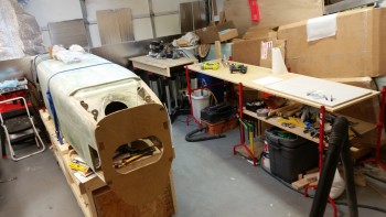
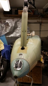
Yes, Gang, I’m calling it!  Chapter 13 is done!  Wow . . . although there were a lot of other related tasks, but not specific to the nose build, the nose & nose gear took close to 3 months to complete.

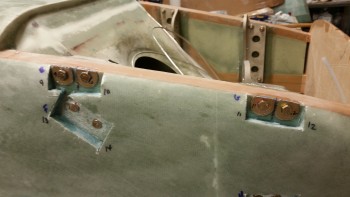
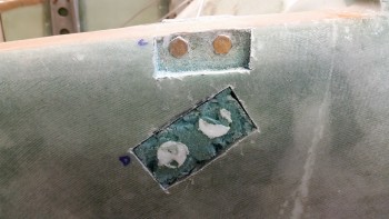
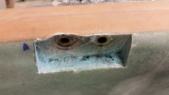
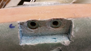
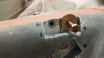
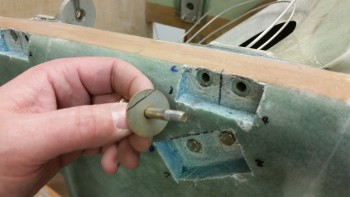
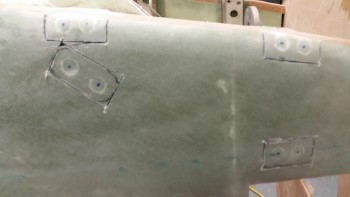
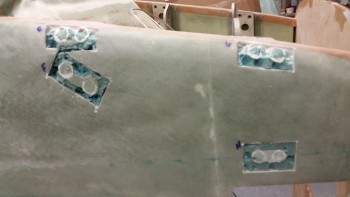
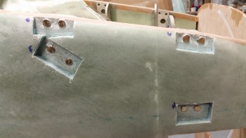
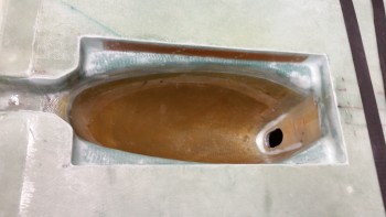
Today I started off with removing the Rivnuts that I used to secure the Click Bonds into place.  I would have used my thin standard nuts but I can’t find the bag of those, just like I still haven’t found the stainless steel hardware for the gear fairing.  I must have a thieving shop gnome who comes out at night & steals my hardware.  Either that or I’m going senile… nah, I have a gnome!

Removing RivNuts from Click Bonds

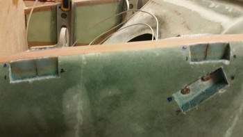
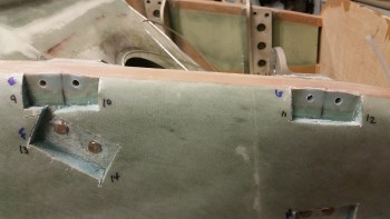
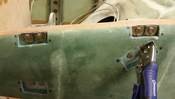
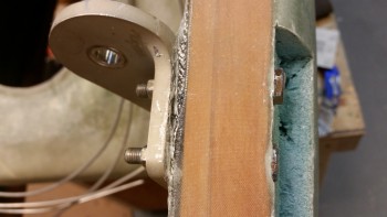
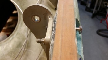
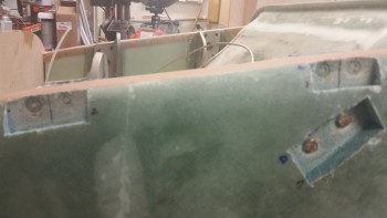
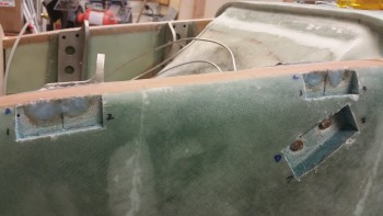
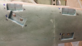
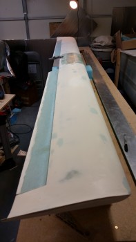
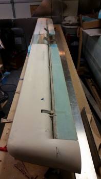
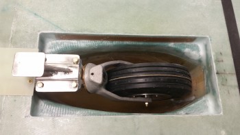
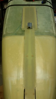
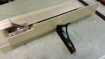
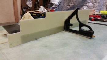
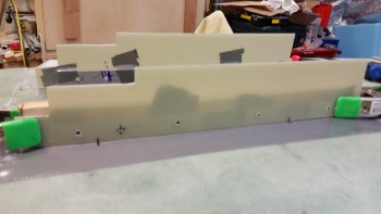
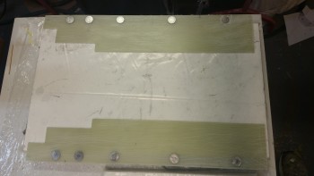
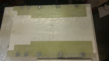
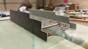
I then trimmed & sanded the nose gear doors and installed them on the fuselage.  This one sentence makes it sound like a 5-10 minute process, when in fact it took a good couple of hours to get both gear doors set correctly to lay down properly on the fuselage surface, and then to play nice together.  I did a lot more trimming, filing & Dremeling on the ends of the hinges to get them to set in the channel correctly.  In addition, I had to slot all the hinge holes a little to be able to adjust the hinges up & down.  I did this with a round file that is one of the toughest tools I have… it will grind down stainless steel like it’s butter!

Gear doors cut & installed

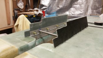
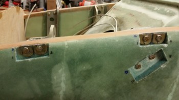
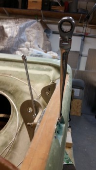
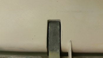
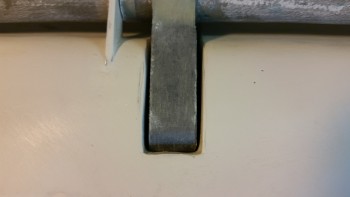
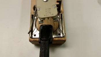
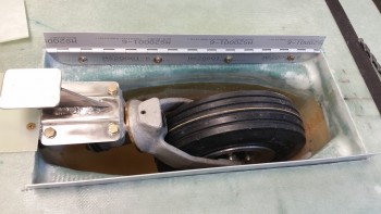
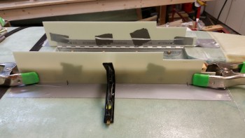
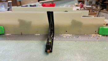
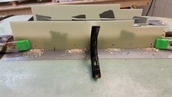
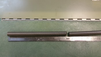
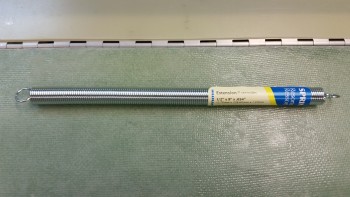
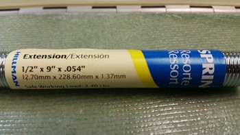
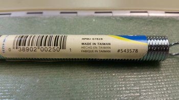
As you can see I mounted the spring but that is proving to be frustration personified!  I finally gave up because I got the spring installed, and then trimmed down a notch, and then reinstalled (repeat, repeat, repeat) so that the spring wouldn’t overcenter and thus not allow the doors to fully open when the gear goes down.  But by the time I got finished trimming the spring down so that the doors would pop open fully upon the exiting of the gear strut, the spring was too short to keep the doors perpendicular to the fuselage.  In short, my doors lean inwards when they are in the “fully” open position.

I spent about 45 minutes checking the forums, blogs, etc. to see if I could find anything, but I really didn’t.  I already knew that I was going to have to go the wire insert route (in addition to the spring, yes, which is also wire).  I emailed my buddies Marco (call sign “Capt Meatballs”) and Mike (call sign “BizMan”), but Marco was too busy laying up his CS Spar glass to help (ha!) and Mike is probably developing a complete A-Z engineered solution for me as I write this (ha!).

Regardless, I’ll work this as the information & advice rolls in.  It does work in the state it is right now, but not with any clean or elegant movements.

Gear doors cut & installed

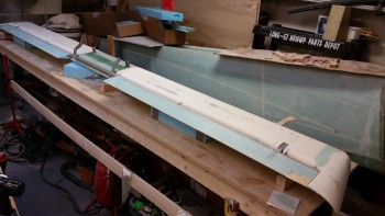
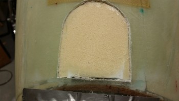
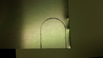
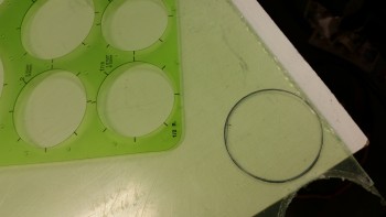
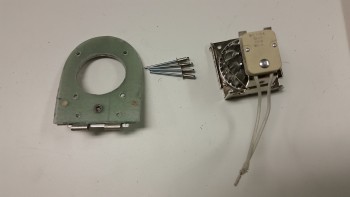
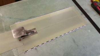
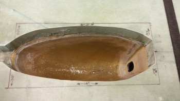
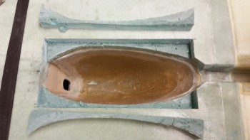
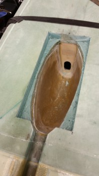
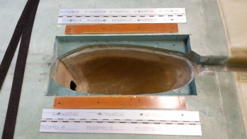
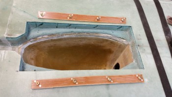
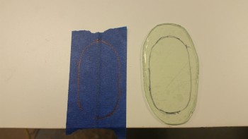
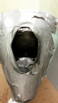
After spending a number of hours on the gear doors, I decided to set my sites on something relatively simple that I could kill with relative ease, and then feel both manly & productive!  I took my cardboard template (brown) of the nose wheel viewing window in the center strut of the instrument panel and made another template (white) with a little extra border in order to mount to the center panel strut.

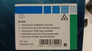
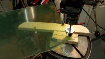
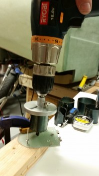
I then grabbed the sheet of Plexiglass [that I ordered from ACS as a backup to the Lexan just in case things got really bad trying to form the landing light lens cover] and marked it up with the larger template.

Cutting nose wheel viewing window

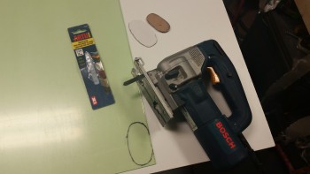
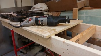
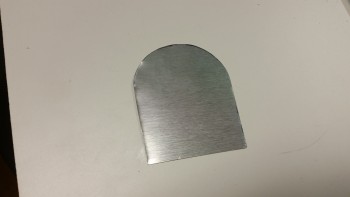
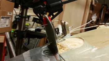
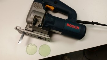
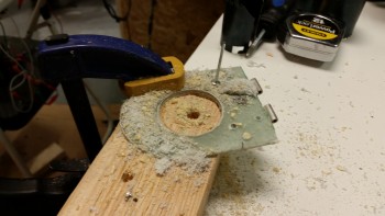
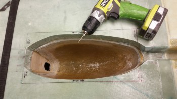
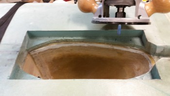
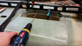
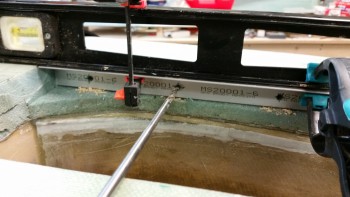
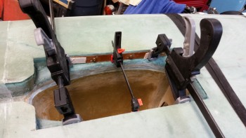
Then using my jig saw I cut out the Plexiglass nose wheel viewing window.

Plexiglass nose wheel viewing window

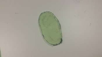
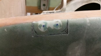
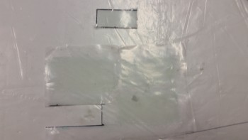
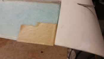
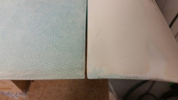
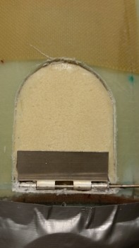
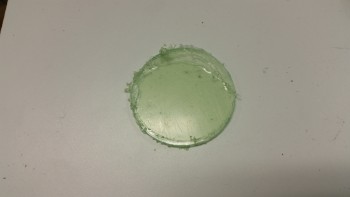
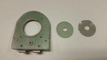
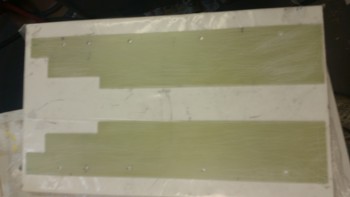
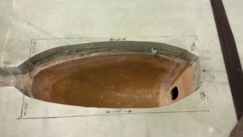
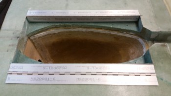
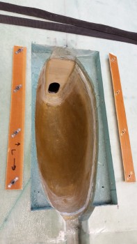
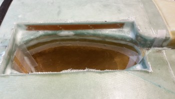
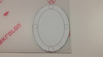
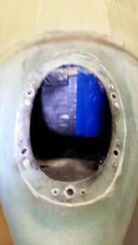
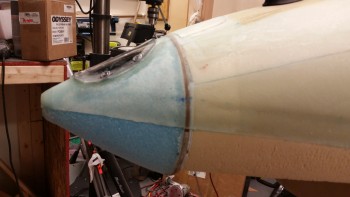
I then took some blue tape and marked an oval shape just slightly smaller than the actual viewing window frame outline.  In the pic below the Plexiglass viewing window piece only has the protective plastic on the back since the front side is ready to be mounted to the center strut frame.

Protective tape for viewing window

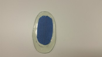
I applied the blue protective tape in place and then used 100 grit sandpaper to scuff up the border of the Plexiglass viewing window.

Border of wheel viewing window sanded

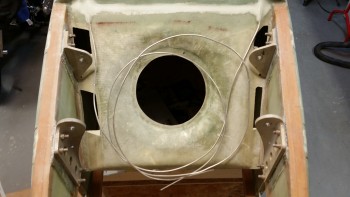
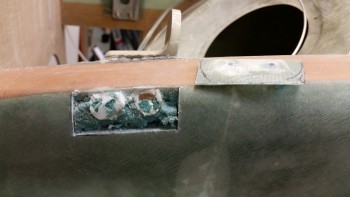
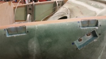
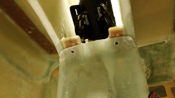
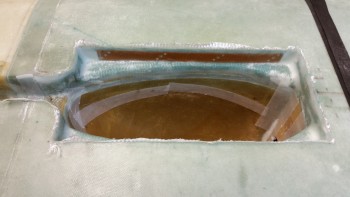
I then used some clear RTV silicone adhesive to mount the nose wheel viewing window to the center strut of the panel, which is of course located on the inside of the nose wheel well cover (NB).

Silicone to bond viewing window into place

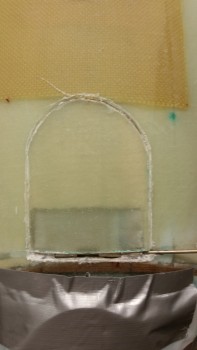
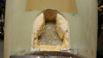
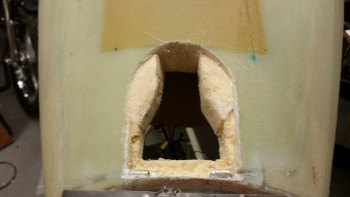
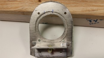
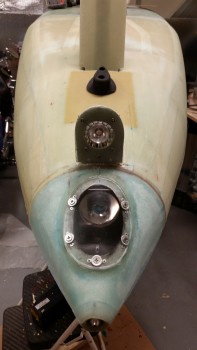
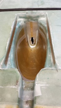
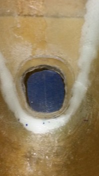
Fast forwarding ahead a couple hours, here’s the mounted nose wheel viewing window.

Nose wheel viewing window

I then stowed the Plexiglass sheet and pulled out the sheet of Lexan I picked up specifically for the landing light lens cover.  Unfortunately, I didn’t use enough forethought and bought 1/8″ thick Lexan instead of the 0.06″ thick that I determined was required as I was constructing the landing light mounting flange.

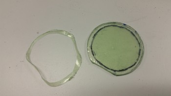
Regardless, I traced the outline of the landing light lens cover template onto the surface of the Lexan & then cut it out.

Cutting Lexan Landing Light Lens cover

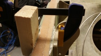
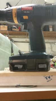
Since you can cold bend Lexan, I took my Lexan piece and tried my hand at it.  I clamped the Lexan lens around a PVC pipe, continuing to add clamps as I bent it more & more.  Since Lexan has a pretty good spring back towards its original shape, I was trying to get it as closed to wrapped around the PVC pipe as possible.

ATTEMPTING to cold bend Lexan…ha!ATTEMPTING to cold bend Lexan…haha!

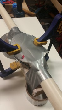
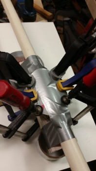
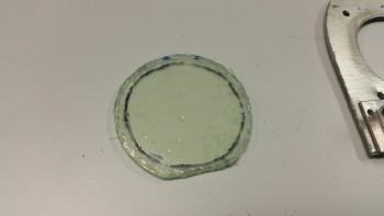
Well, of course the clamps could only do so much and eventually started slipping off.  I tried for a good while to keep the lens cover clamped but it became a little difficult.  I pulled the Lexan piece off the PVC pipe to check its curvature, which amazingly was NONE!

After all that!!! Nada!

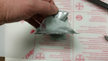
I then put the Lexan lens cover in a clamp and started hitting it with the heat gun (not shown).  I did this for about 15 minutes and was really blasting it with the heat gun.  I let the  clamped lens cover cool for a while and then checked it.  It actually held a bit of a curve, so I clamped it again and put it under a heat lamp while I started installing nutplates into the landing light lens cover mounting flange (see pic below).  About every 10 minutes I would clamp the lens down even more.

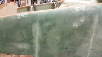
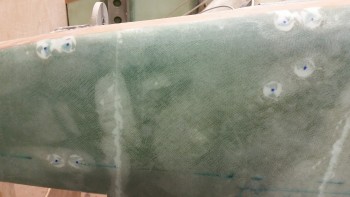
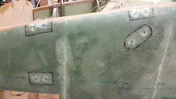
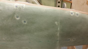
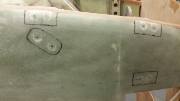
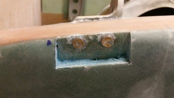
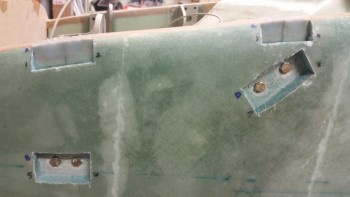
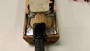
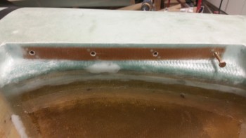
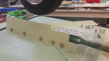
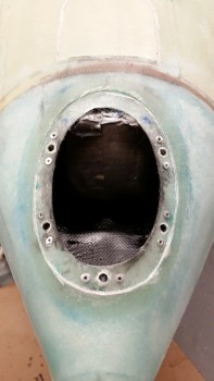
As far as the lens cover mounting flange, I started by installing the bottom center nutplate (in relation to the nose as it sits currently), and then added two more on each side.  I didn’t add a nutplate on the upper center part of the flange since I can’t get access to the back side of the flange due to the landing light.

Installing landing light mounting flange nutplates

Before I took the tape off the face of the Landing Light, I took the opportunity to touch up some spots inside the light bay with the flat black paint.

Touching up black paint in nose light bay

Nutplates installed & paint touched up

A little bit later, after the paint dried, I started pulling the tape off the face of the landing light.

Removing protective tape from landing light

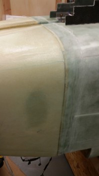
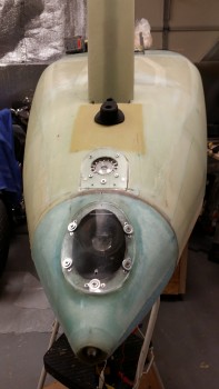
I then mounted the Lexan lens cover to the landing light mounting flange.  Now, the Lexan was slightly curved from my myriad of bending actions, but it was only curved maybe about 35-50% of what it needed to be to fit “naturally” onto the mounting flange.  So, since Lexan is some tough stuff, I simply (and literally…) bent it to my will!  I drilled & installed the bottom center screw first, then the upper left screw as shown in the pics below, then the upper right, the lower right, and then finally the lower left screw.  So, one screw at a time I mounted this sucker!

Laniding light Lexan lens cover installed!Landing light - detail view

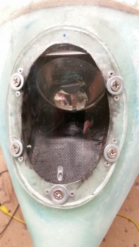
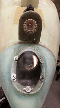
Here’s a side shot of the mounted lens cover.

Landing light - side view

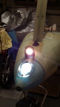
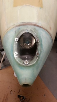
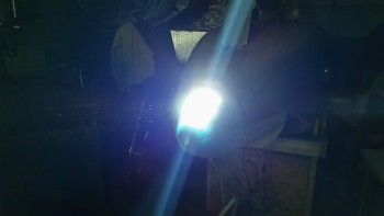
I then fired up the landing light to check out how it’s looking through the lens cover.

Ahhh!!! Soooo Sweeet!!!!

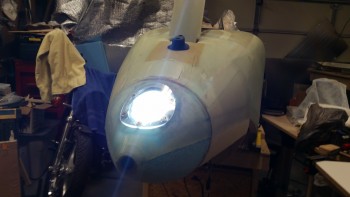
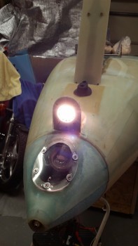
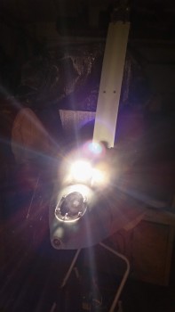
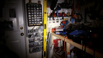
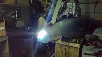
I then turned out the shop lights t see how the light illuminates in pitch dark conditions. Looking good!

Light test… with all shop light off!

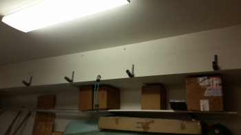
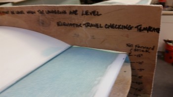
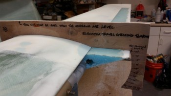
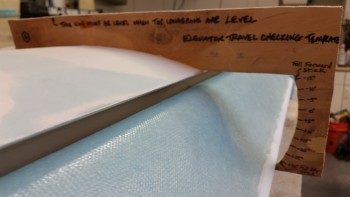
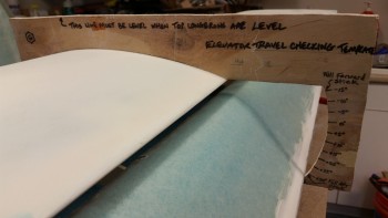
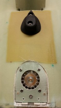
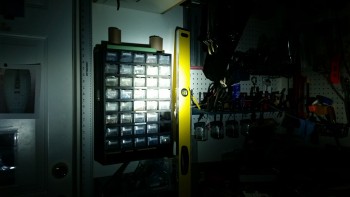
I shot a laser dot out from the pitot tube which hit level with he black handhold that you can see at the bottom of the yellow level in the pic, which tells me that there’s a good difference in angle as there’s supposed to be.

Landing light . . . very focused beam

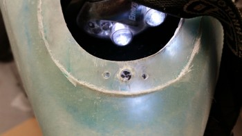
Here’s a closer in shot of the landing light, still with the shop lights off.

Closer in with lights still off

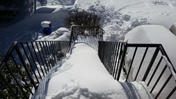
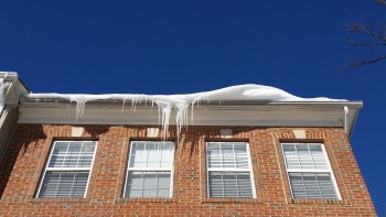
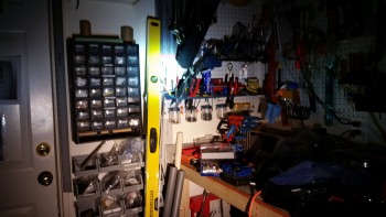
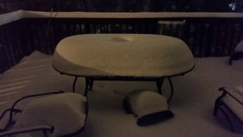
As I came upstairs after calling it an evening, I snapped a couple quick shots to show you all the winter storm we’re having here in Northenr Virginia tonight.

Snow storm!

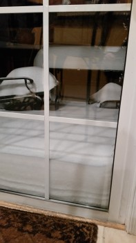
Quite a bit of snow, eh?!  So far we’ve gotten between 16-18″!

Wow … some blizzard, eh!

Tomorrow I plan on working on the gear doors if I get some info from my fellow builders.  I’ll also work on the Taxi Light interspersed with prepping to start work on the aft side of the fuselage (main gear, etc.).


Chapter 13 – Gear Doors Part 2

I started off today by pulling the peel ply, razor cutting & sanding down the cured wheel well glass layup from yesterday.  It looks good & I’m very pleased with how the layup turned out.

Cured & cleaned up wheel well glass

I then cycled the nose gear to make sure everything fit & clearances were good.  Again, it all looked good.

Checking wheel & strut fit

I took a bit of time digging out the plastic Saran wrap from the embedded K1000-3 nutplates.  I then tested the bolt holes with an AN3 bolt.

Exposed nutplate threads right side

It took a bit of trial & error to trim the corners of the lower hinge half to get it installed, but when it was finished it fit great.

Hinge trimmed & installed - right side

I also did the same on the left side hinge.

Left side hinge installed

After trimming the gear doors to fit, I took a shot to see how it all looked together… cool stuff!

Checking out how it all looks

Here’s another shot of the strut fairing & gear doors together.  I cut the gear doors a little funky so that they’d fit with the way I have the strut fairing configured.  If I had put some more thought into my planning, I may have realized that if I had the bottom edge of the strut a half an inch higher than I wouldn’t have to wrap the gear doors around the bottom of the strut fairing.  Also, you may note that the base for the T-shaped gear pedestal is exposed.

I’ll be honest, I definitely want gear doors since I think they enhance the look and are practical in keeping a good amount of cold air out of the wheel well, but they are a low priority for me so I wasn’t about to mess around with moving the microswitch on the nose gear actuator to increase the depth of the nose gear in the nose gear wheel well just to make the gear doors fit over this bracket.  So, being “efficient” I just cut a notch in the doors around the damn thing!  HA!

Gear doors & strut fairing

After a bit of sanding the edges to get the doors aligned I started prepping them to drill the holes for the mounting screws.  First, I checked to ensure I had enough clearance by checking the doors open at a right angle.

Checking spacing at right angle

Configuring for drilling mounting holes

I was going to hot glue the gear doors to the hinges to test the fit and swing of the doors, but found that duct tape held them in place fine.  I did have some final tweaking in the position, but no more than 0.04″ in any direction.  After messing with it a bit, I got the door & hinge geometry all dialed in.

I also marked thick crosshairs on the outboard side of the hinges that were visible through the gear door.  I then clamped both the gear door & the hinge to a wood crosspiece to ensure that my position was locked in while drilling the holes.

Gear doors duct taped for test fitting

I started by drilling some small pilot holes (left) and then moved on to drilling 3/16″ holes through both the gear door & the top hinge plate (right).

Pilot & main mounting holes drilled

Here are the 4 hinge bolt holes to mount the gear door to the hinge.  I also had a mark made for the gear door spring mount, but I had to double check a couple things before drilling it.

Door-to-hinge mount bolt holes drilled

I then drilled the bolt holes into the right side gear door & hinge.

Hinge mount holes drilled Right side

Below you can see I mocked up the gear doors with click bonds.  I actually messed around with installing the spring for a bit, but I haven’t nailed down my spring mounts yet and although pretty cool, it wasn’t working exactly correctly yet.

Clickbonds in place

After the gear door hinge bolt holes were drilled, it was time to glass the exterior sides of the gear doors with click bonds installed.

Gear doors sanded for layups

To make the gear doors stiffer, I planned on installing a ply of carbon fiber on each door.

First ply - Carbon Fiber

I then cut a couple pieces of BID to be the final protective and added strength ply of the layup.

Second ply BID

I then set the click bonds in place.

Click bonds in place

And then floxed them all in.  To help mitigate any galvanic reaction between the click Bonds & the carbon fiber, I slathered the stainless steel click bonds with flox.

Click bonds floxed in place

I then laid up the first ply of carbon fiber.

Carbon fiber ply layup

And then a ply of BID.  I thought this shot below looks very cool.

BID ply layup

I then added epoxy to the carbon fiber on the gear door at the bottom of the pic & finished up the first door.

Left gear door layup complete

Here are both gear door layups complete, with 1 ply Carbon Fiber and 1 ply BID covering it.

Gear door layups complete!

I also cut the spring that I installed and played around with for a few minutes.  I cut the spring the width of the of wheel well bay, which is 6.4″.  The spring I’m using is a stainless steel spring from McMaster-Carr (P/N: 9665K28).

Stainless steel spring cut at 6.4"

I bought the spring below a while back at Lowe’s to use but it’s not stainless steel, which is something that I definitely prefer.

Alternate Zinc spring from Lowe's

Here’s a close up of the dimensions & part number for this spring.

Closeup of Lowe's spring label

Closeup of Lowe's spring label

And a comparison of the diameter.  The Lowe’s spring is a little bit bigger in diameter.

Comparison of springs

Tomorrow I plan to trim up the gear doors & get them mounted.  I’ll then spend some time on finalizing the spring installation to get the gear doors working & check off Chapter 13 as complete.  IF I have time, I may actually get to messing around with the landing light as well!


Chapter 13 – Gear Doors

After a couple of hours of some much needed project admin organization I started on the nose gear wheel well doors.

I re-measured out the dimensions of the wheel well & double checked that all the lines were square.

Gear well marked for cutting

Since I would be cutting down an inch to remove the foam, I set a small drill bit in the drill at 1.1″ and made 3 test drills along each side to make sure I wasn’t going to slice a big hole into the floor of my fuselage when I cut out the sides of the wheel well.  Thankfully, there were no breakthroughs when I drilled my test holes.

Test drilling for depth

I then used my Fein saw to cut out the vertical and horizontal cuts.

Cutting out sides with Fein

I then popped off each freshly cut side.

Sides cut out with Fein saw

Here’s a shot of the freshly cut sides.

Sides cut out with Fein saw

I then notched the sidewalls 1/16″ in from the side using a router to embed the phenolic hinge mounting nutplate backers.

Trimming sidewalls with router

I then cut the hinges at 13-15/16″ long, to allow for clearancee inside the 14″ long trough.

Hinges cut to length

I then cut the phenolic hinge mounting nutplate backers & drilled the lower screw mounting holes into the hinges.

Phenolic mount backing plates

I then set the phenolic in place & temporarily mounted the hinges, one at a time, and drilled through the pre-drilled holes in the hinges to make the holes for the nutplates in the phenolic.

Drilling screw holes into phenolic

Here’s a closer shot of the hole-drilling in the phenolic.

Drilling screw holes into phenolic

Here are the phenolic hinge mounting nutplate backers after I riveted on the K1000-3 nutplates, 4 on each hinge mounting backer.  After pondering on the upcoming 2-ply BID layup to hold each hinge mounting nutplate backer into place, I realized that I needed to trim about a 1/4″ off the top of each phenolic backer to allow me to create a flox corner edge above the phenolic backer and under the edge of the bottom fuselage glass skin to give the new glass layups something to bond to.

Otherwise I would have to radius the edges of the new wheel well sides and overlap the glass at least an inch onto the bottom of the fuselage.  But clearly, with the hinges mounted to the sides, I didn’t want rounded edges since a nice 90° corner is what is desired for mounting these hinges.

Nutplates installed in Phenolic mount plates

I then prepped the foam in the side walls to allow room for each nutplate in the foam when the hinge mounting backers get floxed into place.

You can also see in the pic below the trimmed and sanded phenolic backers, an that I spent a good 30 minutes using the Dremel tool on the intersection between the nose wheel cover (NB) and the fuselage floor as well. After I finished smoothing out the added Ooops glass area & dead flox, I shaped the foam into a radius to allow the glass to flow smoothly from the new foam side walls overlapping down onto the NB sidewalls.

Finally, you can also see that I removed the foam from around the top underside “lip” of the bottom fuselage skin glass to create one continuous flox corner to give the BID layup an anchor to bond to & create a nice strong perimeter for this mod . . . no weakness allowed here!

Foam prepped for nutplates

And here are the hinge nutplate backers floxed & clamped into place.

Nutplate hinge mount backers floxed in

Since I was using fast hardener, things went pretty fast from the pic above.  I had to work quickly to get all the flox into the flox corner that went around the entire upper edge (in relation to the pic).  I then had to add both micro-slurry & thick micro paste to various areas, then cut the glass and start the layup.  It was fairly frantic at times since there were so many intricate steps, but I ended up getting it all glassed as you can see below.

Wheel well/nutplate BID layup complete

Here’s a shot of the final layup from the other side.  You can also see that I peel plied the edges of the layups to help mitigate the gotchas.  Trust me, if you’ve never had a fiberglass sliver sink into you, you’re not missing the experience.  I went to flick some foam off the bottom of the nose and caught one that went DEEP… it hurt more than the usual snag & I needed yet another band-aid!

Wheel well/nutplate BID layup complete

In addition to the wheel well sidewall layups, which includes the interior layup for securing the nose wheel cover (NB) to the fuselage, and in turn the Ooops glass heightening of the NB, the wheel well area is now all covered with 2-plies of BID, and the major glassing of the nose components making up the structural part of the nose is complete.

Out of curiosity I weighed the foam & glass pieces I removed from the sides of the wheel well at the beginning, and each was right about 0.65 oz.  I then weighed one of the phenolic nutplate assembly and hinge, which came out to 3.55 oz.  So subtract the 0.65 oz from the 3.55 oz gives 2.9 oz x 2 = 5.80 oz net total weight gain for just the phenolic nutplate assemblies & hinges.  I’m estimating that with the BID, epoxy, FLOX, doors & spring that this mod will add about another 1.2 lbs in weight.  I’d say more, but I would still be adding flox & BID to the wheel well even if I wasn’t going to add gear doors, but clearly just not as much of it.

Wheel well/nutplate BID layup complete

Tomorrow I plan on finishing the gear doors and then working on the landing light lens cover for a bit.