Chapter 22 – More stuff!

As most of you all know I’m pretty much back in the saddle as far as flying is concerned in my attempt to finish up my Instrument Pilot’s rating.  Unfortunately, I’m definitely not in the saddle where the build is concerned.  In fact, the horse is in the barn and won’t really be ridden for another month or two as far the build.

I have been occasionally taking a break from studying here and there to get a bit of planning and scheming in on some of the miscellaneous electrical stuff that I have yet to finalize.

So, I thought I would provide a quick update on some of the pieces-parts that I’ve found to help further my cause.  First off, I finally found a good, cheap basic heater fan resistor coil for my oil heat system.  I got this off of Amazon for about $5.  Not bad, and so far it looks like it will definitely work.

Oil Heater fan resistor coil

Here’s the backside of the oil heater fan resistor coil.  However, since it didn’t come with any specs I had test each of the coil circuits for their resistance values and create a truth table to verify what was what.  It took about 10 minutes, but I verified the entire circuitry of the heater fan resistor coil.

Oil Heater fan resistor coil

I also ordered a heated seat pad kit for the front seat and/or possibly both front & aft seats (if I can make it work).  The wiring is fairly straightforward and the whole thing will come in under 0.8 lbs. installed.  I think I mentioned it before, but I will be wiring both the heated seat warmers and the oil heat system through a DPDT relay so that only one system can be powered on at any given time.  This is of course to ensure that the charging system, main power bus, and/or battery isn’t overtaxed beyond the capability of my 40A alternator.

Seat(s) warmer kit

Finally, when I spoke with Rich at Aircraft Extras about adding new AG6 warning screens (shown below) to a couple of new chips for me, I added a bottle of canopy cleaner and a tire air nozzle extension to the order to optimize shipping costs.

Aircraft Extras order

Here are the 2 new AG6 chips that Rich programmed for me.  To be clear, he just didn’t simply program them willy-nilly, but went off a fairly detailed spreadsheet that I created for him that listed out the majority of the field parameters.

AG6 annunciators' updated chips

The 2 new AG6 chips include a verified screen description number to display Canopy “Locked” (versus simply “Closed”) . . .

AG6 Canopy Open Alarm

And an updated EZ binary version of Landing Brake Up and Down (versus the already programmed Landing Brake “On” and “Off”) . . .

AG6 Landing Brake Down Alarm

Along with 2 completely new alarm conditions and screen displays:  RAM Air Open and Closed (to ensure I close the RAM air scoop to keep FOD out of the engine) and IBBS Low Volts (IBBS-specific low voltage alarm to show the back-up battery is not charging or is under charged).  I had Rich program these alarm screens as yellow since they fall more in the caution category in my opinion, but I can easily change the colors later on if I want.

AG6 RAM Air Scoop Open Alarm

AG6 IBBS Low Volt Alarm

That’s pretty much all I have to report for now.  I have of course been making notes of any potential system updates or mods as I run across them, but for the most part I’ve either been flying or studying over the past week or so.

Chapter 22 – “Danger Will Robinson!”

As I mentioned before, sideline to getting back into the books and refreshing my tired mind on Instrument flying stuff, I’ve been cleaning up some electrical system stuff that is a natural result of integrating systems and devices together.

One such area of my electrical system is on the warning annunciators.  I decided to crack the code on just how these AG6 annunciators (again, I have 2) are programmed.  Well, the programming manual might as well have been written in Mandarin Chinese when I started, but after working through it bit by bit I finally got the swing of it.  The weirdest thing about these annunciators is that you only have one interface to program them, the button –also the annunciator screen– which makes things interesting.  There are only 2 inputs that the screen recognizes, akin to Morse code: a short press [<0.7 sec] and a long press [>0.7 sec].  It also recognizes the rate and combinations of these presses together (analogous to the ‘double-click’ on a computer).  Again, once I worked at it a few times the input was really a non-issue. Add a little patience and it’s actually something new and fun.

One issue I had was that I failed to realize that there was an online spreadsheet that had the codes that I needed to program (or reprogram) these annunciators.  My being remiss in having this critical document on hand was evident after a few telephone and email discussions that I had with Rich from aircraftextras.com.

AG6 Warning Annunciator Screen

With the spreadsheet in hand I was able to effectively program about 80-90% of the input screens that I wanted.  To be clear, I had the installation manual that described the entire programming process, but what I didn’t have was the spreadsheet that had the required codes to tell me what screen ID numbers to input for the warning screens that I wanted annunciated… until after talking with Rich of course!

AG6 Warning Annunciator Screen

Since the AG6, as with what seems like the majority of experimental aircraft products these days, is traditionally geared towards the RV crowd, there are some unique warning annunciator screens I would like that are not on the list of hundreds of screens already preprogrammed on the AG6.

After finalizing all the programming I could do, I determined that I needed 2 completely new screens and slight modifications to 2 other screens to provide me what I’m looking for in my warning annunciation scheme.  The 2 new screens are “IBBS Low V.” for my IBBS unit, and “RAM OPEN” / “RAM CLOSD” for my engine RAM air intake.

AG6 Warning Annunciator Screen

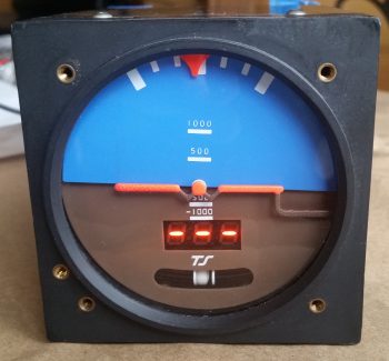
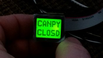
As for the pics above, I would like to point out that the top pic portrays the actual visual appearance the best of these 3 pics.  A brilliant, bright red light is really hard to capture with any of my cameras, and comes out looking orange and pale, and is not representative of its actual appearance (the same thing holds true for the indicators below).

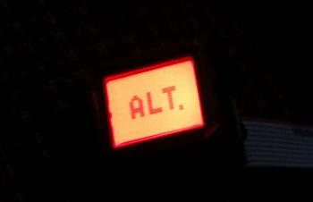
Finally, the top pic showing “CANPY CLOSD” is one that I want changed to “CANPY LOCKD” (there is a screen ID for the latter, but for some reason it too is showing as simply “CANPY CLOSD”).  There will be no “ALT.” screen, but rather “Low Volts” for the main bus low volt state (via the B&C LRC-14 voltage regulator).

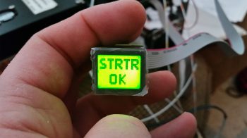
The last pic above is the annunciation that will show up for a few seconds immediately following engine start to show that the starter solenoid is not hung up (“hung start”).  As a reminder, a hung starter state is dangerous since huge current flow is rushing through the system from battery to starter and back unabated, which will fry the battery… with even possibly more bad smoking, fiery stuff to follow (Dick Rutan addresses this in CP #99).  To be clear, the more important screens are the red, flashing warning annunciations that will come and stay on until recognized with a screen press, or the warning state ceases on its own.  Thus, the entire time the starter is powered there will be a flashing red light depicting “STRTR ON” until it’s disengaged, at which point the green annunciator screen shown above will flash on.

Moving on…

As I mentioned the other day, in my quest to finalize both my warning annunciation scheme and my device ON/OFF indicators (below) I ran across a discussion from Paul Dye (Editor in Chief of KITPLANES mag) arguing that a simple, separate, non-EFIS or engine management system linked low oil pressure light should be incorporated into one’s lineup as a primary tell-all of engine health if your spiffy, modern glass cockpit goes Red-X on you.

I thought that for 2.3 oz it sounded like some good informational “need-to-know” insurance, so I bought this oil pressure switch from B&C to incorporate its alarm out state as an input into the AG6.  When the oil pressure is low (as in pre-engine start) a red, flashing “LOW OIL P.” annunciation will alarm (this is an adjunct warning light, not a replacement, of the EFIS-depicted engine instrumentation).

Oil Pressure warning switch

This oil pressure switch actually has 3 electrical connections to allow for a Hobbs meter to be wired up as well, if so inclined.  Here’s the back of the oil pressure switch, showing the N.O., N.C. and COM electrical connection posts.

Oil Pressure warning switch

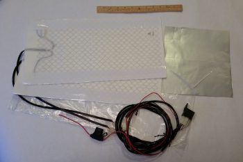
Lastly — something I’m extremely pleased with is these babies below that were delivered today!  Again, as I mentioned before, after I assessed my warning light system I decided that I would revise my original decision to run all but one pair of LED panel indicators through the AG6 annunciators, in order to make the AG6s strictly inflight/actual warning annunciators. Thus, those devices that I simply wanted to know were in an ON or OFF state would get downgraded to just LED lights again.

Now, I did order a myriad of LEDs in one my of Mouser orders, but my spidey sense told me there had to be something better out there.  After messing about online a bit here & there over the past few weeks, I found these.  They’re simple LED indicators for airline cockpit simulators that I found on Ebay (these are 737 panel indicators).  I wasn’t sure if they would work, but at less than $4 a piece, I figured I would pull the trigger and test them out.  I’m very glad I took a chance!

Non-warning ON/OFF LED Indicators

Again, the red and green indicators don’t photograph well, although the blue and amber lights are fairly good depictions of how they look.  These 4 items are the ones which I wanted their ON/OFF states communicated since –other than the fuel pump under my thigh support– I would have no real way of knowing if they are actually in an on or off state (yes, I could tell if the taxi light is on at night, but how about during the day?).

Non-warning ON/OFF LED Indicators

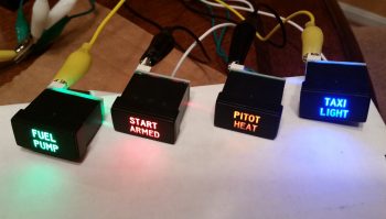
Best of all, these are low current and very lightweight indicators, with all 4 weighing in at less than 0.05 lbs.  I will run them through a dimmer so that their brightness can be dimmed at night, and turned up to their brightest during daylight flying.  One point of note is that I reserved the brightest LEDs (red & blue) for the ground op devices: START ARMED to indicate when the engine starting system is ready, and the TAXI LIGHT on indicator.  This leaves the FUEL PUMP and PITOT HEAT as the less bright, but still clearly visible, indicator lights for flight ops.  In addition, I reserved the only red light, denoting an actual real hazard, for the START ARMED indicator… since a swinging prop typically ensues immediately after it lights up.  So, although definitely listed in the “great-to-know” category, the other indicator lights (and their associated colors) do not denote hazardous states.

Ok folks.  Transmission ended, and back to studying for me!

Chapter 22 – Taxi Light Actuator Test

Today I performed a final test for the circuit that drives the Firgelli/Actuonix L12-S mini-Actuator for the swing-down Taxi Light assembly in the nose of the aircraft.

Firgelli/Actuonix L12-S mini-Actuator for Taxi Light

I actually set this up last night and messed around with it a bit.  Unfortunately, I had one power connection off so it wasn’t working in both directions with a simple ON-OFF switch. For a bit I thought I might need a more esoteric relay along the lines of a latching relay until I found my wiring miscue.

This morning I made the correction and Voila! . . . the actuator worked like a champ with the up/down throw of a simple ON-OFF switch!  The ON-OFF switch of course mimics the blue ON-OFF push button located at the bottom front of my Infinity stick grip.

I shot a short video to show how nicely this mini-actuator works, and show a bit of the wiring behind it, including the core part of this circuit: the DPDT relay:

From here on out for the next couple of months I’ll really be focusing on getting my Instrument Rating, so I’ll most likely not be posting nearly as much.  I will be prepping and working on the wheel pants when I get a chance, but as I’ve said before, the build will be my #2 priority for the first couple of months of this year.


Chapter 22 – A bit more electrical

Happy New Year!

Over the holidays I’ve been quietly working on the odd & end aspects of various areas of electrical stuff in my push to get as far as I can on finalizing the electrical system before moving on with the rest of the build.

Yesterday I finalized a 2-day process to figure out the wiring going out to the wing Nav, Strobe & Landing lights.  I had a quick but informative discussion with Dean from AeroLEDs and pulled the trigger on a couple different types of shielded 20 AWG electrical wire and some more connectors from Stein.  I also assessed & designed a reroute of my com radio antenna cables to get them away from the noisy wing tip light wire runs.

With final decisions made on the wing wiring, I finalized updating my wiring diagram for the Landing/Taxi/Nav/Strobe lights.  I also updated the wiring diagram for the AG6 warning annunciators, driven in part by my decision to only have actual warning annunciations communicated by the AG6 displays.  Thus, I decided to transfer the simple ON/OFF LED displays for those items that I merely want to know if they are in an on or off state (start armed, taxi light, pitot tube & fuel pump) off of the AG6s.  I ordered what look to be some high end LED annunciator buttons off of Ebay for these 4 ON/OFF indicators.  I’ll assess those when they arrive and move on from there.

I have one more item to report as for warning annunciators: as I was doing my research for what I should employ as simple device ON/OFF indicators, I ran across a post on the VAF forum from Paul Dye (Editor in Chief for KITPLANES magazine) arguing the merits for having a backup Oil Pressure warning indicator that was not integrated into the glass cockpit system… in other words, not reported by the EFIS or the Engine Management System.  I assessed this for a few days, and finally concluded that if I did have a catastrophic display outage and was looking at nothing but red “X”s on the EFIS displays that it would be nice to have ONE annunciator light to provide the overarching status of my engine health, and oil pressure is arguably (as Paul Dye so eloquently does) the biggest. For a weight penalty of 3 ounces, I decided I would incorporate this backup oil pressure status into my warning annunciation scheme.

Today I finally received my L12-S mini-actuator for driving the Taxi Light assembly deployment and retraction.  As you can see in the pic below I bought a number of ancillary parts that should facilitate the install.

Actuonix mini-Actuator & parts

Although I knew it when I ordered it, the tiny size of this actuator is really hard to believe until you actually hold it in your hand, which is exactly what I did!  Again, seeing this pic it’s not hard to believe that this thing only weighs 34 grams.

Actuonix L12-S mini-Actuator

Here’s a shot of the Taxi Light swing down assembly parts that I picked up with the L12-S mini-actuator.

Taxi light actuator hardware bits

I also decided that I was long overdue in doing a thorough ops check of the Trutrak 3-1/8″ ADI that I picked up off of Ebay from an RV driver as an attitude reference backup to my glass panel.  I did a quick review of the instructions and fired it up.  Since I had the GPS puck plugged in I wasn’t quite sure why I wasn’t getting the GPS track info in the window where the 3 lighted dashes appear.  Well, I got back into the manual, did a quick online search and still couldn’t find an answer.  Hmmm, did I have a bad unit that needs repaired?

I couldn’t ponder on it long since I had to run out and help a friend move some furniture (the bane of being a pick-up truck owner!).  Well, I arrived at the location a bit earlier than they did, so I decided to call Trutrak and find out the story on the 3 dashes.  It turns out that the 3 dashes are normal & that no track info is displayed until the aircraft is in motion…. Ok, another good instrument ops check!

Ops checking Trutrak ADI

Tomorrow I’ll test out my taxi light actuator circuit design & operations by wiring it up to the DPDT relay I have on hand.