Chapter 22 – Traffic Alert!!

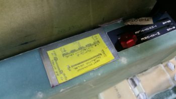
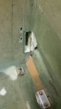
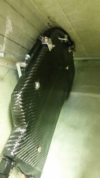
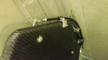
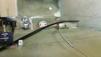
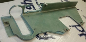
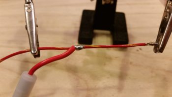
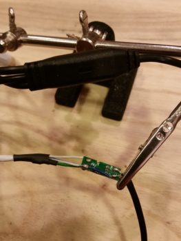
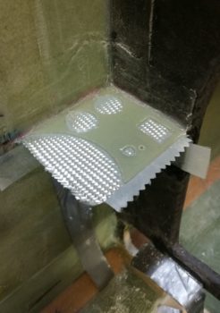
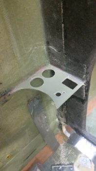
I ended up staying an extra day on my trip and got back today late afternoon.  I was a bit tired from yet another multi-legged journey and feel just a slight bit of a cold coming on (alas, I hung around a number of sickly folks….).  More of my woes include it being fairly cold out, so I decided to start back in on the build with something a bit “low key.”

As many of you probably know, every year Seattle Avionics has an outstanding Black Friday sale where they provide lifetime subscriptions on their data at nearly half price for all the major EFISs, including Garmin, Aspen, Dynon, AFS, and yes, GRT.  The map data they provide is geo-referenced sectionals, hi/low IFR charts, approach plates, and airport diagrams.

As to how good all this is, I’ll sum it up as someone said on the GRT forum:  The charts are ok, but zoom out to past a 100 nm view and they’re virtually useless. I suspect that having the ability to zip around the map with a touchscreen EFIS (ahem!) makes them a bit more useful… somewhat analogous to using an iPad.  The forum poster went on to say that the geo-referenced approach plates and airport diagrams more than made up for what the charts were lacking.

I still wasn’t going to pull the trigger until next year since, honestly, I still have quite a trek left to finish this airplane.  However, when I got the email (and I’m glad they sent it) that said this was the last year of their deep-discounted Black Friday sale, I decided it was time to reluctantly break out the wallet.  Moreover, having seen Black Friday sales in the past from other airplane related suppliers (ACS, Wicks) that are no more, I figured they weren’t kidding and for nearly half the price, I wasn’t going to take the chance that they were.

I started out by downloading Seattle Avionics DataManager Program that allowed me to pick what charts I wanted, including charts they offer for all of southern Canada, a bunch of Mexico, the Caribbean and the Gulf of Mexico… pretty nifty.

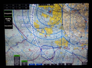
After downloading the data from the Seattle Avionics server, and then uploading it to a 32GB SanDisk thumb drive [which was a multi-hour endeavor to find and purchase] that needed to be pressed into service vs. the originally GRT supplied 8GB USB stick, I was quickly able to bring up the IFR low chart on my EFIS.  Again, pretty nifty!

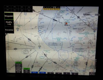
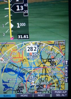
I then played around with the sectional chart for a bit.  BTW, the guy on the GRT forum was correct: anything out past a 100 nm resolution and these charts are really not very useful.

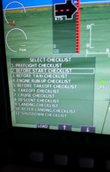
I then had an issue where I couldn’t load up the approach plates, so while I messed about with trying to figure that out I decided to build my aircraft checklists and load them up into my HXr.

When Marco bought the superb Long-EZ that Terry Lamp built last year, he tweaked the checklist for a much more logically flow.  He provided me with a copy and that’s what I used for the boiler plate to create these checklists.  I then spent quite a few hours (as I was slowly uploading all the chart data for the surrounding states in my area) tweaking and updating the checklists with items relevant to my specific configuration.

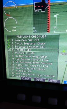
On the left is a list of all the checklists I’ve created so far, and on the right is an example in the Preflight Checklist of each item getting checked off as it is completed.  At first I wasn’t sure if I would like these on-screen checklists, and to be certain I will have a hard-copy version [that’s all I’ll have for the external walk-around part of the preflight], but I can see myself adapting to using these and not messing about with any physical checklist in the cockpit . . . especially when it ends up somewhere where it’s not supposed to be!

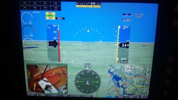
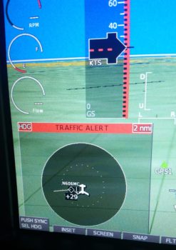
I wanted to show this shot of the right map inset (it can be located on either side, I just happen to keep it in its “default” location) with all the ADS-B traffic buzzing around.  I live a few miles south of DC’s Reagan National Airport, so not surprisingly it shows a lot of traffic.

Moreover, my being in the traffic pattern affords the HXr to showcase one of its really cool features that I’m sure I’ve discussed previously: when traffic enters into an area that I’ve defined in the settings, it lights up the left inset with a Traffic Alert, as shown below.  It will stay active as the left inset until the traffic has traveled outside those predefined distance parameters, at which point the inset will revert to what I had there before: typically an engine info screen detailing EGT and CHT data.

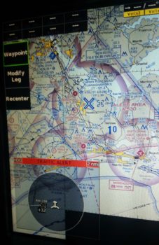
With the sectional chart up, I meandered my way down to the North Carolina coast where I plan to be living next year.  While “visiting” down there I got a visitor in the way of another traffic alert.  I love this feature so I grabbed another shot of it…  no more pics of these, I promise (in THIS post!).

As I was finishing up this post, Jeff from GRT called to help me out with the case of the missing approach plates (key dramatic music!).  Well, apparently I didn’t quite understand the process, and mind you it’s not specifically written down anywhere.  Thus is the plight of us GRT users… yes, the learning curve may take a bit, and what it can do is not always straightforward, but I am constantly amazed at how versatile these EFISs are… but I digress.

I was trying to LOAD the approach plates into the EFIS by copying them over from the USB stick, which I didn’t realized simply can’t be done.  Although I knew there was a lot of data, there is so much data that the EFIS merely reads it all off the thumb drive… much in the same manner, but way faster, as our Commodore 64 computers read the data off cassette tapes…ha!

Before Seattle Avionics came up with these nifty Geo-referenced plates, the only original method in play to get approach plates displayed on the EFIS (when GRT enabled the capability to do so) were PDF plates.  These PDF plates are still a viable option and they’re free, but not geo-referenced.  So the menu item still shows “copy” as a means to bring approach plates (ahh, but only PDF plates) onboard.  For “chartdata” plates, in reality one simply just needs to go select an approach at an airport and load ‘er up (I had tried this early on but it didn’t work… it of course worked fabulously while I was on the phone with Jeff from GRT, so he called to confirm that there was actually no problem… haha!)  Oh well, at least its working . . .

Below is a shot of a quick Direct-To flight plan I ginned up down to Chesapeake (I hope Marco reads this to know I’m coming to visit!) and the approach plate that I just learned how to effortlessly pull up.

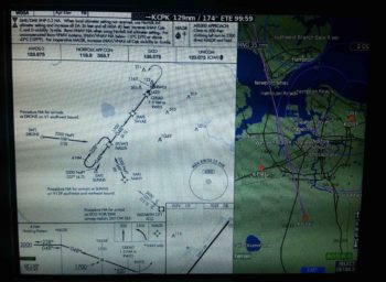
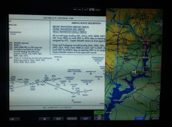
Here’s a shot of a STAR (Standard Arrival Route) plate that I pulled up for BWI.  The EFIS provides a way to turn, pan, zoom, etc. the plates to ensure you can see what you want. There are also other EFIS views with the approach plates (e.g. just the plate) if I wanted to set it that way, here I was just confirming that they worked.

Ok, so with the EFIS data and checklists squared away, tomorrow I will finish finitely planning out my build tasks over the holidays and for the next couple of months.


Chapter 22 – Video Switch Test

First off, as I mentioned a couple of days ago, this will be my last post for a almost 2 weeks as I head south to visit friends in NC for the Thanksgiving holiday.  In addition, I’ll be taking a load of household goods to storage as I slowly transition to North Carolina. Over the next few months, my house will look more and more as it did in Germany… the bare minimum for living and all the rest a Long-EZ building facility!

As for the build, if you recall I purchased a small USB module from GRT that allows to me port video into the EFIS from a RCA-jacked micro video camera.  The inset in the lower left corner of the EFIS shows you my previously reported successful test with this added feature.  Not bad.

Again, I went on the AeroElectric Connection forum to see about creating an auto-switching device that would take video feeds from multiple cameras and output them via a RCA jack to the USB EFIS video input module.  Moreover, this new device needed to cycle through the cameras automatically, every 3-5 seconds (or whatever timeframe the user chooses).  Finally, it also allows for the user to toggle straightway to the camera wanting to be viewed without having to wait for the cameras to cycle through.

Well, Eric Page on the AEC forum has been gracious enough to take on this project, and along with Alec Meyers, has been working to build this video auto-switching device.  He did, however, need some data off an EFIS with the video capability (e.g. mine) and to do so it required I purchase a cheap video switching unit off Ebay.

In short, Eric & Alec needed to know if the EFIS would lose synch with the video feed if it were switched from one video input to another.   I’m happy to report that other than about less than a half-second distortion in-between, the video switches from one to the other with no issues.

I’m also glad I could fit this test before I head out on my sojourn to NC.  With that, I’ll see you all on the other side (as in, December).

Happy Thanksgiving!


Chapter 22/24 – The heat is on . . .

Not literally on… in the airplane that is.  But definitely on the list as the primary thing to work.

Ok, enough banality!

I started off today installing the push-pull cable on the top of the heat exchanger (HC) for the heat restrictor butterfly valve.  I quickly realized that the attachment assembly on the valve lever arm was not happy with the offset alignment I had with the Adel clamp set a bit more inboard, so I whipped up a little L-bracket to allow the Adel clamp to be mounted on the top edge of the HC vs the side.  It worked like a champ.

I then set about determining where the #2 Clickbond should get mounted on the surface of the heat exchanger.  I played with the alignment for a bit, and ran through a number of maintenance and troubleshooting scenarios in my head, all requiring the HC to be removed.  This mandated in my mind which side the cable needed to go (on the forward side so that by simply removing a cotter pin it frees up the lever arm so that the HC can be removed).

After determining where the Adel clamp would go and the configuration of the cable run for the fresh/heater air valve, I sanded down the area around it approximately 2″ x 2″.

I then 5 min glued the Clickbond in place and set it under a heat lamp.

After the 5-min glue cured, I then glassed the Clickbond in place with a ply of BID covered by a ply of Carbon Fiber [Yes, I know the weave is not aligned with the original CF weave, but this was the only spare carbon fiber I had on hand and I wasn’t about to waste any by cutting it off the roll…]

Here is the mounted and glassed Clickbond…. jumping ahead a couple of hours.

I then finalized my design for the 3-lever heat/air valve panel that will get mounted in the top middle of the left armrest, just aft of the throttle quadrant.

I then cut the top surface of the mounting plate out of 0.040″ thick 2024 aluminum.  As you can see it extends out further than what will be seen through the hole that I’ll cut into the top of the armrest.  I’ll mount 4 nutplates in the corners of this plate and mount it to the bottom of the armrest so that I can then unscrew the mounting screws and remove the plate from the armrest whenever the latter needs to be removed.

Since I had the sheet of 0.040″ thick 2024 aluminum out, I went ahead and cut the 3.3″ x 3.5″ plate for the 2 “Mag” switches (we’ll say, although both are electronic ignition) and the master switch.  As you can see by the pic, these switches will get mounted just forward of the control stick on the right armrest.

I then marked the area to be removed from the top of the left armrest for the 3-lever heat/air valve panel.

I then cut out the area using the “Fein” saw.

I then spent some time developing my plan for the actual cable runs coming from the heat/air valves to the 3-lever heat/air valve panel.  Yes, developing mods and incorporating all of them in one place like the left armrest can definitely be a slow process at times.  But I think a very necessary one in deconflicting all these components that are to be mounted. So often one decision begets another one, and even more so it may countermand a previous decision.  It’s all a balancing act when cramming this much stuff (grant it, stuff I think is the right stuff to have on hand) into this bird.

For example, having just really dug deep into my cable runs, I know have to reassess my mounting location for the fire extinguisher.  I may be able to simply move it to one side or the other, but right now it looks like I’ll now have to remove it from the armrest completely. I think I should be able to still mount it in the location I chose, but now the variables have greatly expanded again on where the fire extinguisher may possibly need to get mounted.

Ok, back to the actual build.  I used a bit of the flox that I made up for mounting the click bond to the HC for helping to secure the 2 crimped aluminum cable ferrules that attach the valve cable to the valve plate on valve #3, the Pilot/GIB air distribution valve.

[NOTE: I made a major boo-boo in that I measured the throw of the top edge of this valve at 2.3″, which is what I used to design the lever slot for the Pilot/GIB air distribution on the 3-lever heat/air valve panel.  However, a bit later when I mounted it, I determined that the cable geometry would work better if mounted it lower on the valve, closer to the fulcrum. When I tested out the valve cable runs a bit later (below) I then realized the cable only has a travel of 1″ since I relocated the cable attach point on the valve plate.  Oops!]

I then drilled the holes for the #1 and #2 valve cables (the fresh/heater air valve and heat restrictor valve, respectively) into the pilot seat back right next to where the duct traverses the pilot seat back as well.  The #3 valve cable actually travels through the duct until it exits out.

I prepped the cables and Adel clamps on the HC for valve cables #1 and #2, and installed valve #3 with the cable attached right to it.  I then mounted the GIB heat/air ducts and the HC in place (temporarily).  I ran the cables through their respective holes into and through the pilot seat back.

Here’s a bit closer look at the valve actuation, cables and securing Adel clamps on the HC. Plus, you can see the cable runs through the pilot seat bulkhead.

I then configured the cable for valve #3, which travels through the duct for about 6″ then, again, exits out of the duct shortly after it enters into the pilot area.  To be clear, the cable conduit only barely enters into the duct via the rubber grommet, so the 6″ of cable in the duct is just the wire, not the entire cable assembly.  This helps limit any negative impact on the volume of air traveling through the ducts.

Here’s the final shot of the evening, with the 3 heat/air valve cables coming into the pilot area under the left armrest.  I have to say, it was a good feeling crossing things off my 3×5 card task lists that I made up months and months ago….

I won’t get much farther than this since tomorrow is packing day.  I don’t think I’ve advertised it much, nor mentioned it on this blog yet, but I am in the slow process of moving down to North Carolina.  I say slow because my priority is still to finish this airplane first, if possible, before completing the actual move sometime next summer timeframe. Thus, tomorrow I’ll pack up a bunch of stuff, then Thursday I’ll load it up in a trailer to take down with me on Friday when I leave.

I’ll update my blog when I’m down there, but in general my plan is to give myself one more week to finish installing cockpit components after I return, with my focus back on the GIB area and the nose area.  After a week, I’ll hard reboot into working on getting the lower engine mount extrusions glassed & mounted in place, the engine mount itself drilled and installed, and then after I configure the few components mounted in the hell hole, glass the firewall onto the fuselage.  Then comes the prep for the top nose and canopy build, which will be a concurrent build to get the lines smooth all the way from nose to tail.  Shortly into that prep, I will be building my engine and bringing it home.

Then the fun really begins!


Chapter 13/22 – More pilot area stuff

Today I had the goal of getting the inside & outside of the top armrest cupholder ring glassed.

I started off by creating some mini-trenches at the top & bottom edges of the inside armrest foam where it meets the top and bottom glass.  I only really did this on the aft side of the cupholder ring since this foam has some mass to it.  The front side of the ring is just a narrow fragile piece of foam with a bit of glass on the top & bottom surfaces.

A bit later you can see that I had successfully glassed a ply of BID on the inside of the left armrest’s cupholder opening ring.

Once the internal armrest cupholder ring had cured, I glassed the front external side of the ring with 1 ply of BID where it mates with the heating switch panel. In addition, I peel plied both of these layups.

While I was waiting for one of the cupholder ring layups to cure, I quickly drilled a 3/8″ hole into the fuel vapor sensor mounting bracket to mount the handle for the nose hatch latch release.  I had originally labeled and clear coated a red T-handle to use for this function (below) that I still really like, but it just doesn’t fit well on the right side and mounting it on the left presents too much of a hassle to get it mounted, and specifically to get the conduit where I need it to go over onto the right side.

I then installed the smaller round nose hatch release handle in the fuel vapor sensor mounting bracket.

I then mounted the fuel vapor sensor to ensure there was no conflict of space.  Clearly I still need to label my new nose hatch latch release handle, but I think this will work out fine.

I then got to work figuring out the size and configuration for the cigarette lighter charger bracket in the corner just forward of the lower instrument panel bulkhead and on the left side of very front edge of the nose gear cover (NB)…. all just to the left of the nose gear viewing window.

After getting a paper template made out of a 3×5 card, I then transferred the shape to a 1/16″ thick piece of G10.

I drilled the hole first, then cut the bracket out of the G10 stock.  I then test fitted my new bracket in place.  It looked good, so I 5-min glued it in place.  When the 5-min glue cured, I then micro-filleted the edge where it mated with NB, and glassed the top surface with 1 ply of BID.

The pic below right is after the layup had cured, and I pulled the peel ply, razor trimmed it and cleaned it up.

I then test-fitted the cigarette lighter charger into its new mounting bracket.

Below is another shot of the new cigarette lighter charger installed at the base of the instrument panel bulkhead.  Now, the underside sleeve of this charger is actually a bit too wide in diameter to fit comfortably under the bracket, so I’m going to have to kick the hole outboard about 0.1″ to get it all to install smoothly.

I wanted the cigarette lighter charger in this location so I could use it inflight, both with the bigger old style charging adapters, and also with a USB charger insert.  Another major factor for picking this spot is that I wanted easy access to this charger specifically, since it will be wired to the battery bus.  Then, when I want to charge the battery, I simply just take the cigarette lighter charging adapter that I have for my charger and plug it in…. EZ PZ!

Friday I’ll be heading to NC for the Thanksgiving Holiday, so over the next couple of days I’ll be working less and less on the build.  However, once I get back I plan to hit it really hard again!


Chapter 8/24 – Small layups…

Today I started off by heading about an hour north to help out some friends do some household repair stuff.  I was there about 4 hours before returning back home, so it knocked a good half a day off my build tasks.   Plus, I have to admit I was exhausted when I got home so I took a good nap.

Before I left to help my friends though, I was able to configure both USB thumb drives for my respective HXr and Mini-X EFISs.  I then upgraded the software on my Mini, which is something that I haven’t done since I bought it in 2014.  I also backed up the configuration of each box to its respective thumb drive in case I need to reload my specific configuration of either EFIS for whatever reason.

After my nap, I got to work doing some small layups.  I had planned on doing the first one before I headed up to help my friends so that it would be curing, but didn’t get a chance to do so.  It was a real simple layup: just 1 ply of BID, securing the top part of the parking brake handle mounting bracket to the left side of the nose wheel cover (NB).  I used a floxed fillet as well, then I peel plied it.

This is a number of hours later after I pulled the peel ply, razor trimmed the excess glass, and then remounted the parking brake handle assembly and cable.

Concurrent with the layup above, I also micro’d the foam, created thicker-micro’d edges and glassed in a ply of BID on the very front, top, interior corner of the left armrest.  I peel plied this layup.

I also did pretty much the same thing for the heat/air duct plenum clearing notch I made in the inside of the left armrest at the bottom center of it.  I did not peel ply this layup though (although when I cleaned it up after it cured it ripped some fibers loose on the edge, so maybe I SHOULD have peel plied it!).

I then spent well over 2 hours updating my electrical diagrams and printing out the freshly updated ones.  I did a fairly significant overhaul on my heating systems diagram before I printed that one out as well.  Tomorrow I’ll get back to it!


Chapter 8 – Parking brake done!

Today was one of those days where I didn’t seem to get a lot actually done, but I got a lot of stuff figured out . . . which is also important.

I started off by pulling the peel ply from last night’s layup, razor trimming the layups and then cleaned them up.  I have to say they all came up pretty good.  Since I added glass to an area that I had been trimming a lot for clearance, I then test fitted it to ensure I still had the proper clearance.  It was a little tighter, but it still fit fine.  I think if I sand it down well it should fit very nicely.

I then worked a fair amount more on the parking brake.  I’m sure this may be the bane of my build for many builders/readers of this blog, but it’s one of those things to me that I should work now since I have access, and once the airplane is done it will be a nice extra to have.

I took another 20 minutes to carve out about an inch more of the 1/4″ Nylaflow conduit buried under glass and micro to free it up so I could get the slope angle right from the conduit to the parking brake T-handle bracket.  Once I got it right, I then 1-minute glued it into place, clamped it, and let it cure a good 10 min under a heat lamp while I prepped for the 1 BID layup.

I cleaned up the excess glue and then filled in the gaps around the now exposed –and trimmed– 1/4″ Nylaflow and the nose wheel cover (NB) with thick micro.  I then laid up 1 ply of BID over top of it, and set up a heat lamp on the layup.  I didn’t bother peel plying this layup (I know…crazy!)

Here’s a shot a bit later when it was cured.  I didn’t get an exact alignment between the Nylaflow conduit and the parking brake handle assembly, but it’s close enough and causes zero operational issues.

Here’s yet another shot of the final install on the parking brake T-handle.  Obviously, I like this location, and it works well for me.

I then spent about half an hour using a piece of cardboard to make up a template for my parking brake engagement panel LED indicator lever switch mounting plate.  This will mount over 3 of the 4 screws that were used to mount the NG8 plates to the inside of the left NG30 plate, at the nose wheel pivot mount.

I then transferred the dialed-in template to a 1/16″ thick G10 plate and cut it out.  I then slowly drilled the holes one by one to allow it to fit onto the exposed NG8 screws, and then once I got the upper 4-40 switch holes drilled (small holes, upper right), I then drilled 2 x 5/8″ lightening holes on the lower side.

I then labeled the switch.  I also verified, cut, terminated and labeled the wiring running to/from the parking brake engagement panel LED indicator lever switch.  I then mounted the bracket and switch combo and verified the switch functioning and angle… it all looked good so far.

Below is the switch in the closed, parking brake and LED indicator OFF position.

In this shot, the parking brake has been engaged, which opens the switch and closes the circuit, turning the LED indicator ON.

Finally, here’s a closeup of the parking brake engagement panel LED indicator lever switch and its mounting bracket.

During the process of wiring up the parking brake engagement panel LED indicator lever switch, I also verified my panel LED indicator lights Push-to-Test button operation, circuit design and configuration… and the panel indicator lights dimmer function as well. Tomorrow I have to help some friends out with some household maintenance stuff, but I should be able to continue on with my in-cockpit configuration quest.


Chapter 8/24 – Parking Brake: ON!

I started out today by pulling off the huge pile of weights that I had encased the left armrest with to keep all the mounting brackets aligned properly.  I then unscrewed and removed the left armrest.  I cleaned the protective tape off the edges of the armrest, then assessed the damage.  I think the heat lamps made the flox flow a little a bit more than it would have in a low-to-mid-70 degree shop.  Still, the 4 mounting brackets were on nice and secure, and that’s the main thing I cared about.

I was heading out to meet some from friends for lunch, so I quickly remounted the left armrest and then got to work laying up 2 plies of BID over the taped up part of the cupholder that was protruding out of the slot on the left armrest.  I then peel plied it and set a heat lamp on it since the shop is a bit chilly.

About 5 hours later I returned home, pulled the peel ply off and cleaned up the layup.  I was going to take another picture (uh, no joy) so there is no confusion on what I did, but what you’re looking at along the side of the left armrest is not the cupholder as before, but the new side of the armrest covering the cupholder.  It just so happens that at the point of where the cupholder is located, the side of the armrest just happens to be 2 plies of BID thick.  This layup not only serves to hide the ugly cupholder, but it greatly increases the strength of the very forward part of the left armrest.  In addition, it will allow me a much easier time when it comes to painting this area.

As I pointed out last night, when I floxed the left armrest mounting brackets into place, I also floxed on a bracket for the parking brake handle.  Well, here is the cured bracket and a test fitting of the parking brake handle.

Before I got in to test the ergonomics of the parking brake handle, I trimmed the bracket a fair bit closer to the mounting hole in the bracket, and curved the bracket into a half circle shape.

I then prepped the front seat to climb into the fuselage.  I would like to point out that the pic below is a bit historic for my build in that it’s the first time for my plane that the left & right armrests are bolted into place, and that the pilot’s seat thigh support is in place as well.

I then tested primarily the fit of the parking brake handle and its associated mount.  I love the location because I can’t accidentally engage the parking brake without –again– loosening my top shoulder straps and then leaning forward to grab the handle.  Plus, there is zero interference with my left leg.

As I was sitting there, I assessed possible locations for the nose hatch cable release handle and the pilot headset jacks location.  I originally was going to mount the nose hatch cable release handle on the other side of the nose wheel cover (NB), but since the right leg hole is tad smaller than the left, I decided that I’ll either mount forward and above the existing parking brake handle [if I use the T-handle] on the left side as well, or over on the right side of NB but using a much smaller pull knob…. much to decide.

Here’s a closer shot of the parking brake handle location and its clearance with my left leg.

And one final shot of the parking brake handle’s mounting location.

My last act of the evening, that took just shy of a couple hours, was to cut and remove the foam adjacent to the inside glass to created micro corners in the cupholder ‘U’-shaped area on the inside of the left armrest.  I also shaped a micro corner in the aft side foam of the small flat area at the very front of the armrest (left in the pic below).  After applying the appropriate micro, I then laid up 1 ply of BID at the front flat edge of the armrest, and along each side of the cupholder ‘U’ overlapping onto a ply of BID at the very bottom of the cupholder ‘U’.  I then peel plied the layups and set the heat lamps up to help them cure.

Tomorrow I plan on finishing the minute layups on the front side of the left armrest and move on towards working the middle and aft area of the armrest.  I’ll continue to work cockpit component configuration and installations as well.


Chapter 22/24 – What…more sanding?!

I started off today receiving the package from GRT with the USB video module that I discussed in yesterday’s blog.  I looked it over a bit and noted how lightweight it is.

I then made it even a little lighter by summarily lopping off the left & right audio feed jacks since I know I won’t be using them in my configuration.

Of course I couldn’t resist trying it out, so I hooked it up to my 4-port USB hub, connected the camera and then fired up the panel. Within 2 pushes of a button I had the inset showing what the camera was viewing.  Awesome!  Especially since there was no software configuring or loading required.

Within the next few days I should good a manual video channel switcher normally used by gamers that I got for a few bucks off of Ebay.  I’ll use that for some testing and report the data back to the guys developing the video auto-switching module on the AeroElectric Connection forum.

A sideline benefit to firing up the panel and checking out the new video capability was that I also got to power up the Dynon Intercom for the first time.  Now, I didn’t do anything with it to test it out, but I didn’t see any sparks, flames or smoke, so I’m going to call it good for now!

I then went to the shop and spent well over an hour dialing in the left armrest, focusing on its fit & interface with both the heating switch panel and, yes, the cupholder.  After getting the fit as close as I could, I decided that I needed to lock it into position by installing some mounting brackets –4 out of the 5 identified mounting bracket positions so far– to keep this thing from going all willy nilly on one end while I’m trying to do something on the other end.

Before I got deep into the armrest mounting though, I only had less than a couple of hours to make a lot of noise (I live in a townhouse with a STRICT homeowners’ associate that has a tizzy if I make noise after 10 pm).  One of those noisemaking tasks was to trim back the Nylaflow, glass and micro about 4″ so that I could mount the parking brake handle farther forward at the left side base of the nose wheel cover (NB).

I originally planned to have the parking brake handle installed adjacent to the nose wheel viewing window on the left side of the center panel strut, and the nose hatch release T-handle on the right side.  After assessing it for a while, I wanted it farther forward to get it out of the way during flight ops, and plus I wanted to make it so that I had to unbuckle my shoulder harness and lean forward to get to the handle…. which of course leaning forward is infinitely easier to do in a Long-EZ with the canopy open.  So, in short I’m saying that for both T-handles I wanted to ensure it was no-kidding ground ops thing.

After making a bunch of noise by ensuring that I could move the parking brake handle conduit, I then made a bit more when I trimmed the cable sheath on the parking brake cable assembly with the Dremel tool.  I cut a piece each of angled aluminum and 7-layer glass bracket stock for 2 more mounting brackets for the left armrest.

I then started making quite a bit less noise by simply using the drill to finalize the mounting brackets for the left armrest.  I made up one bracket for a #10 screw, and the other a bit smaller for a #6 screw.

I then prepped the left armrest by taping up the edges in the immediate area of the mounting brackets, and then attaching the brackets in place.

I then whipped up some flox using fast hardener and floxed the left armrest mounting brackets into place.  Although just about each one needed some type of persuasion with a heavy dumbbell to keep it in place.

Also, to be clear, I have a few more mounting brackets I’ll need to install on the left armrest, this is just round #1.  [BTW, the left armrest is at the very bottom of the pic, seat bulkhead is on right side]

Here’s a shot of the wheel well cover (top left) and front side of the panel.  I have the heat lamp shining primarily on the left armrest’s very forward mounting bracket that is attached to the aft side of the lower left instrument panel (lower right corner of pic).  Since I had some leftover flox, I very quickly finished prepping a small bracket I had cut from the 7-layer glass bracket stock I made a while back for the thigh support CAMLOC fasteners.  I then floxed it in place on NB (middle left of pic) for use in securing the parking brake handle.

Tomorrow I’m meeting some friends for lunch over in Maryland, so it will probably be a bit shorter build day.  But I will try to knock out as much as I can.


Chapter 22/24 – Off the rails!!!

Today I made a hard right turn in regards to my current tasks to get the cockpit component installs squared away now, so I don’t have to do them later after the install sites are buried underneath top nose foam/glass and/or behind the strakes.

I started off today with the intent of just knocking out wiring up one of micro-video cameras with an extension length of wire (a run to get from the camera which will be positioned just forward of the fuel site gage to behind the instrument panel). Why today, you may ask…. well me digress just a bit:

When I tested out the micro-video camera a few months ago I discovered that the image was definitely clear enough to incorporate for viewing not only of the respective left & right fuel site gages, but also a top camera –mounted in the pilot headrest– looking aft at the engine, prop and top cowling [perhaps a view of the GIB’s face too to ensure they’re ok].  I then decided to add a camera to view the bottom of the aircraft from the nose area looking aft, again to verify all is good down below.

With 4 onboard cameras, I needed (read: “wanted”) a way that I could bring all the cameras’ video lines together into one component to feed the HXr’s RCA-to-USB video input feed device.  I talked to GRT and they stated that their USB video feed device only accepts one input.  Moreover, I wanted my video feed combiner –that feeds the GRT device– to auto cycle through the cameras, showing a video feed for 3-5 seconds on each camera, before moving to the next camera.  Lastly, I wanted to be able to cycle quickly to one of the 4 specific cameras to watch its video.

I posted my question on Bob Nuckolls’ AeroElectic Connection forum and besides Bob himself, got tons of interest on creating a RCA IN-to-RCA OUT video feed device that would control & cycle n number of cameras for 3-5 seconds each (user set), and would be simple to control.  Bob opened up an official project file on this device and two very electronic tech savvy forum members took on the project based on my requirements. Pretty helpful (and cool) to be sure, but at this point the most pertinent part of this story is the two guys honchoing this project need camera, video feed and system data . . . from me.

Now, since I know from UPS tracking that my GRT USB video feed device will be delivered tomorrow, I decided to prep the micro video camera a bit to see if swapping out the typical bulky RCA cord for shielded 2-conduit aircraft grade wiring would work.  However, as is often the case, this is the same wiring that might be required to finish off the Intercom connections . . . ok, long story to state that I felt I should finalize the Intercom wiring –a goal when I started the panel mockup wiring anyway– to figure out how much wiring that I had on hand to use for the micro camera’s video feed test.

So on to the prerequisite intercom wiring, I started off by crimping a D-Sub socket to the end of the Dynon Intercom power wire.

Although I could have done the next step with the wire strippers much easier beforehand, I then used a razor knife to cut away the Tefzel conductor to expose about 1/4″ of bare wire (pic #1 below).

I don’t yet have a Bose noise cancelling headset… yet, but I wanted to go ahead and get the Bose LEMO headset jack wired in with the traditional standard style headset jacks. The Bose LEMO headset jack powers the headset so that you don’t need the bulky battery pack sitting in your lap and in the way [again, not much room in a Long-EZ!).  For the Bose LEMO headset power, I then spliced and soldered an inline fuse holder for a 0.25 amp fuse that is required as per the Bose connector install instructions.  Of course they don’t make ATC fuses (to my knowledge) that small, so I had to go old skool with a glass fuse.

Here’s the final solder splice, connecting the Bose LEMO headset jack input power feed parasitically to the Dynon Intercom’s power wire.

I then spent a few hours, involving 4 batches of printed heat shrink wire labels (around 8 labels per batch) with the majority of those applied, knocking out the wiring connections of on the Dynon Intercom wiring harness D-Sub connector.  Since most of these wires are shielded, it took a bit of time finalizing all these wiring cross-connects.  In the pic below, the Intercom wiring bundled together on the table are the cables for the GIB headset jacks and the COM2 radio.

Regardless, I’m calling the Dynon Intercom wiring harness complete, with some options open for future connections (i.e. remote music jack for GIB, direct EFIS audio input, etc.).

The last push on knocking out the Intercom wiring was to connect the 2 standard headset jacks (phone & Mic/PTT) and the Bose LEMO headset connector.  Besides a power & ground wire, the latter simply ties into the 2 standard headset jacks.

Here’s a bit closer shot of the headset jack wiring.  My soldering won’t win any beauty contests, but it’s definitely good enough to work.

After spending quite a few hours getting the Intercom wired, including power, all the cross connects, and the headset jacks, I finally got to my initial task: wiring up the micro video camera.  I had originally removed the plastic shroud –shown intact on the unmodified camera wiring above my science experiment– covering the mini circuit board that feeds the camera.  While removing this plastic encasement, I nicked the circuit board and cut the thin foil circuit that connects the exterior video feed to the camera video feed.  Thus, when I attached the long aircraft wiring feed to the circuit board, I also had to do a little cross connect wire addition to repair the wayward neanderthal damage I had caused earlier.

When I tested out the extended aircraft wiring connection, the camera was much grainier than the unmodified camera.  Ironically, all the trouble I went through to ensure I had enough shielded wiring on hand was probably for naught.  My instinct is telling me that the shielded cable that I’m using for ground is inducing too much resistance and that I need to try using just regular wire for the ground lead.  Still, I’ll continue to play with it some more to see if I can get the cameras to work using aircraft wiring for the longer leads.

It was getting late and I had yet to make the requisite amount of noise that I usually do in the shop, so I carefully cut out the front top of the left armrest that I had marked the outline of the heating switch panel onto.  I then test fit the armrest in place over and around the now permanently installed heating switch panel, with of course then mandated rounds of sanding, fitting, etc.

I then mounted the cupholder and test fitted the left armrest in place again.  It fits ok, but there is definitely some fine tuning required over the next day or so to get all these components dialed in and playing nicely with each other fit & finish-wise.  Still, this gives you a good idea of the configuration on the front half of my left armrest.

Tomorrow I plan on being back in the shop for most of the day, and then fiddling about with the GRT HXr RCA-to-USB video input feed device later in the evening.


Chapter 16/22 – Heater Switches Final

I started off first thing this morning pulling the peel ply off the top heater switch panel layup and then razor cutting the glass.  The plate looked good, and moreover it was really sturdy with it being glassed on 2 edges.

I set about immediately laying up another ply of glass on the bottom side of the heater switch panel and then peel plied it.  I was going to use 2 plies of BID originally for the bottom side, but the plate felt really strong with just the top ply in place, so I figured just one more ply should do the trick in securing the switch plate.

Here’s a shot from above of the heater switch panel bottom side BID ply layup.

Concurrently, I also laid up a small ply of BID on the outboard edge of the top left armrest just behind the narrowest part of the armrest at the cupholder opening.  I peel plied the inside of the layup in prep for glassing the inner ring of the opening at the top.  I’ll eventually layup a ply of glass along each of the inner vertical sides of the cupholder opening as well, but for right now I’m more concerned about the top ring.

I really didn’t get a lot done in the shop today since the weather was forecasted to be about 70° F and overcast… instead it was in the mid-40’s and raining.  Clearly not a good day for painting.  Well, since I was so close on the right armrest, I decided to clear coat it in the shop, then I headed out for about 4 hours running errands and stocking up on Nitrile gloves and other shop consumables while the concentration of fumes died down a bit.  When I returned, I was quite pleased with the clear coating results!

I spent a bit of time cleaning up the final ply of BID on the heater switch panel (Yes, I realize it looks just like the pic above, but in the pic below it’s finished!).  Since it was getting later in the evening, after I cooked dinner I took the rest of the night off and actually turned into bed at a much more decent hour than usual…

Tomorrow I plan to continue my in-cockpit tasks to try to get all these components installed before moving on to the big build stuff.