Chapter 13 – Nose Cover Pin

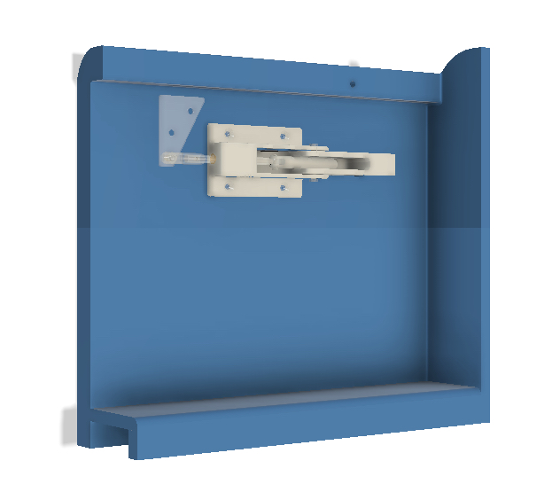
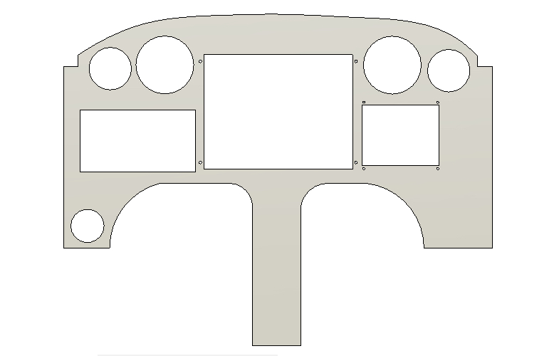
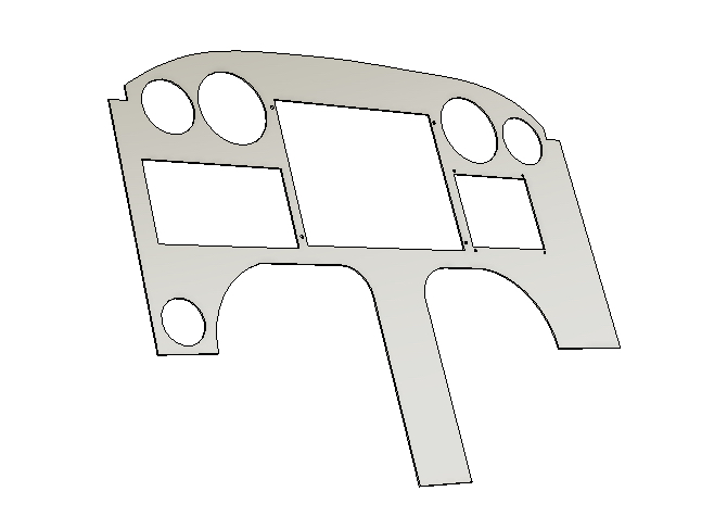
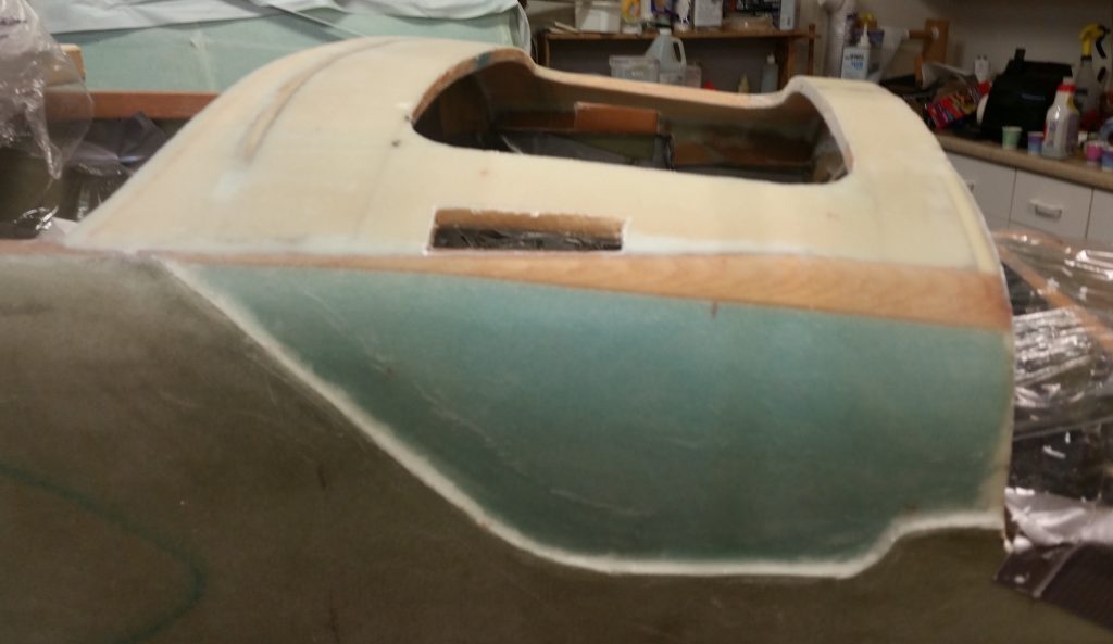
As a reminder of my aft nose cover shenanigans, part of the collective securing of this aft cover includes hinge plates attached to the movable/removable aft nose cover itself that are locked in place to longeron-mounted receiving hinge plates… one on each side of the avionics access opening.  To be clear, this avionics access opening sits just forward of the instrument panel.

Below you can clearly see the near side and barely see the far side opening slit that allows the aft nose cover hinge plates to traverse through the nose structure to lock the aft nose cover into place to the longerons.

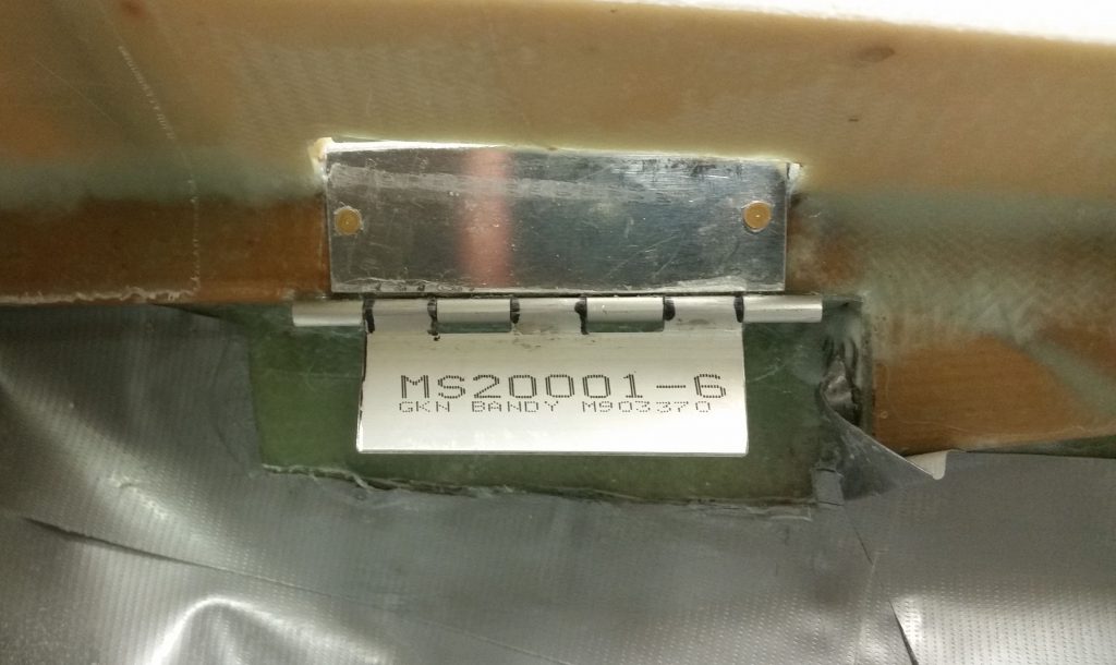
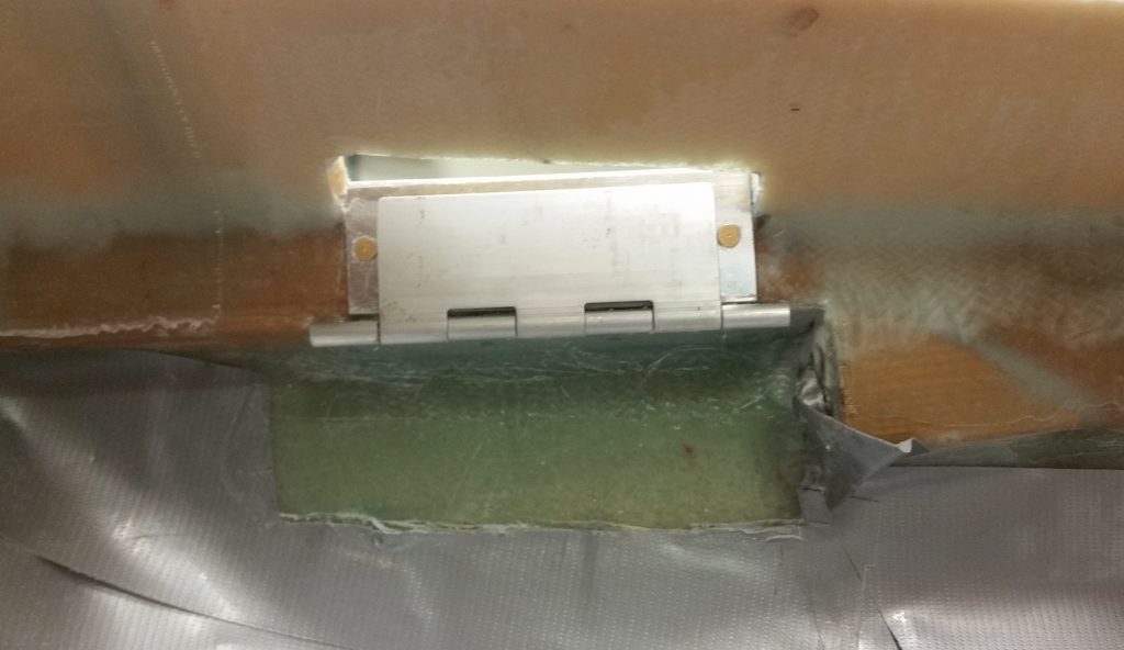
Below is a couple of shots of the mounted hinge plate assembly on the nose/longeron side of the aircraft.  The hinge segment with the part # marking on it gets attached to the aft nose cover which obviously allows for the two hinge segments to interlock together.

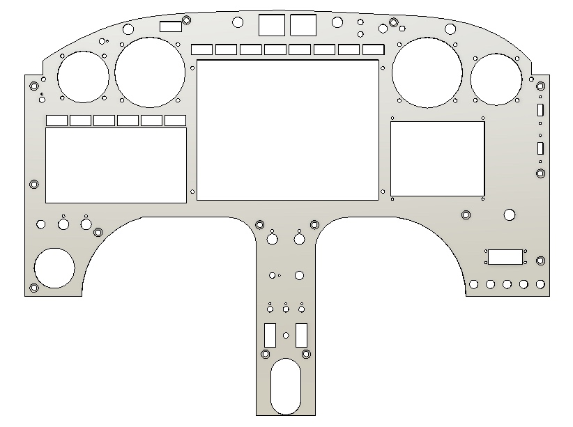
Again, as just one part of a system [that also consists of CAMLOCs and screws] to secure the aft nose cover to the aft nose substructure, these hinge plates are secured to each other via a removable brass hinge pin that replaces the original hinge pin.  This brass hinge pin –one per left & right side– traverses through the instrument panel and is held in place itself by a threaded bung floxed into the instrument panel.

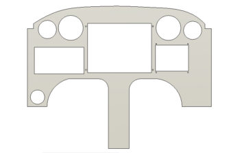
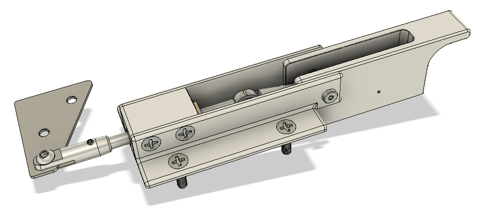
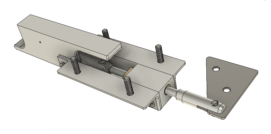
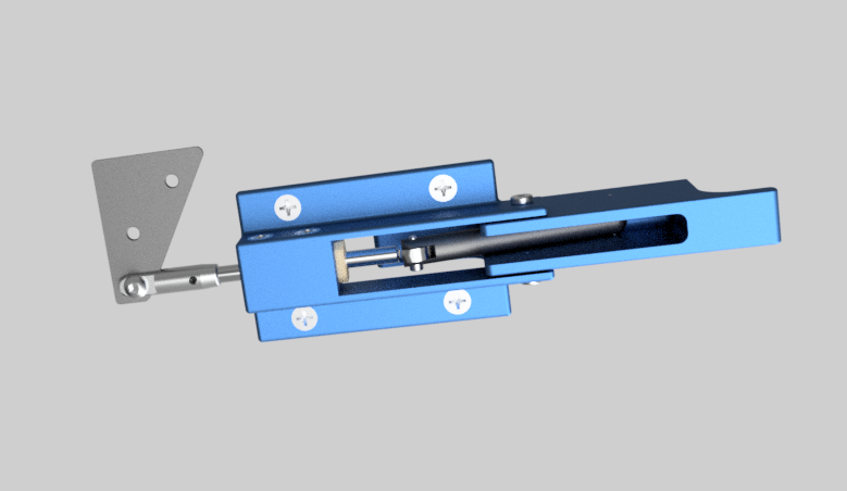
This is my initial CAD-rendered drawing of the aft nose cover hinge pin.

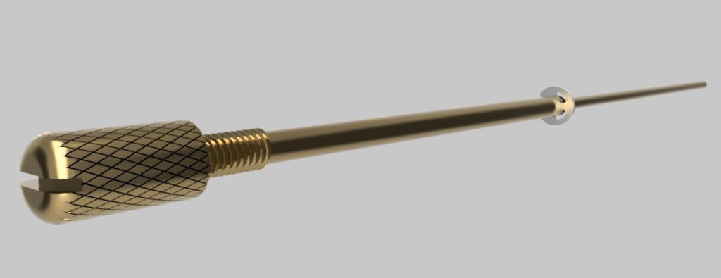
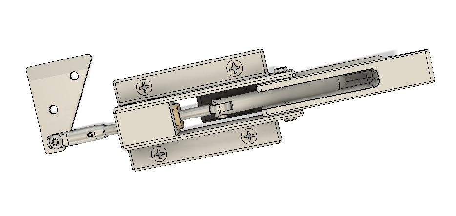
Part of the process to remove the aft nose cover is to unscrew the hinge pin from the instrument panel side and then slide the entire hinge pin assembly aft.  The hinge pin assembly is retained both within the instrument panel and the longeron-side hinge plate (the very aft rung) via an E-style retaining ring (visible in both renderings above & below).

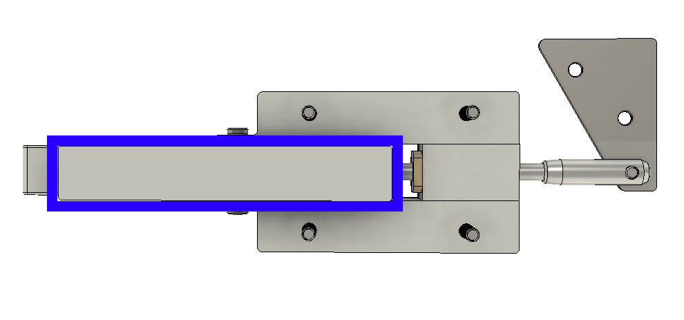
Just forward of the E-style retaining ring (to the right in pic below) the pin tapers down to the diameter required to lock the two hinge plates together (0.089 in.).

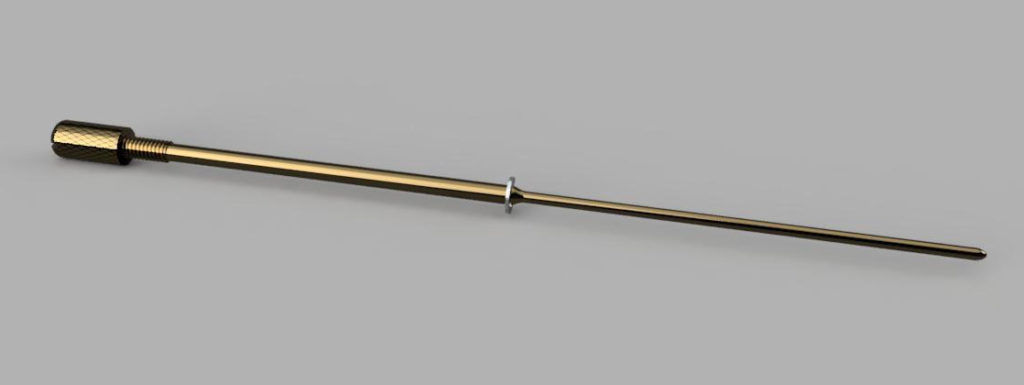
I drew up these hinge pins based off the best information I had available, and again, by using CAD I can fairly easily tweak any of the dimensions if need be.  

Finally, I had planned on making the throttle handle lever my next CAD drawing task, but due to my being sick and then yet another trip to North Carolina, I had to rearrange my drawing jobs.

Chapter 18 – Canopy Latch

Today I was able to create a virtual left-side cockpit space in CAD to get a good feel on the mounting location for my canopy latch.  By adding in a bit of the upper longeron, front panel and left armrest, I was able to just about pinpoint the dimensional specs for installing the canopy latch.

In short, this canopy latch will work as planned to provide me the clearance I need with both the throttle handle and the instrument panel (specifically the GNS-480 GPS).

With a per-plans-spec sized sidewall now in my “possession,” I was able to do a fair number of machinations to also figure out installing a lock for the canopy handle.  Clearly this is, in turn, a lock for the fuselage proper.

I started with a ‘standard’ sized lock but quickly found they were a bit too robust so I went with the “mini” version (1/4″ less in diameter), which seemed to both fit and look better.  

Although in rough format, this pic provides an idea of how the external side of the canopy latch handle will look . . . along with the lock.

I’ll continue to do some research and brainstorm ideas up until the point I actually make the canopy latch.

In other news, as a sideline process from analyzing the instrument panel as I drew it up in CAD, I spent about 30 min on repositioning the switch functions of the Video Camera reverse/forward toggle controls –from having their own standalone switch– to the throttle handle 5-way castle switch.

I then spent nearly an hour creating the Lathe CNC Conversion electrical diagrams.

Chapter 22 – Panel in CAD

Continuing on with my CAD blitz as I wait out the final stages of being sick, as I noted in my last blog post I undertook a significant item on my to-draw list: the Instrument Panel.

This has been a multi-day endeavor that in many regards is just a best-guess attempt at getting the numbers right since [again] I don’t have the panel mockup in hand.  Moreover, I based the major panel dimensions off of the cardboard mockup that I made up in 2012 and used extensively while both in Tampa, FL and Qatar as I assessed various panel components/configurations.

Not a big deal of course since it’s EZ-PZ to move components around on the panel in CAD. The bigger deal is getting the component holes sketched onto the panel in the first place.  To take the drama up even another notch: the biggest deal is the painstaking detail of ensuring all the components are aligned correctly with their mounting holes and the myriad of required clearances —just enough with this tight space— with each other.

In all likelihood –considering all the major avionics are currently dialed in with each other– the most significant changes from here on out will be on the order of moving the entire avionics section a tick left or right, and a smidge up or down.  Switch locations and spacing, as well as entire rows of switches, will be highly subject to tweaking as well.

That all being said, here’s another bit fancier version that I rendered up. 

Next up in this CAD drawing series will be my unique throttle handle lever.

Chapter 18/22 – CAD Attack!

As has been evident many times before in this build, there is often layer upon layer of interdependencies that drive design changes (aka “mods”).  This very point became evident after I received my GNS-480 —and after I placed it in just about the only place it could go in my panel— when I realized that my EZ Rotary Canopy Latch from Jack Wilhelmson was just not going to fit.  And believe me, for the price I paid and the beauty and quality of Jack’s latch, it was not something I chucked aside in a momentary flight of fancy for something else!

At the time I remembered that both Bill Allen and Mike Bowden had rather unusual canopy latches, somewhat similar in style and appearance, and both of which I had seen at the Rough River fly-ins.

Well, through Alaska Long-EZ builder, Brian Ashton, I was linked up with Mike Bowden… who graciously gave me a very thorough run-down of the dimensions on his canopy latch. These conversations took place almost a year ago.  

Well, today I finally got around to plugging in all the known dimensions and extrapolating a few of the others to draw up Mike’s canopy latch in CAD.  The one significant mod I made is that I added a triangular pivot plate to the canopy latch arm which will allow a forward reaching pivot arm to manipulate the forward canopy hook.  If you’ve seen Mike’s Long-EZ than you know he has no need for one of these since he has a permanently attached windscreen portion on his canopy (like an F-104 Starfighter).

The shot above is a somewhat straight-on view of what you’d see in the cockpit.  The one below would be an upward view of the latch from the pilot seat area.

This is an outboard view of the canopy latch, shown with the 4 mounting screws that will secure it in place on the fuselage sidewall.

Here’s another outboard view, but here I’ve highlighted (blue rectangle) the exterior handle part of the canopy latch that will be visible from outside the aircraft.

And a snazzed up version of the canopy latch.  As I’ve mentioned over the past few weeks, I plan to machine the majority of these CAD-drawn components using CNC once I get down to North Carolina and settled in.  That being said, I should also note that I’ve been quite sick this week, so I’ve been doing some CAD work to pass the time (when I haven’t been passed out!).

With the canopy latch design and CAD drawing pretty much finalized, I then set my sights on the Instrument Panel.  I don’t have the exact dimensions on-hand since my project is down south, but I can always easily tweak those numbers later.  In addition, I simply started out by placing and “cutting out” the holes for the major panel avionics and instruments.  As time goes on I’ll tweak this drawing to account for switches, circuit breakers, etc.

Besides, a little birdie told me that if our schedules sync up that I may just be able to get this panel plasma cut (vs CNC’ing it), which would save quite a bit of time (wink, wink)!

Tooling Up: Power Drawbar

I’m pretty much done with the design of my Milling Machine’s Pneumatic Power Drawbar. For a better understanding of what a power drawbar does exactly –all related to tool changes– I’ve provided a link to Marco’s video on his power drawbar.

I’ve been feeling under the weather the past few days, so I got lazy and simply took some screenshots of my CAD-assembled pneumatic power drawbar right off the computer screen with my phone.

This shot shows the lever and cam function with the air cylinder, lever arms and rear pivot pin.

My version will have the drawbar actuator button on a front face panel. 

I then rendered the CAD-assembled power drawbar, adding a splash of color.  Again, this shot shows the internal lever arms, etc.

While this view shows the front face attached with the actuating button in place.

For an animated version of the rendered drawbar, showing different view angles (not any component movement…), click here.

Tooling Up: CNC Update

Having just returned from my North Carolina “hangar” trip, and needing a couple of days R&R from multiple trailer loadouts from my storage units to my hangar, I decided to focus on my upcoming machining CNC conversions before dropping them like a hot potato as I begin my renewed focus on instrument flight training and prepping my house for sale.

Below are the major components, both in material and components, that I’ll need to construct a power drawbar for my milling machine (side & top plates; pneumatic cylinder, air valve and switch; Belleville washers; steel stock for new drawbar, etc.).  This will allow me –with just a touch of a button– to quickly swap out the milling tools during a CNC operation.  Quite a handy capability to have since it allows tool changes within literally seconds versus having to swap out a tool manually… which on a milling machine requires 3 hands and is much more laborious than swapping out bits on your standard drill press. Also, there is more raw material and other bits coming soon for the power drawbar “kit” that I will include in an upcoming order to Aircraft Spruce.

Here’s a quick update on my lathe CNC conversion project as well.  Although converting the milling machine to CNC is the priority, I am slowing collecting bits ‘n pieces for the lathe CNC conversion.  As you can see below, I have the housing for the lathe CNC system (a converted tool box ala YouTube ‘CNC guru’ Franco); Z-axis closed-loop stepper motor, drive, power supply; Emergency stop switch & cable; copious amounts of hardware; aluminum stock; CNC touchscreen laptop that meets Acorn’s stringent specs; and a control pendant (XBox controller) with buttons/joysticks remapped to drive the Acorn CNC12 software.

And a more head-on view . . . additional hardware is on order, and as with the drawbar above I will be ordering some raw aluminum stock from Aircraft Spruce.  The Z-axis motor shown is a 3 Nm (425 oz/in) Nema 23 and I’ll pick up a 2.2 Nm (310 oz/in) for the X axis.

Here’s a screenshot –although not exactly as I have mine– of the XBox controller’s buttons and joysticks reassignment through the reWASD app.  After downloading reWASD & hooking up my XBox controller to my laptop via USB, I was then able to remap my XBox controller to use assigned keystrokes as I would if controlling the Acorn CNC12 software with the computer’s keyboard.  Moreover, on the reWASD site there are 3 preprogrammed Acorn CNC configuration profiles that you can download and use to be quickly up & running.  I downloaded Rick Sparber’s configuration (below) but then tweaked it a bit more to my personal liking.  I’m sure as I actually use it more tweaks will ensue.

Next, here’s a shot of the Milling Machine’s massive 8.5 Nm (1200 oz/in) Nema 34 Z-Axis closed loop stepper motor and cables, along with its HBS860H motor drive.  MIA here is the 60V unregulated power supply which is on backorder.  In addition, the X-Axis 4.5Nm (637 oz/in) Nema 34 closed loop stepper motor, drive and power supply is on order and in transit.  This leaves just the Y-Axis motor left to buy.  Also, I placed the 9V battery in the pic simply for size reference.

Finally, I did a power ops test of the Centroid Acorn CNC Board and power supply before then doing an Acorn CNC12 milling software Bench Test after getting the CNC laptop (CNCPC) to communicate with the Acorn board.  Part of the Bench Test is of course getting a good software install on the computer.  With a good Bench Test under my belt, I can now move onto the next step of connecting motors (which will be a bit down the road).

The only glitch I had is that during the initial connection between the Acorn CNC board and the CNC12 software I got a message notification onscreen to cycle the Acorn Board’s power.  However, literally everything I’ve read and every video I’ve watched all strongly warn that power should not be removed from the Acorn CNC board during initial connection with the computer.  I did some quick research, then as a safety measure I powered down the laptop before cycling power on the Acorn board.  It worked out fine and I was then able to proceed with the CNC12 software load, initialization and Bench Test.

Besides a future pic or two of some components, this will most likely be my last discussion for a while on my machining CNC conversion endeavors.  I’m sure a lot of you experimental purists may feel relieved by that, wanting to simply see more of mainstream airplane building . . . so I’ll leave it at that! 

Hangar? Yes please!

Although I had been “forewarned” that the call was imminent, I received it while in Portland helping out my Mom: I was officially being offered a hangar at Michael J. Smith airport in Beaufort, NC.  

Now, I had actually been offered my pick of 2 different hangars at the end of December last year (2018) but decided to wait knowing that I couldn’t do anything with a hangar at that time due to my holiday travel schedule.  I opted to wait for what was stated as just a couple more hangars that would come available sometime in January.  Well, the “couple of hangars” turned out to be my pick of 4 hangars.  

It may seem a bit early in my project to snag a hangar at this point, but a couple of extenuating circumstances helped finalized my decision for me:
1) The reason behind all these hangars coming available was due to the construction of 10 new hangars on the airport with many airplane owners vacating the older hangars in an exodus to the new hangars.  Bottom line, this was a one-time opportunity for the very foreseeable future.
2) I currently have 3 storage units to hold all my stuff, including my Long-EZ project. Due to the configuration of the storage unit containing my Long-EZ fuselage, it makes it difficult to use all the space available since I have to provide clearance around and above the fuselage.  My goal is to transfer all the Long-EZ project related components and all my tools to the hangar from storage units #2 and #3, and then transfer the remaining stuff from storage unit #3 to #2.  With storage unit #3 empty I’ll then rid myself of one storage unit, and apply that saved monthly payment to the hangar.  For just a bit more money a month I’m calling this a Win-Win.

Since I got first pick of the 4 available hangars, I chose a south-facing hangar that provided both more natural sunlight and a longer “driveway” (see pic below) that will allow me to haul the plane outside and work on it if need be.  Best yet, since the hangar I chose is an end unit, I have the corner area –that would normally be part of an opposite-side “T” hangar– available to me.  Clearly much more space [about 120 sq. ft more] for just a bit more a month.

So due to uncooperative bad weather forecasted for next week, I had to pull the trigger quickly within just a couple days of returning from Portland, OR.  I rented the venerable fuselage-hauling trailer, spent a day loading it up with my two bigger external sheds from my VA house, and then headed down to North Carolina.

Above is shot of the loaded trailer after the first big reveal of my hangar…. opened by me for the first time.

Below is a shot after I unloaded the smaller shed off the trailer and the wood framed base of the larger shed (out of site).  The harsh shadow makes it hard to see, but you can get a general idea of the more than adequate space available for a Long-EZ.

Again, the south-facing hangars have a much longer “driveway” off the center taxiway than do the north-facing hangars.  This provides plenty of clearance to pull the airplane out quite a ways if need be to work on it.

Of course I chose this airport not only since it has 3 longer Long-EZ friendly runways, but the area around it has a lot of beautiful scenic water: ocean, rivers, waterways and bays. From my hangar I can look over and see the new high bridge (to allow sailboats to pass underneath) between Morehead City and Beaufort.

Below is another shot of the hangar.

Another shot of the hangar with my trailer empty and ready to haul the fuselage!

After I dumped my initial load from Virginia, I then went to the storage unit and once again loaded up my Long-EZ fuselage, the left wing, and my motorcycle to haul them to the hangar.  You can tell by the long shadows that this was earlier in the morning, and on a cooler winter’s day heat wasn’t a factor during the 30 min trip between storage unit and hangar. 

I tried a few times to snap a shot showing the inside of the hangar and still have enough light to see everything inside.  Below was the best shot I could get… not the best but still provides enough to show how the fuselage is dwarfed by the size of the hangar.  Definitely much more space than my 2-car garage shop provided!

This was round one of moving from the storage unit to the hangar.  Round 2 will come Monday where I’ll try to get the remaining tools and Long-EZ stuff over to the hangar and clear out storage unit #3.