
Not that I am… but I like the concept!
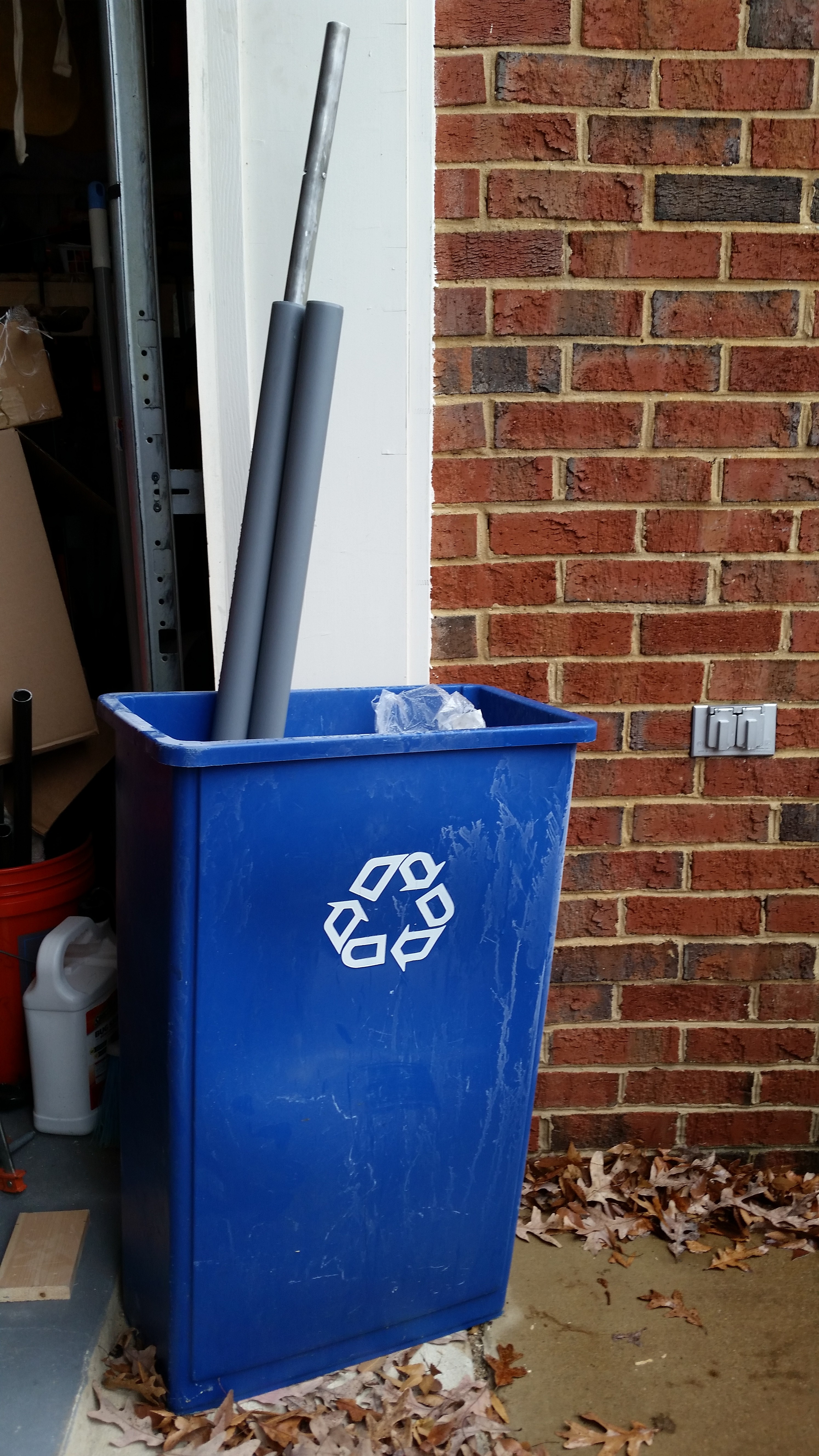
I started off today by sanding down the left elevator tube and then Alodining it. It was raining lightly so I let the tube soak in the PVC pipes just inside the garage door & out of the rain. As you can see, to keep the tubes upright I simply stuffed them into my shop recycle bin.
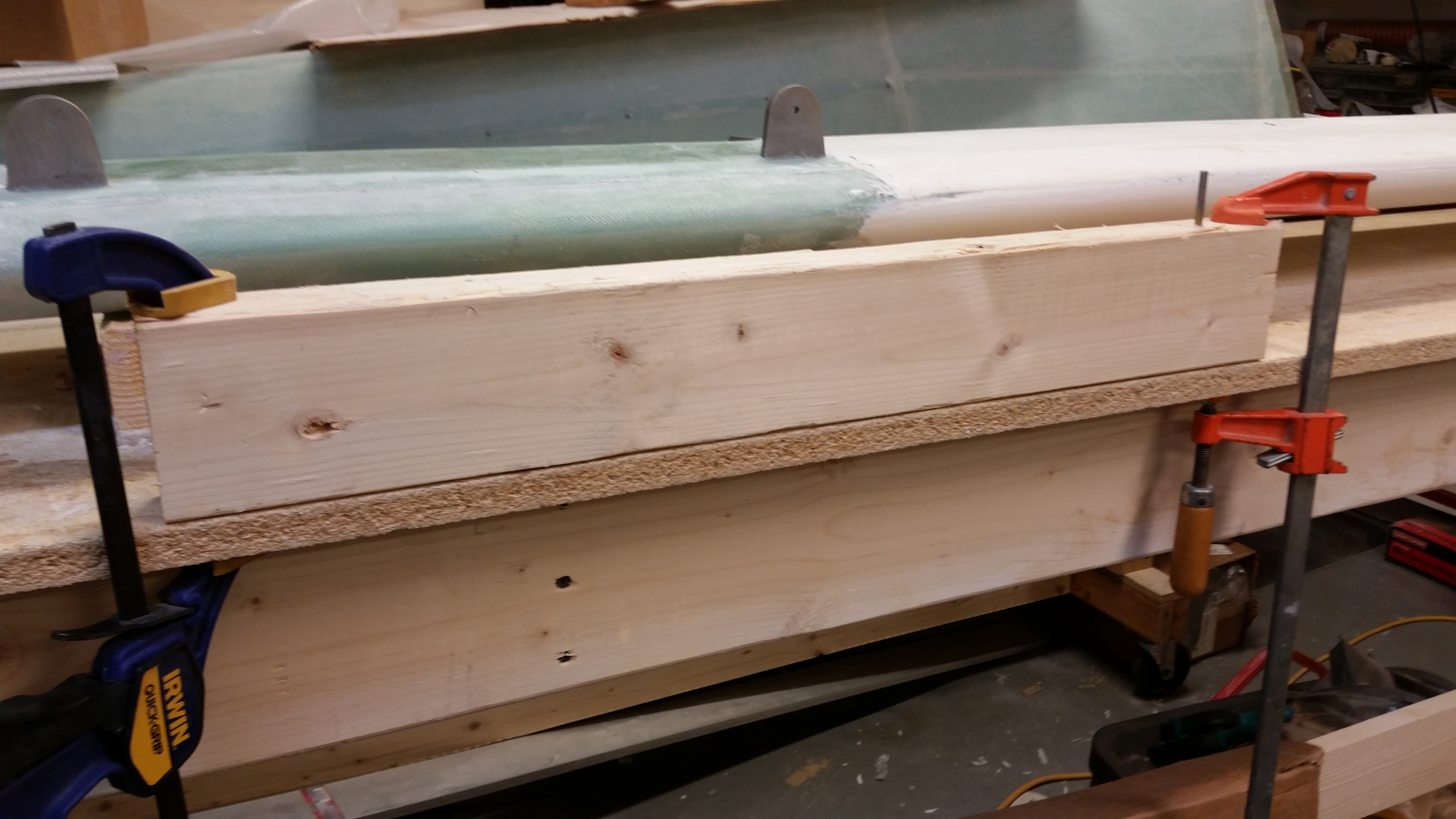
In between the extended soaking times of my very weak Alumaprep & Alodine, I measured out the fuselage “saddles” that will keep the fuselage safely atop the fuselage dolly.
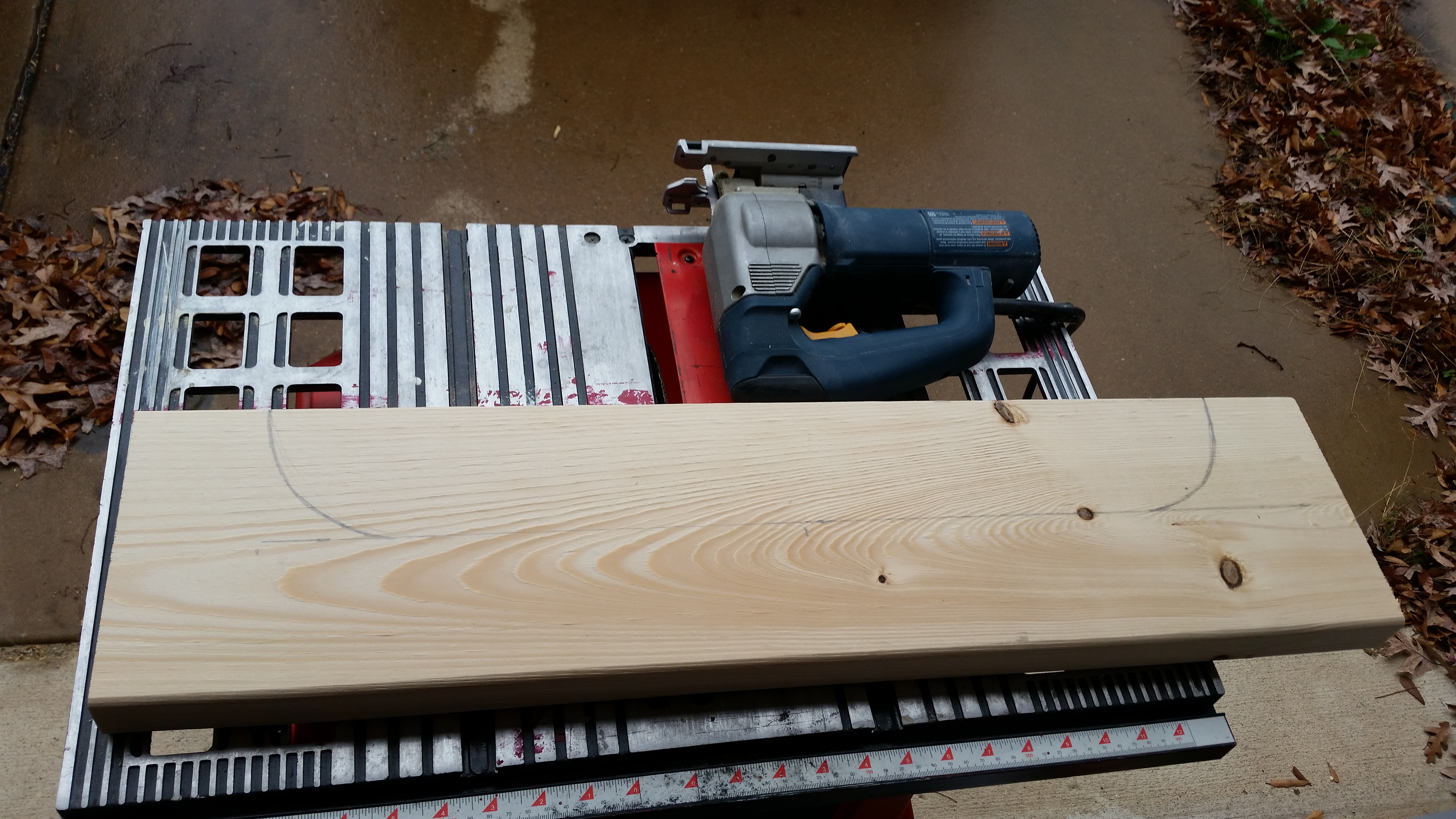
I kept the bottom of each saddle 3-1/2″ high to keep them the same height as a regular 2×4.

Here’s the first cut “saddle”.

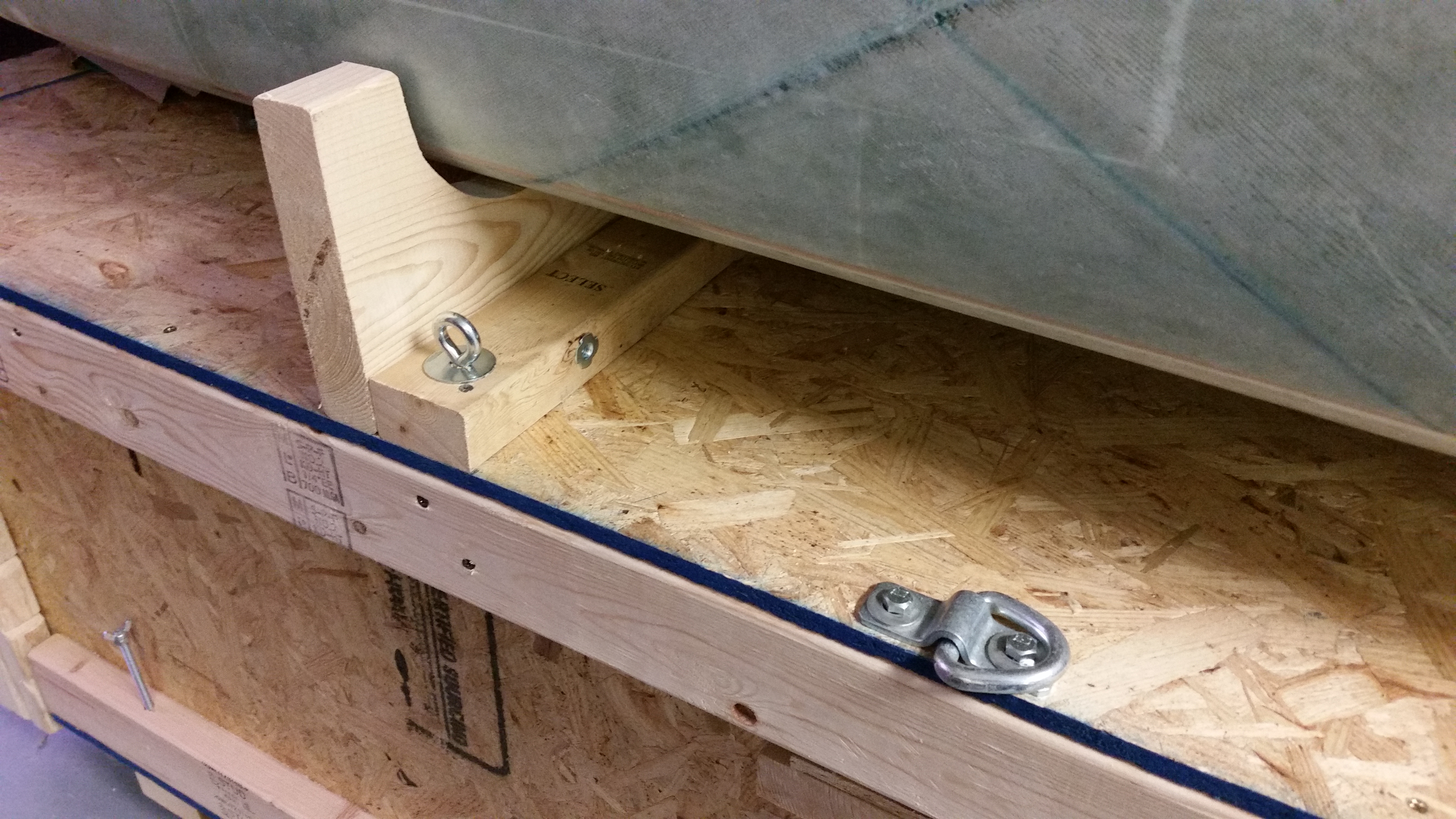
And here are the saddles in place, although not yet mounted.
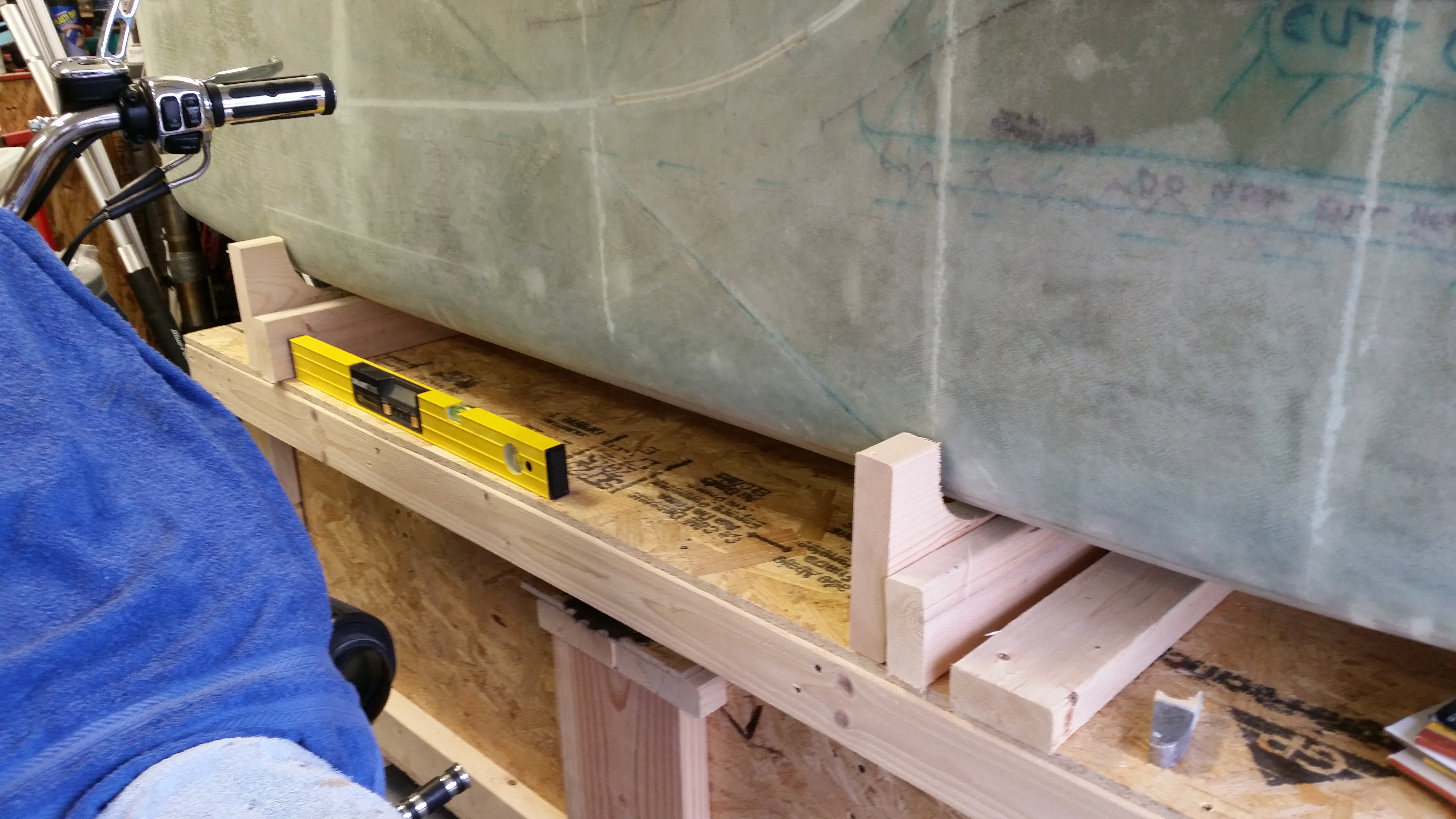
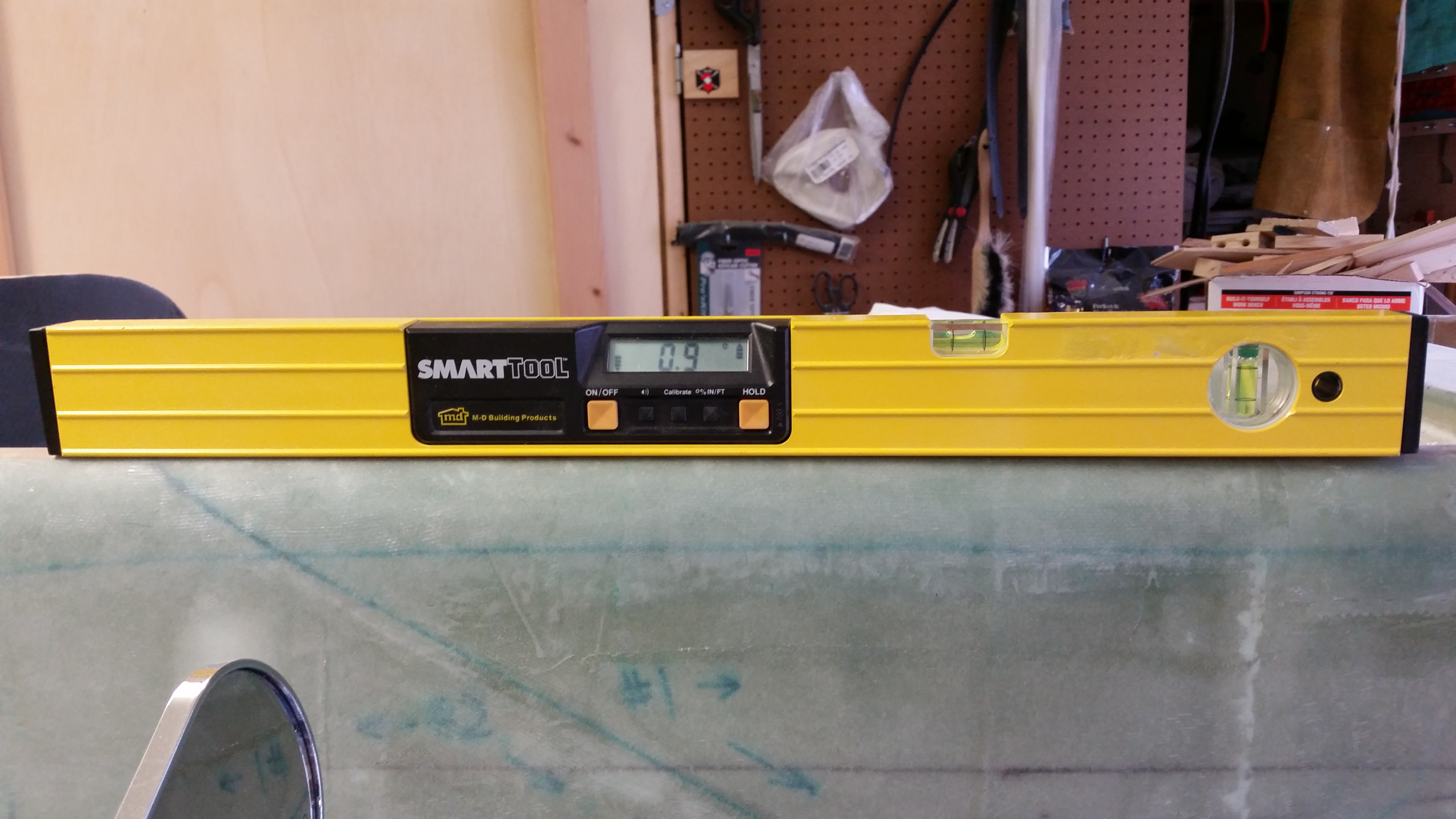
I should note that before I cut the front saddle I measured the angle of the work top of the fuselage dolly.
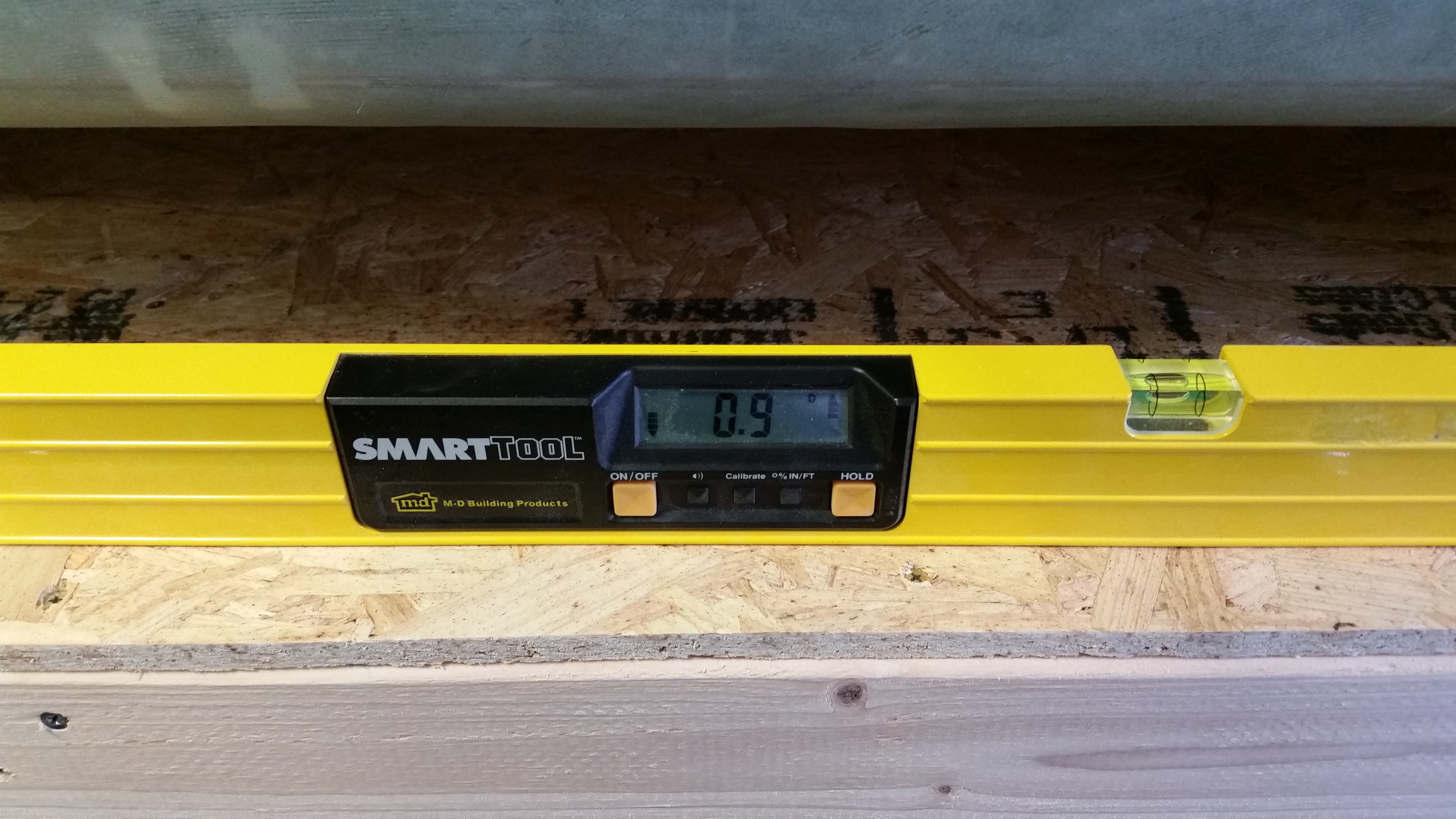
The goal to match the angle of the longerons with that of the work platform on the fuselage dolly. As you can see, they both came out at the same angle.
My next task was to drill a 3/8″ hole 4 inches from the side of each saddle into the 2×3 below it. The 2×3’s will be mounted flat and then each saddle bolted to the 2×3.

Here’s a shot of the fuselage mounted on the fuselage dolly in the saddles.

I also mounted 3 tie-down points on each side of the fuselage dolly: one next to each saddle, front & aft, and then one in the middle of the work table.
Along with finishing up a lot of tasks on the fuselage dolly, I also reorganized the garage to facilitate the nose build and cleaned up a bunch. After I finished with my non-build tasks, I got back to work on the left elevator rebuild.
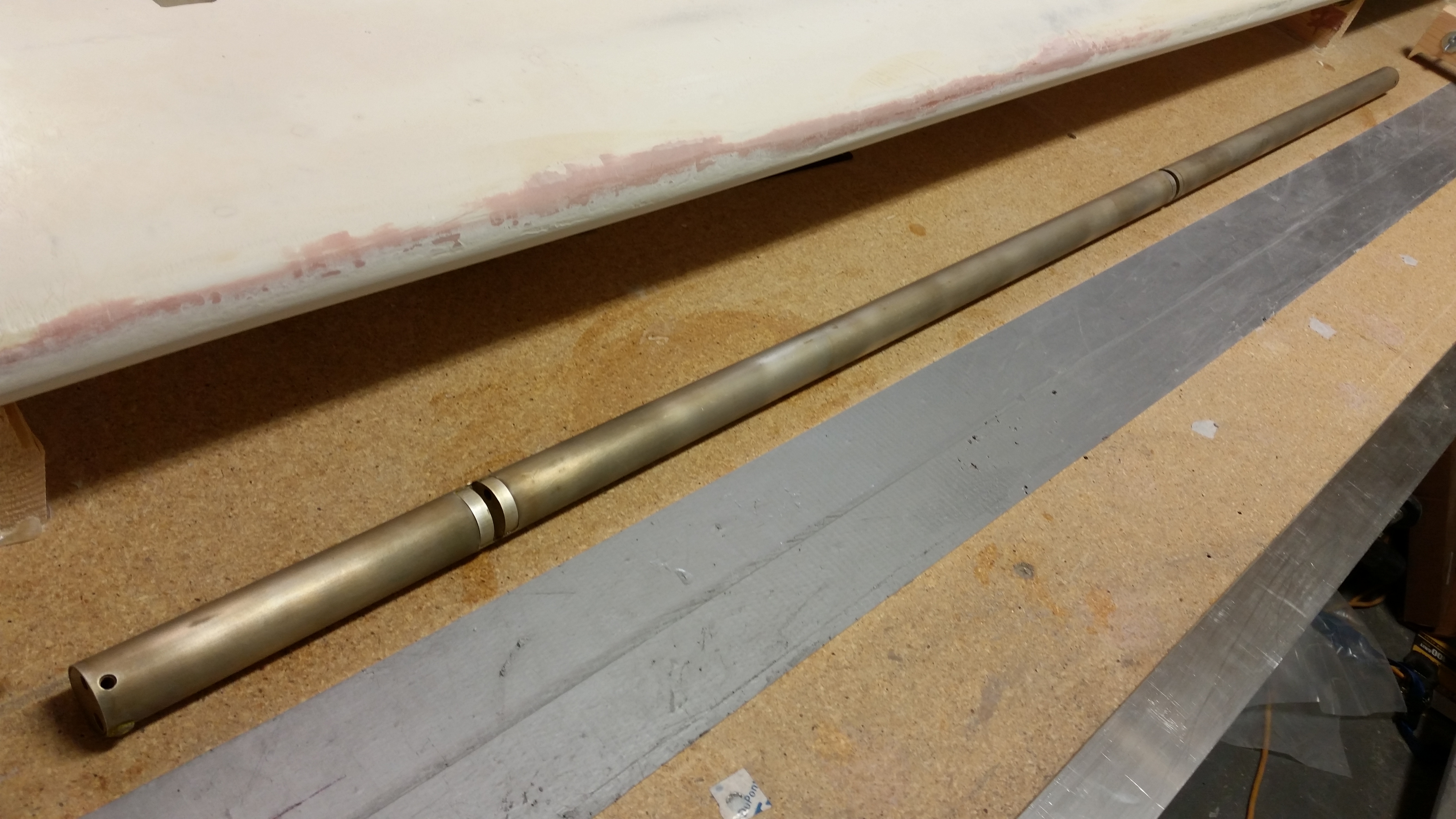
Below is a shot of the elevator tube after the Alodine dried.
Now, to get the left elevator foam core mounted on the elevator tube so that it matches the right elevator tube, especially the TE, I simply couldn’t build it as if it were a new build. Why? Well, when I originally drilled the elevator tubes to mount them to the torque offsets, which occurred at the same time with both elevators aligned, that action locked in the two elevators so that they were in synch and also ensured that the TE’s matched in trail.
Thus, I had to do a little reverse engineering in mounting the left elevator foam core to the left elevator tube. I had been pondering this quite a bit over the last week and finally decided to mount the elevator foam core with the elevator tube mounted on the canard, in conjunction with the other elevator tube, spool tube, torque offsets, etc. exactly as it would be in its final install. In using this method the first step would be to lock the right elevator TE in place, and then that would let me know where the left elevator TE needs to be.
Now, to take this one step further I wanted to mount the elevators to the canard with the canard in a nose down/TE up position. I pondered on this a bit as well and finally decided on a method:
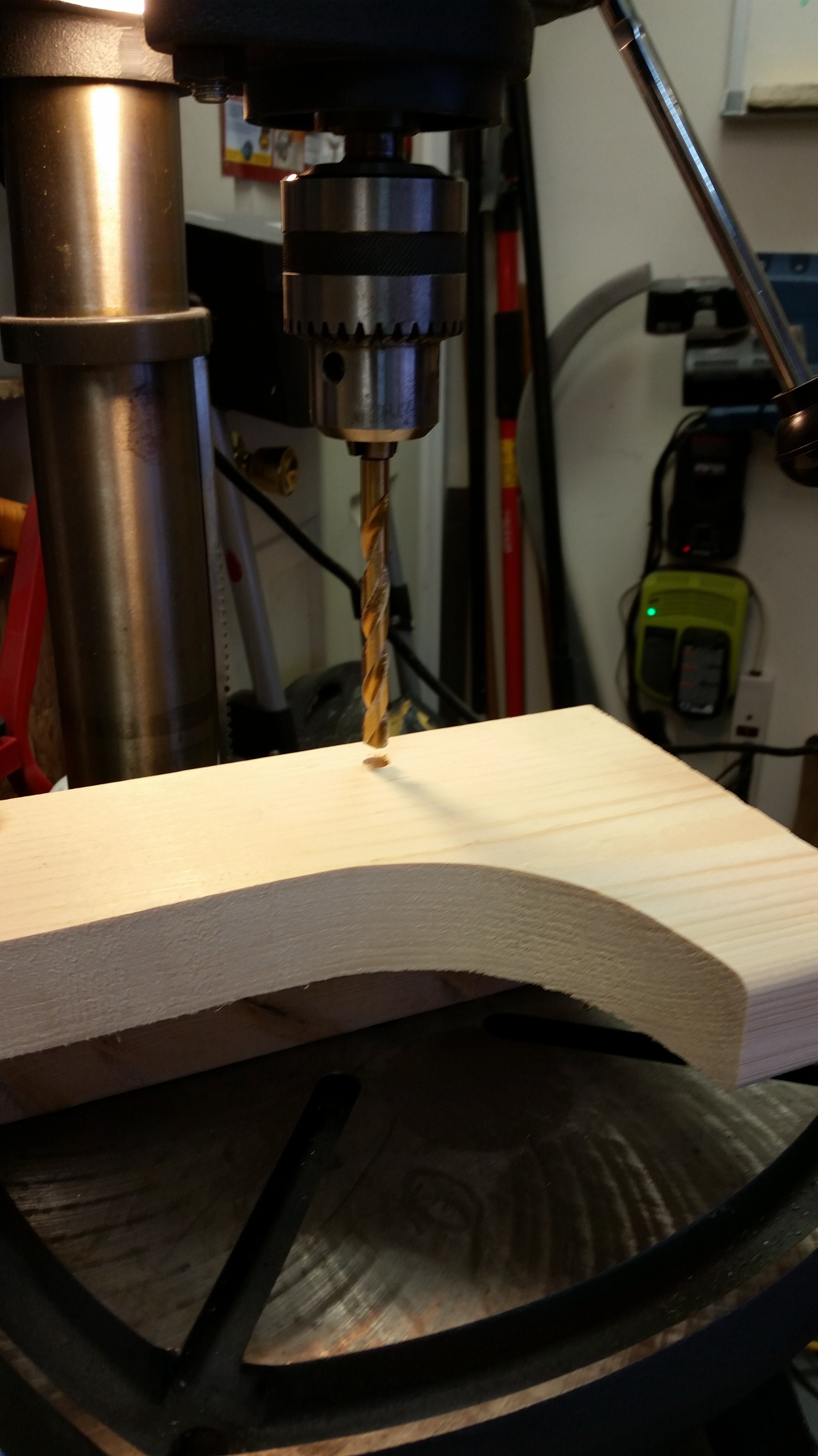
I started by measuring the distance between the LE and the canard mounting tabs, which was about 3-1/2″… obviously the same width as a 2×4. So I mounted a 2×4 to the work bench with clamps. I really wanted to avoid (at worst minimize) any damage to the mounting tab holes, so I used a drill bit as a smooth mounting peg on one side by simply drilling the bit into the 2×4 until the cutting edge disappeared into the wood. I then released the chuck and left the drill bit in the 2×4 (you can see this drill bit on the top right side of the 2×4).
Here’s a closeup shot of the drill bit as a mounting peg.
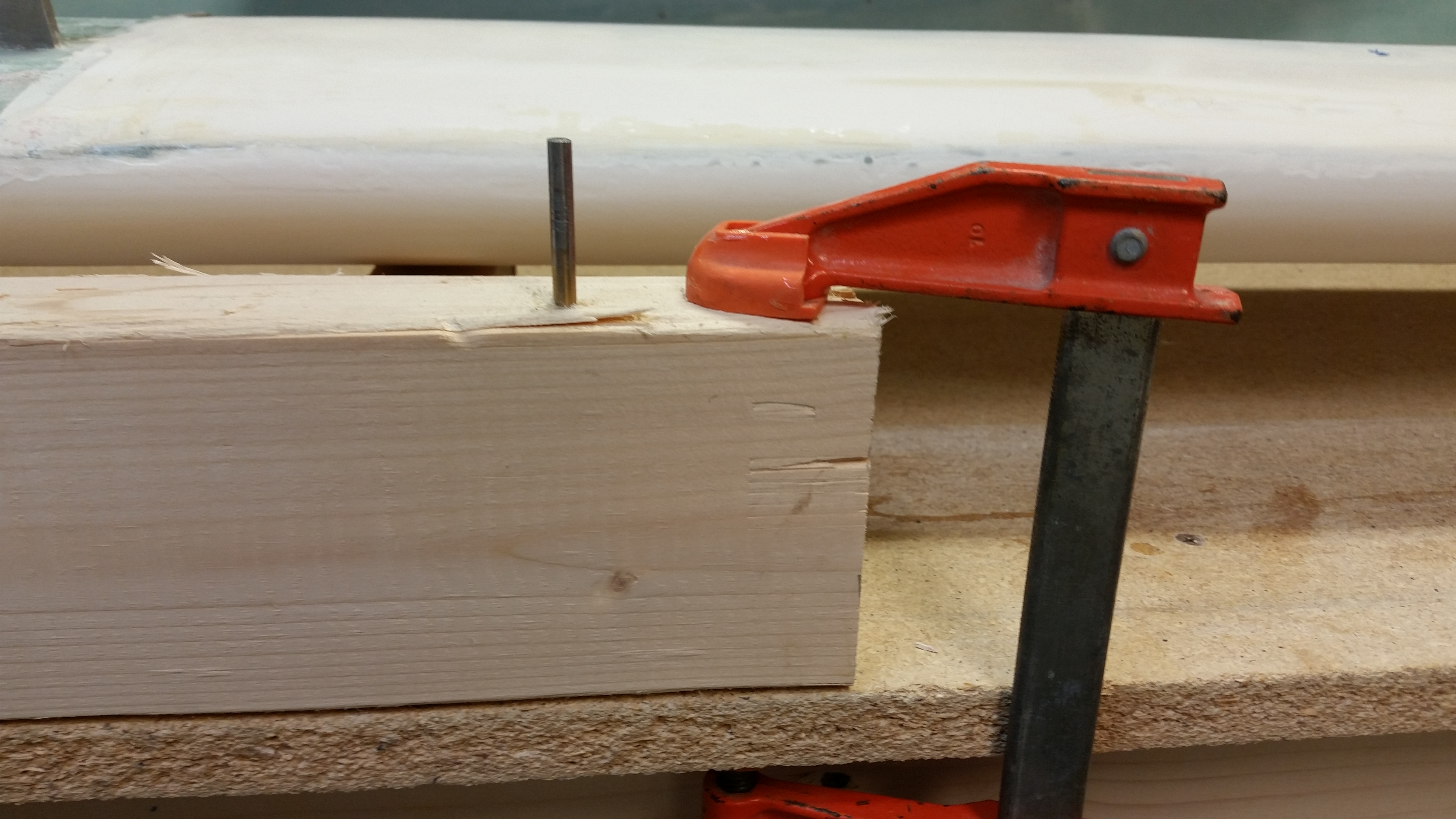
I then used a fine-threaded screw and covered all but the first 25% of the screw threads with electrical tape to mount the other canard mounting tab.
The first issue I noted is the mismatch between the TE of the new right elevator and the TE of the right swoosh tip. Now, I haven’t done specific measurements on the width of the of the elevator, so this may be a passing issue. Of course I made a note of it and it will have to be remedied in some fashion.

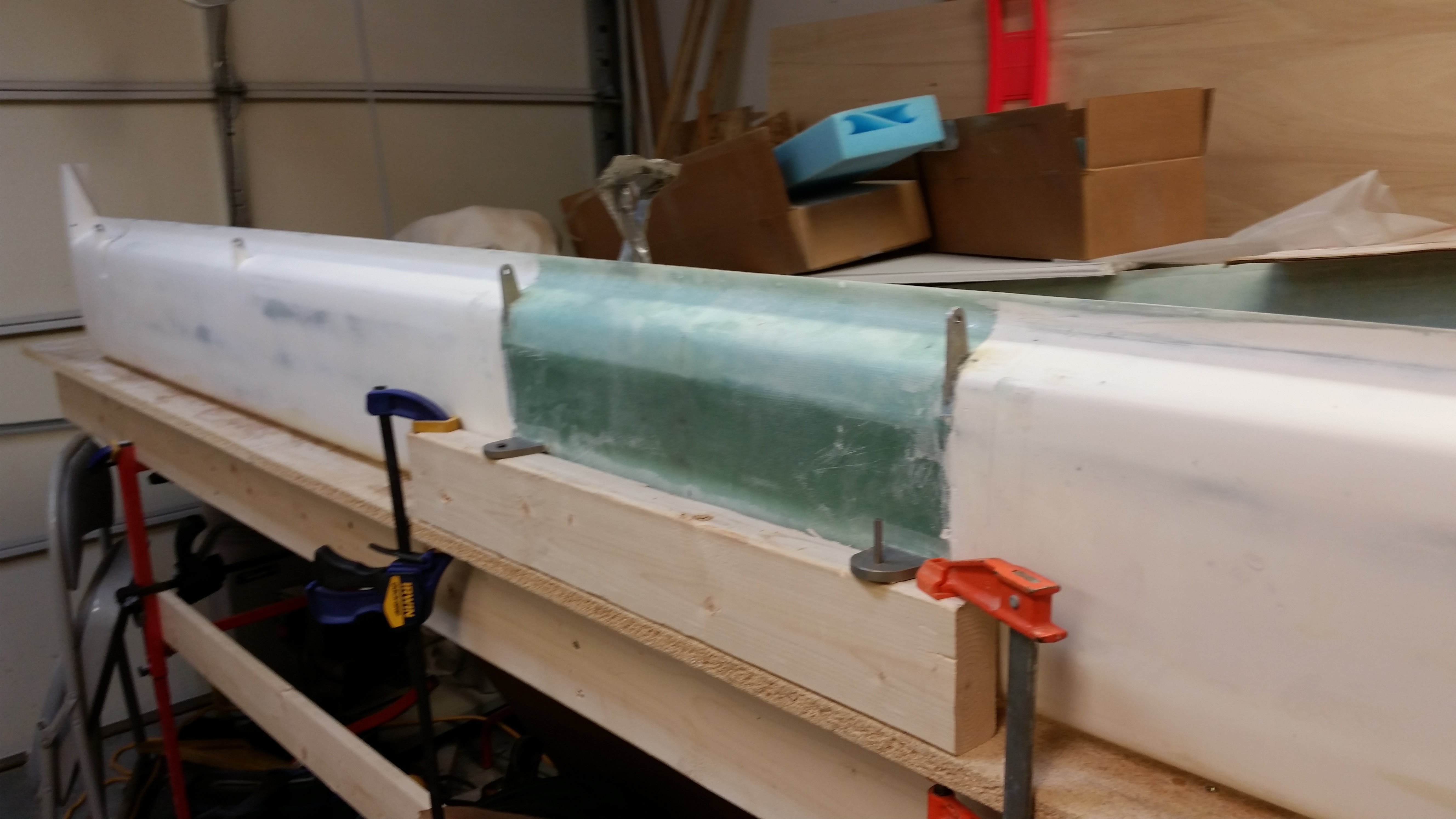
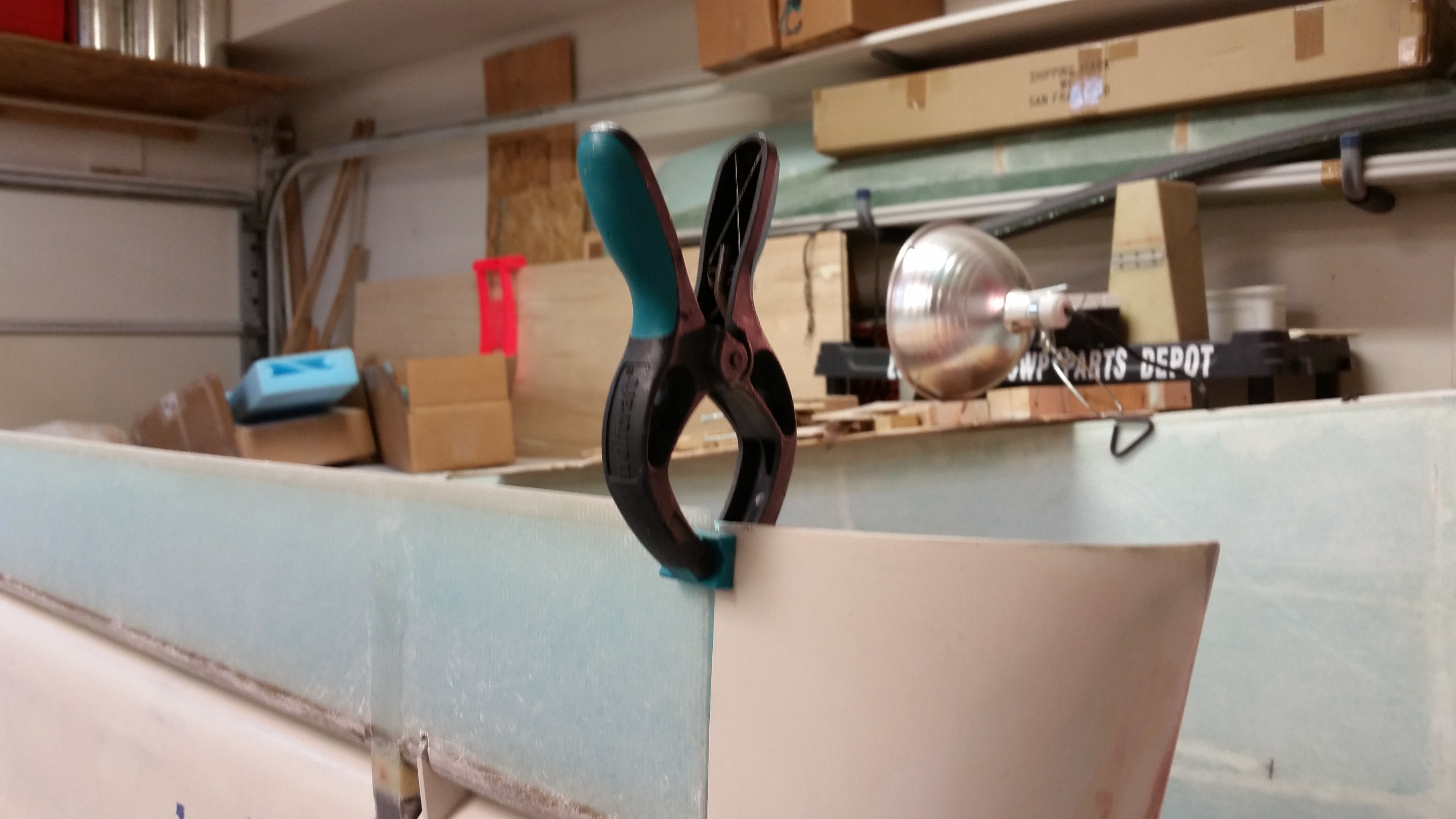
I then clamped the right elevator TE to keep it aligned.
Since this evening was all about fixing my elevator woes, it was nice to finally have something go right, as in I’m very happy that the outboard elevator weight fits perfectly into its notched home in the canard.

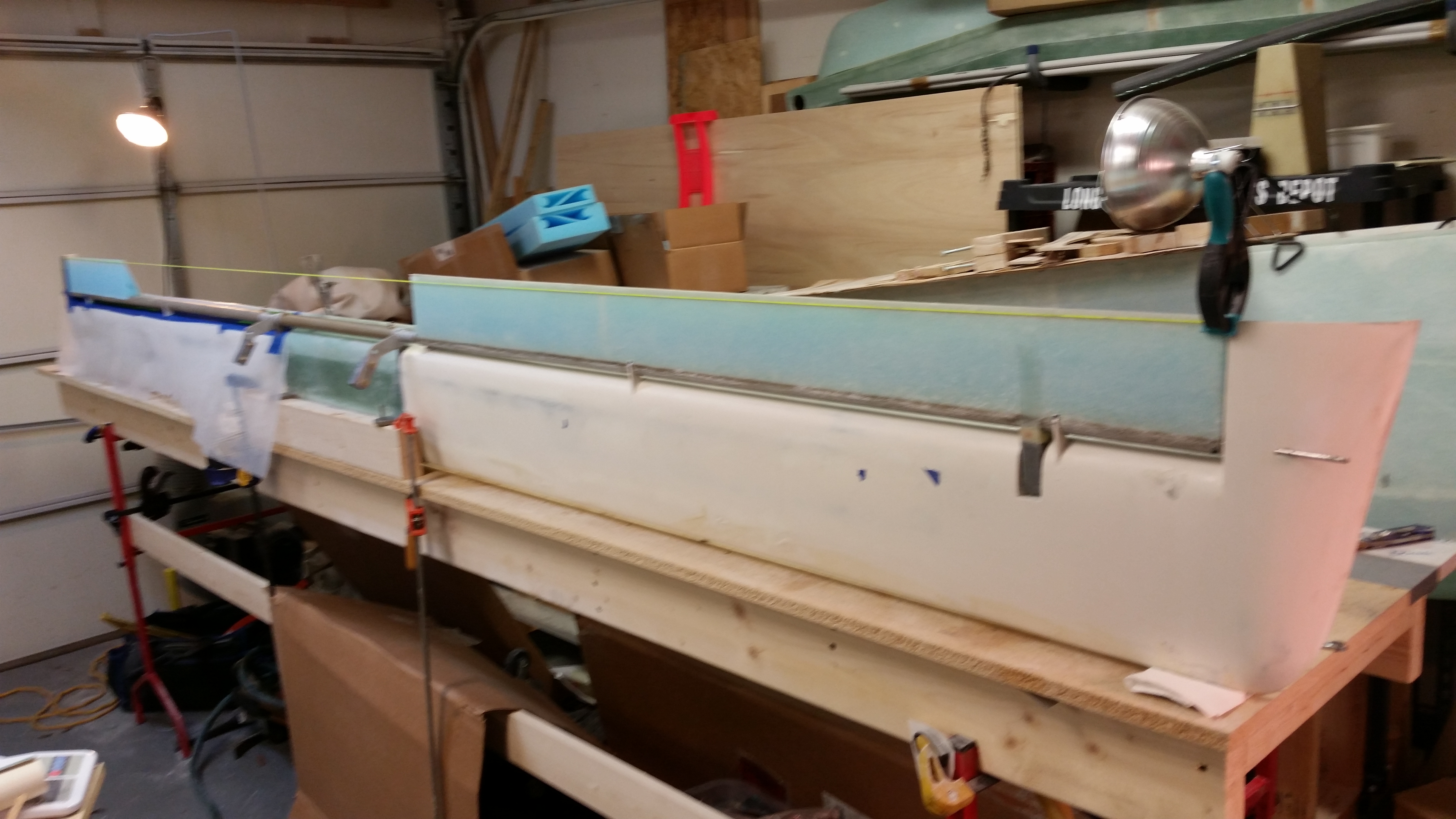
Here’ are couple shots of the canard with right elevator, et al, mounted.
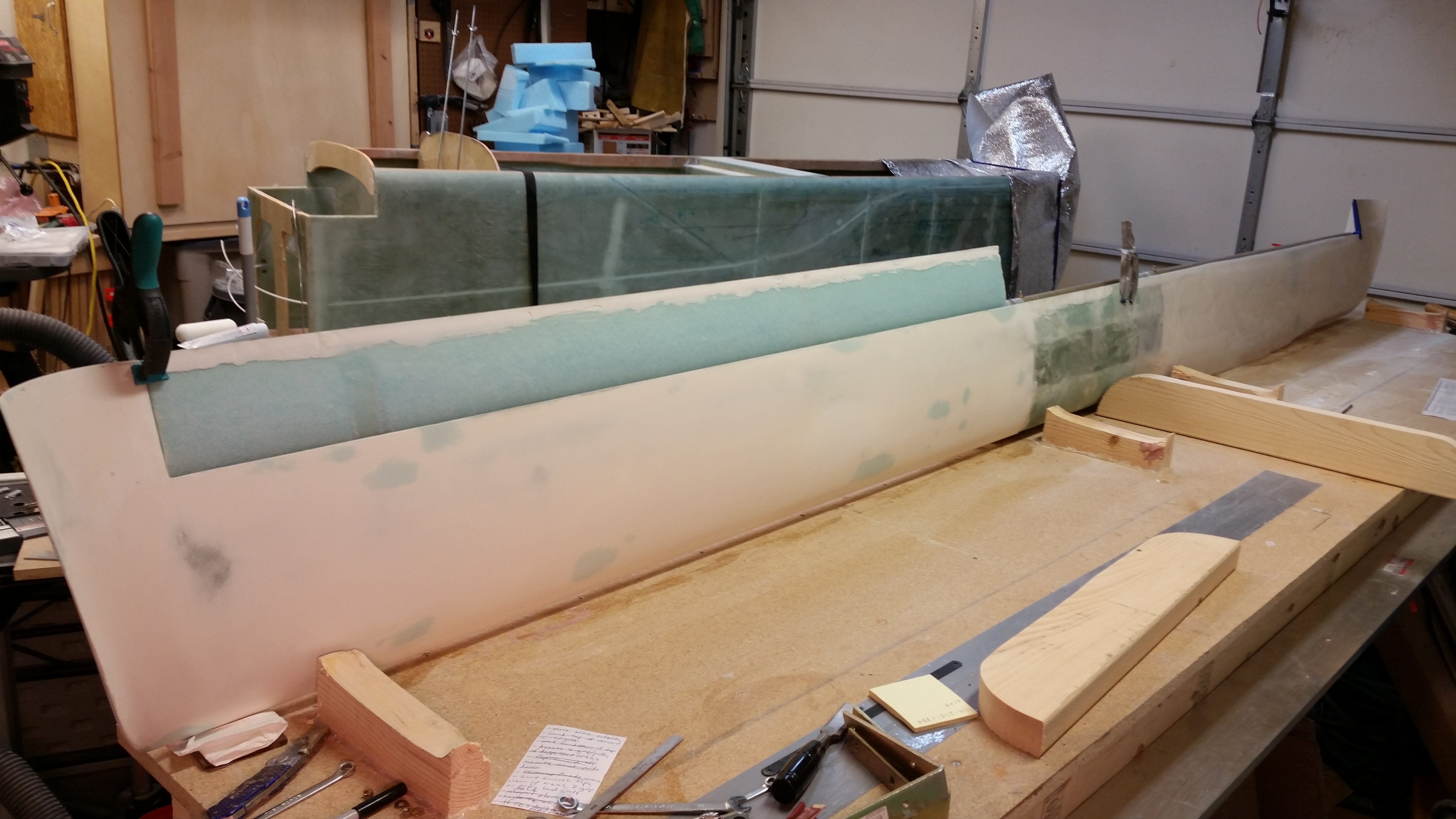
Now, I have to admit that I just could not get either of the hinge pins into the inboard tube hinge points. I finally unmounted the canard, laid it flat in its normal right-side-up position and with a little firm coaxing and twisting with vice grips those suckers slid right in. On the bright side I guess it’s nice to know that they’ll go in when the plane is right side up. It would suck if it was the other way around! Yuk, yuk!

I then pulled out the second set of elevator foam cores that I just recently got from Eureka CNC.

To check how square the ends of these foam cores were I placed them end to end.

I then measured the paired cores and marked a line at 53″. I then cut the second foam core and confirmed that the two combined cores equalled 53″.

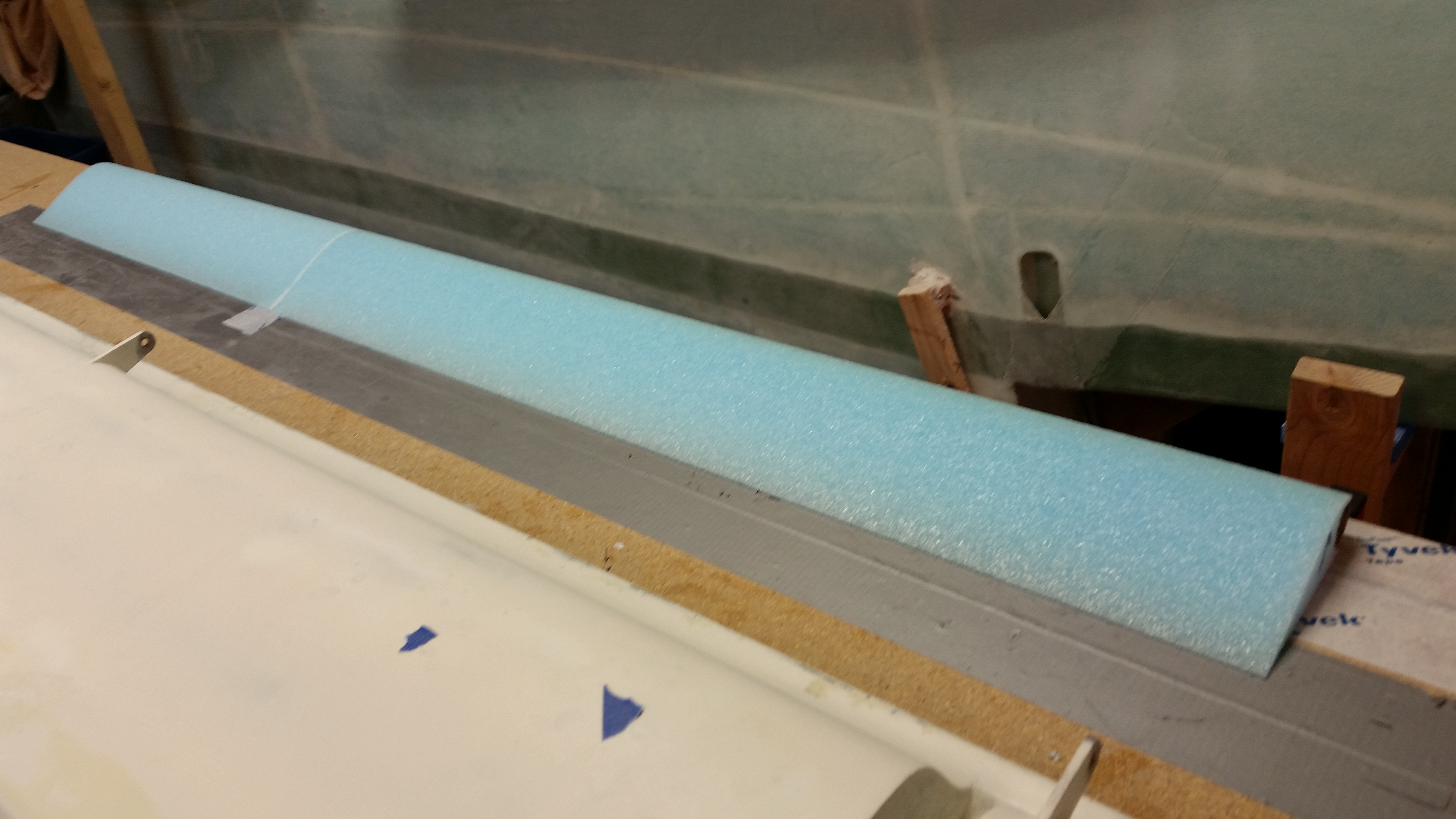
To keep the mess on the canard to a minimum, and to also keep the micro’d left elevator core as straight as possible, I decided to only micro the smaller of the left elevator foam cores pieces onto the tube. To start, I mocked up that smaller piece as you can see below. It fit perfectly and very snugly.

I mixed up some micro and micro’d on the smaller piece of the left elevator core. I ran a line from the right elevator TE to match the left elevator TE as closely as possible in trail to the right side.

Here’s a wide angle shot of the left elevator core piece installed.
And a shot from the top side of the canard.

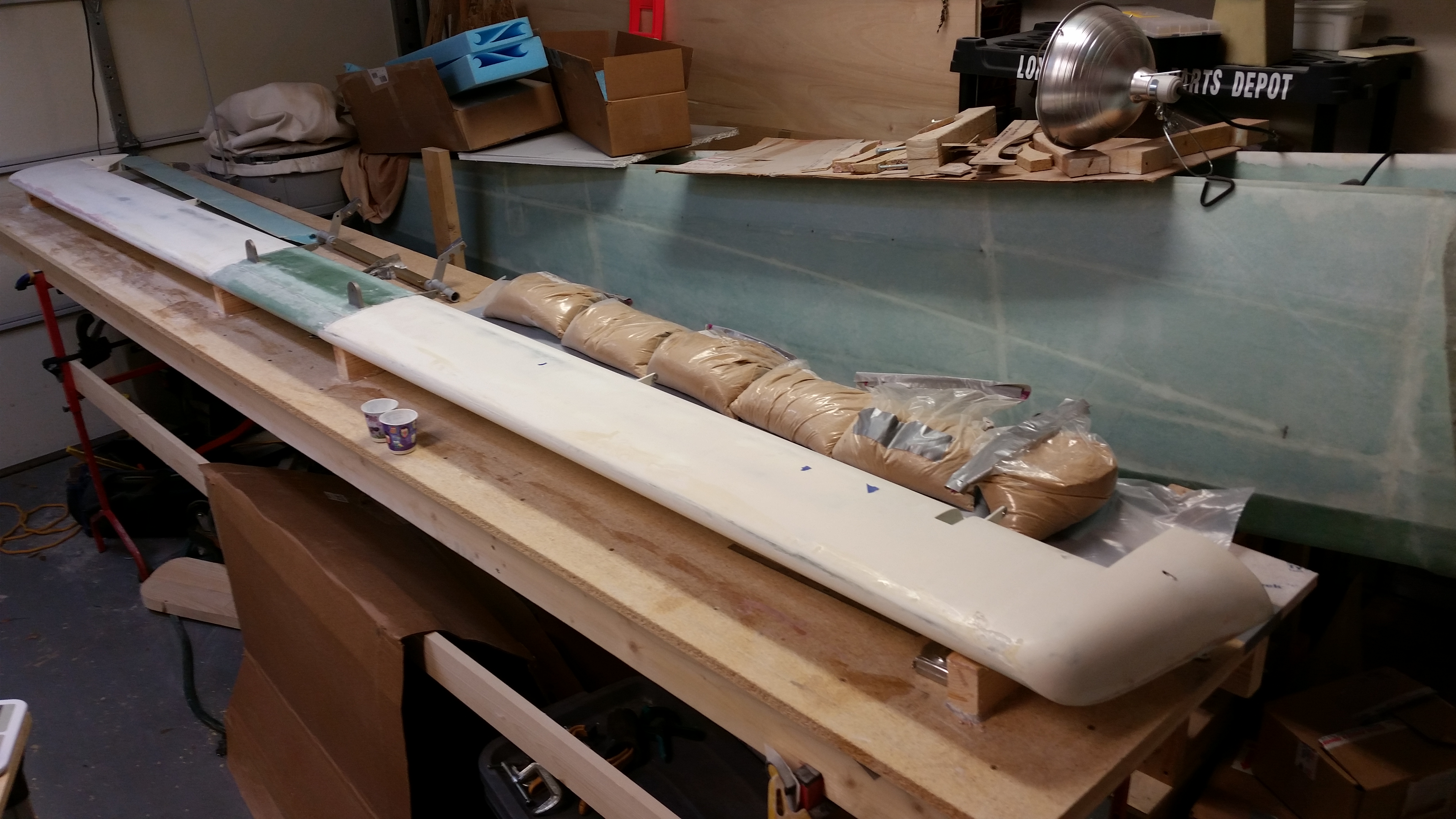
I let the micro cure for about an hour before dismantling the elevator assembly. With the smaller elevator core piece micro’d securely in place, I then merely mounted the remaining elevator core with micro.
And then weighed down the elevator core, specifically the TE.

Here’s a shot of the curing left elevator core micro’d to the elevator tube, and a shot of the entire canard back in a “normal” state.
Tomorrow I plan on finishing the major glassing of the left elevator, both top and bottom. As I’ve mentioned before, once I start getting close to finishing the left elevator, I’ll start ramping up more on the nose build.