Chapter 23 – Air induction System

I actually started this clear-coating process yesterday: I hit the air induction tube with 2 coats of clear coat and let it cure overnight.

Today I wet sanded the clear coat with 320 grit sandpaper before then again shooting 2 thicker coats of 1K clear.

A few hours later, after a good initial cure, I mounted the freshly clear-coated Fuel Injection Servo air induction tube.

I then trimmed and mounted the 9.5″ long segment of SCEET tubing between the RAM air can and the air induction tube.

Another couple shots of the installed segment of the SCEET tubing between the RAM air can and the Fuel Injection Servo air induction tube.

I then grabbed a shot to show the alignment between the air induction tube and the RAM air can.

I then installed the lower cowling to check the clearance between the Fuel Injection Servo air induction tube and lower cowling.  Because of the thicker tube wall than expected and fairly thick clear coat my clearance is a bit less than I had reached earlier… just under 1/4″. Obviously not as much as I’d want, but again I’ll take what I can.

I’ll also note that with my dialing in a straight shot between the air induction tube and the RAM air can, the air induction tube sits slightly to the right of center… which means it’s a tad closer to the right side cowling wall.

It’s not untenable, but it is something I’ll be watching… here’s one last shot of the just installed air induction tube.

Tomorrow I’ll be pressing forward with finalizing the air induction system configuration.  I’ll also be pressing forward with other engine components installs.

Chapter 21 – Strakes closed out!

Today was a huge milestone for my Long-EZ build in that I got the top strake skins floxed on and the strakes closed out.

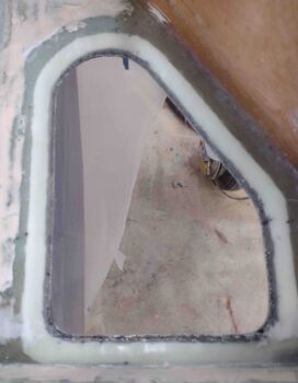
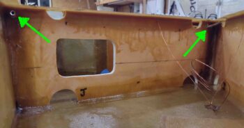
My first task of the day was just annoying, to be honest.  I found yet another epoxy bead from a tape seam as the light hit the left GIB strake window just at the right angle as I was looking through it. Ugh!  I wet sanded it with 600, 1000, 1500 and 2000 grit before buffing it out with my kit.

Done.  It better be the last time (ok, except for the outside… I know that’s coming!)

Not shown here, but I first taped the GIB windows and fuel site gages back up before sanding down the longerons in prep for layups.  I then vacuumed out the dust (both inside the baggage areas and the fuel tanks) before taping in plastic sheeting to protect the just-painted baggage areas from any epoxy or flox gunk that may ensue from closing out the strakes.

I then took a page out of Dave Berenholtz strake build and covered my open strakes with clear plastic to create a rib/T-hat/LE map for reference later on if I need it.  A 20 minute task that may prove very useful in the future.  Thanks Dave!

I then did a final fitting and prep of the strake top skins.  I also transferred and marked up the T-hat positions actually on the strake skin foam cores themselves.  I wanted to have a quick reference as to where to put the weights once these things were floxed on.

I then removed the strake top skins, vacuumed out the entire fuel tank each side, then removed all the protective tape pieces —fuel vents, drain screens, site gage holes— and then vacuumed again before doing a visual check for any bits of dust or lint.

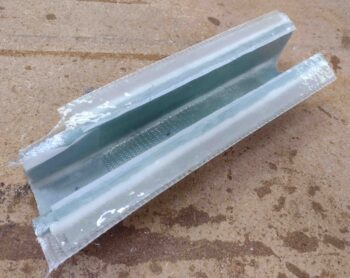
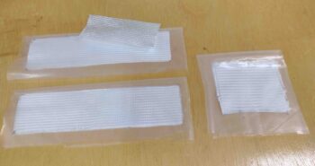
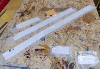
Unabashedly copying yet another builder, I then took a page from Ary Glantz’s strake build and made up single ply BID tapes that will be laid up on the longerons first, then overlapped onto the inboard underside edge of the strake skins when they’re put into position.  Much easier than the plans method of leaving an inch of glass overhanging down the inboard edge of the strake skin un-wetted-out to then be overlapped upward onto the longeron… as Ary essentially noted on his blog: use gravity as your friend.

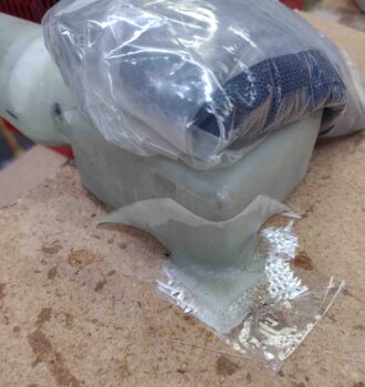
I then prepregged these BID tapes.

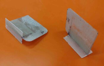
The smaller ~5″ wide BID tapes in the lower right corner of the pic are the ply of BID that goes from the inboard underside edge of the strake skin and overlaps onto the longeron, only in the very aft where it is sitting on top of the T-hat/flange… so these are separate layups that I used EZ Poxy to layup.  I laid these up on the aft edge of each top strake skin.

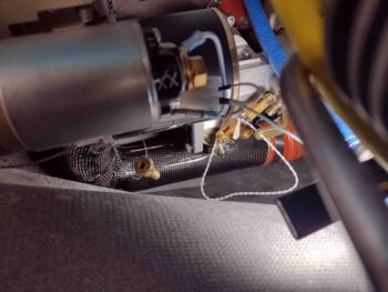
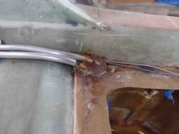
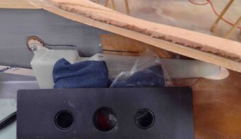
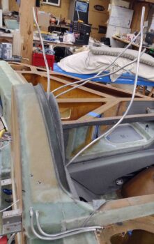
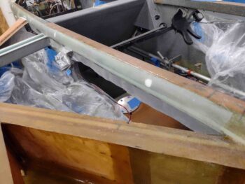
I then laid up the forward, longer BID tapes on the longerons using MGS 335 epoxy with a 50/50 mix of fast and slow hardener…. here’s the right longeron with the BID tape in place.

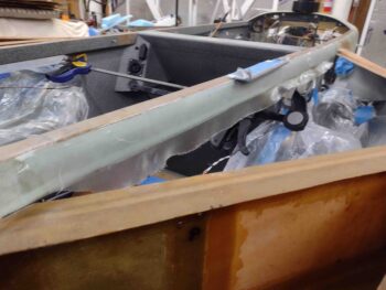
Ahem! I got a little cocky here and should have gone slow hardener all the way because these BID tapes were getting pretty dry by the time I got the actual flox on all the T-hats and strake top skins set in place.  I made it though… just barely.

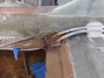
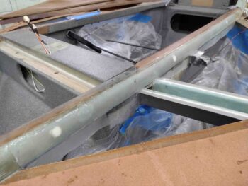
Here’s the left longeron BID tapes.

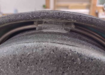
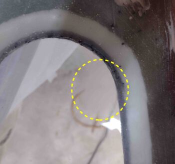
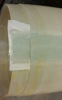
I will note that I set the left strake in place first and then moved onto the right side.  At some point I had a bit too much weight in the area above the GIB strake baggage opening. The weight caused this layup to pull back/away a bit as the surface it was attached to moved further down/away.  As I rebalanced the weight on the left strake top a bit later, I wasn’t thinking about that layup.  So once the top skin came back up to its proper position, and with the BID tape well into curing, it simply pulled it upward in its now “elongated” state…. in short, I have a decent bit of bunching right along the longeron bottom/inboard skin seam on the left underside baggage opening.

I clamped the top skin and the longeron to bring the position to the correct height as it fully cured.  I’ll wait to fix this until after I glass the outside tops of the strake so it’s stronger and has support to secure this segment of the top skin edge into place.  Thankfully the right strake is fine.

Since I had just a half of a squeeze bottle left of E-Z Poxy 87B hardener left and a bunch more 84B on hand, I prioritized my hardener usage so that I would ensure the actual perimeter of the fuel tank was secured with E-Z 87B hardener (the best stuff according to Gary Hunter) and then the middle/inside rib tops/T-hats got the E-Z 84B hardener.

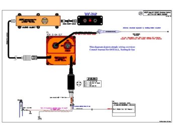
Here’s my chicken scratch drawing of my plan:

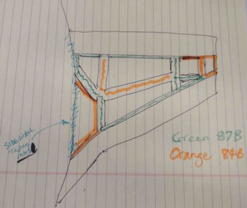
And here it is in application.  Actually the left strake got pretty much exactly what you see above, while I was able to use the 87B on a few more areas on the right strake since I knew I was in the clear.

Although I do have probably just enough 87B for the initial floxing in of the fuel probes.

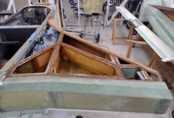
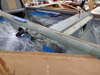
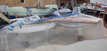
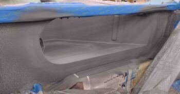
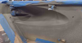
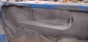
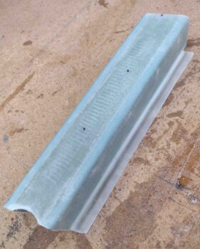
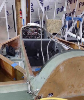
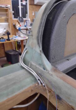
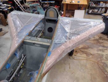
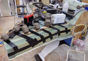
I would call the above the “before pic” while this one below is the “after pic”… with the right strake top skin floxed in place and tons of gym weights and other items weighing it down in place . . .

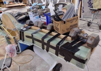
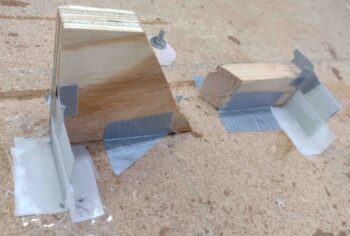
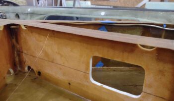
as well as ACS shipping dunnage wood strips taped in place to really get a good compression on the front edge of the foam where it overlaps the leading edge flange.

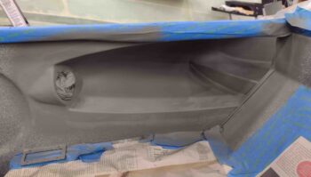
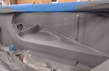
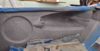
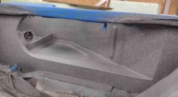
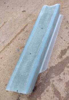
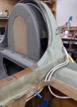
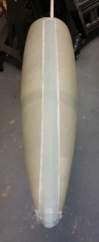
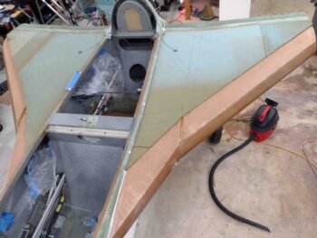
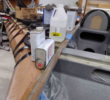
Here is the front side of the right strake closeout.

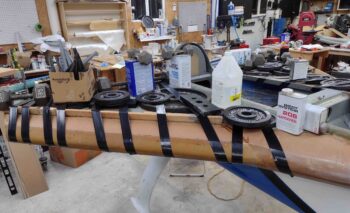
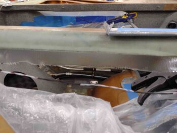
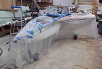
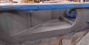
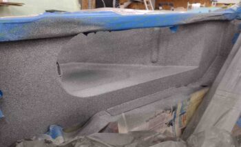
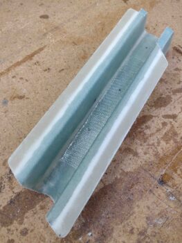
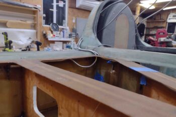
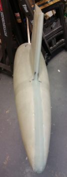
The left strake was actually the first side I closed out.  Here’s a shot of that.

You can see I used a lot more standard gym weights on the left side, which is why I had to get more creative on the right side and use other heavy items to weigh it down.

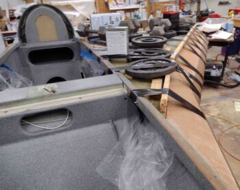
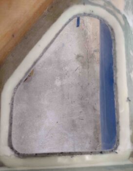
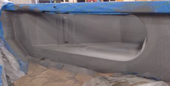
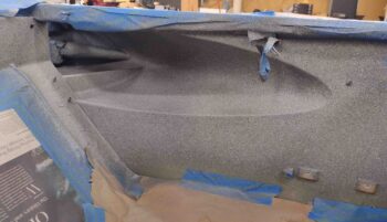
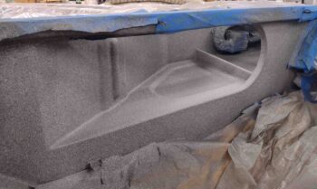
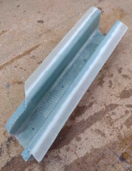
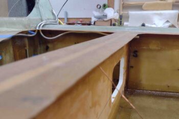
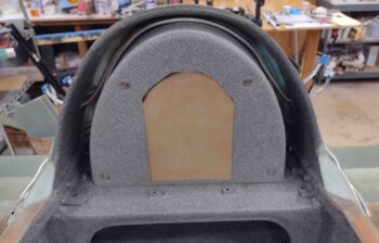
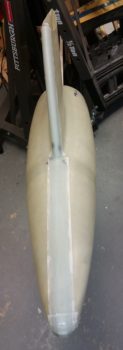
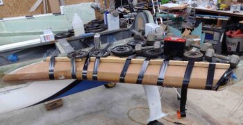
Finally, here’s a shot of the aft side of the left strake top skin closeout.

It was quite late and a VERY long day… time to have a glass of red and celebrate this milestone before jumping back into the fray!

Chapter 21 – Baggage areas painted

I started off this morning by removing the clamps and the spacers to reveal my flox and glass gatekeeper to keep the fuel vents wrangled in the Turtledeck.  While the glass and flox certainly did the job, it’s interesting to note that the pressure I put on the layup squeezed a good bit of epoxy out of the glass layup and made it fairly dry.

I also grabbed shots of the E-Z Poxy floxed fuel vent lines exiting the aft corners of the fuel tanks via the flange.  I peel plied them since there will be more added to these flox bits when the strake tops get floxed into place.

I then gathered up some 600, 1200 and 1500 grit sandpaper and wet sanded the scratch on the aft end of the left GIB strake window.  If you focus on the electrical cord on the ground you can see how it disappears into a haze… that haze is the wet-sanded scratch.

I then buffed out both the right and the left GIB strake windows… and with the windows pretty much scratch free on the inside, it was time to tape them up for paint.

I also taped up a whole bunch of other things as well in prep for paint.

And covered a bunch of areas with plastic to ensure anything that was not supposed to get paint, didn’t.

I then broke out the primer and hit the pilot right baggage opening.

As well as the GIB right baggage opening…

then the left side in the back.

And finally, the left pilot baggage opening.  I have to say, I really like this gray… too bad it doesn’t cover as well as the gray granite paint.

After a good 30 minutes plus, I then painted the inside of the baggage areas and fuselage with the Rustoleum gray granite paint.

I was a bit concerned with how well it would blend with the previous paint, but thankfully it looked like it came out of the same can!  As I always say: better to be lucky than good. Ha!

And the last couple of shots.  All these pics were taken after I shot the second and final coat of paint.

I’m extremely pleased with how the paint looks.  Moreover, I’m glad I took the time to micro up the various spots of the baggage areas to smooth out the rough stuff.

Tomorrow I’ll shoot a couple rounds of clear coat before moving on to the outboard strake storage compartments and preinstall on the fuel probes.

Chapter 21/22 – Target: Cabin Heat!

This morning I started out by popping free the oil heat RAM air scoop cross duct/bridge from the clear packing tape I laid it all up on.  If you remember, I put peel ply down first before laying up the flanges.  I also peel plied both ends for any added plies of glass that will be required.

I then pulled the peel ply and razor trimmed the glass.  Here’s a shot of the outside, which is actually the bottom of the duct/bridge and the sides of course… a shot each end.

I then took a couple of shots of the inside as well.,, again, from each end.

I then got started on the myriad of nitnoy tasks.  First off, I made up the vapor fins that will get attached inside the vapor box, the forward one hanging down from the top of the box, and the aft one attached to the floor.  This will make the air have to do a couple of slalom weaves to get into the air duct… which should significantly help pull the moisture out of the incoming air.

To assist with laying up the back (outboard) wall of the vapor box, I am glassing mini “T-hats” to the outboard edges of the fins to provide some bridge supports for the backside glass.  That’s what all this commotion is in the pic below.

Also, at the very top you can see a spare, previously-glassed piece of 3/8″ PVC foam that I’m using as a pedestal/spacer for the Vapor-box mounting tab Clickbond (see next pic)

. . . the Clickbond to go through this tab which will be attached to the upper aft corner of the Vapor Box with flox & glass.  Note that the tab itself is G10 phenolic.

I then mixed up some epoxy, laid up the T-hat glass on the Vapor Box fins and also floxed the Clickbond to its foam/fiberglass pedestal.

Here’s a shot from the other side.

And here we have the Vapor Box mounting tab floxed and glassed into place with 2 plies of BID.  I peel plied this layup as I did the T-hats above.

Quite a few hours later I significantly decreased the width/depth of the Clickbond base and then micro’d (since I removed the backside glass) it to the BL23 rib… with just a dab of 5-minute glue in the middle to help secure it quickly.

My last task of the evening was actually a REAL build task, as per plans (and CP). I ran the fuel tanks’ vent line tubing from each tank, through/up/over/down the Turtledeck to then pop out the other side.  This is how Chris Randall did his fuel vents and it seemed the easiest of all solutions, so I followed suit.

Here we have the right fuel tank vent lines in place.

And here’s the forward vent line in the left fuel tank in the top pic, and the aft vent in the bottom pic. I’ll note that with all the extra bending and machinations that I went through to get these vent tubes in place, they are not the straightest or prettiest vent lines you’ll see… but they work.  And once the tops are on these strakes hopefully none of us will ever see these ugly things again… ha!

The fuel vent lines coming out from around the GIB headrest reminded me of some sea creature on the ocean floor, tentacles at the ready in search of food… but I digress!

Here’s a shot of the vent lines going through the flange I created to flox the upper strake skin to… note that since I have Mike Melvill’s cowlings that there are shoulder bumps that come forward of the cowling in the corners between the strake and Turtledeck.  Thus, to keep the vent lines out of the cockpit, and put the transition holes out of the tank on the top vs the side of the tank, I ran the fuel vent tubes along the aft longeron to then upwards into the Turtledeck.

Another shot of the fuel vent line tubing, both on the side of the longeron and entering the Turtledeck.  Ok, and the weird stuff coming out of the middle!

It took a fair bit of finagling to get the lines around the top of the GIB headrest and out the other side, but I eventually got them all.  Thank God I gave myself extra length on these tubes, because I tore the ends to hell getting them out of the interior Turtledeck.

After I layup all the extra glass on the Turtledeck for the top cowling mounting flanges and then micro finish it in prep for paint I’ll trim the fuel vent lines flush with the surface of the Turtledeck.  Again, this is how Chris Randall did his and he has a ton of years of trouble free flying with his fuel vent tubes configured this way.

I’m not overly pleased with how these vent lines look inside the Turtedeck and I am honestly pondering how best to hide them.  Regardless, there they are in their current state.

BTW, here’s how those Vapor Box fin T-hats turned out… not bad for a ply of BID each side.

After I did my minor/myriad tasks above, I took a bit of time to make up prepregged 2-ply BID tapes for the duct/bridge when it comes time to glass that in place.  I also prepregged 2 plies of BID for the aft/outboard wall of the Vapor Box to close that out.

And with that… I definitely called it a night!


Chapter 22 – New Wiring Diagrams

Yeah, not a lot going on as far as actual building, but I am getting some of the low hanging fruit –which does take a good bit of time– out of the way.

To start off, I did get my 15 amp mini-ANL fuse delivered.  Just for sake of closure here’s a shot of it installed in the fuse holder.

In addition, over the last couple of days I’ve created wiring diagrams for the ACK E-04 ELT:

the Trio Pro Pilot Autopilot:

And the GRT HUD system:

I do have a bit of final cleanup stuff and crosschecking to do on each of these diagrams, but for the most part they are complete.

Finally, in the next few days I plan on knocking out the Trig TT22 Transponder wiring diagram, which at this point is the last wiring diagram left to complete.  Moreover, I’ve made updates and tweaked about 10 other wiring diagrams so my electrical system documentation is pretty up to snuff currently.

I’ll continue to update you all on any minor bits of progress or massive decisions that I make on the build as they occur!


Chapter 22 – E-Bus Feed Fuse

From my research this was the best Mini ANL (MIDI) fuse holder that I could find to serve as my new E-Bus feed fuse holder…. and I quite like it too.  It’s lightweight (1.4 oz) yet quite sturdy and simple in design.  As you can see, it has two #10 screw posts which each serve double duty to both retain each end of the Mini ANL fuse/current limiter and secure the respective wires’ terminals to the fuse holder.

The actual nomenclature for this component is the EATON Bussmann LMI1-E-2-0 Fuse Holder with Cover.

The attached red rubber protective cap simple pushes into place –with slots on the underside of the cap– onto the center vertical posts that are situated above and below the center fuse area in the pic above.

Below are pics with the red protective cap in place.

And here is a representative shot of the Mini ANL (MIDI) type fuse, which of course is just a smaller version of the more robust 40-60A current limiters often seen in many experimental airplanes on the alternator’s B-lead circuit.

I looked around at a couple of auto parts stores in hopes that they would have these Mini ANL (MIDI) fuses in stock, but alas, I ended up having to order them online.

So I now have all the components identified/on-hand/on order to make the modification in my conversion to Bob Nuckoll’s new Z-36 E-Bus feed circuit, which IMO is much better than the previous circuit design I was using.


Chapter 22 – Electrical System Tweaks

My current back ailment puts me in a bit of an irony at the moment: since I want to take it EZ for a good bit to let my back and hip heal up, I am now actually able to do some much needed administrivia and cleanup tasks on the electrical system.  Kind of a catch-22 scenario at the moment in that the longer I delay on getting my house sold, the longer it will take to get back on the build… but in my current state, I’m actually able to focus on a number of aspects of the build.  Life can be weird sometimes!

To start off, Bob Nuckolls must be bored (or something!) as he’s been ginning up some new Z diagrams to tweak some of his older stuff.  Well, over a year ago he reviewed my basic electrical system architecture and signed off on it, but in the process told me that I didn’t need a relay that I had in place to control isolating (powering) the E-Bus to SD-8 b/u alternator power when/if I had a main alternator failure.  I removed the relay to simplify and lighten my system, but never had a 100% warm fuzzy on doing so. I also wasn’t keen on my entire E-Bus being powered via a 15A ATC blade fuse off the Battery Bus.  ATC blade fuses tend to be a bit more on the fast-blow side so they are more likely to nuisance trip, so the sizing is a bit more touchy on critical components than say a slower-blow CB.

Well, Bob has since remedied both those issues with a new Z-36 design (see below), which I quickly scarfed up and implemented into my system architecture.  Not only does the new Z-36 put the relay back into play, but it feeds the whole E-Bus circuit from a much more robust ANL fuse.  Since I wanted to go with a lower amp rating than 30 amps (depicted on Bob’s diagram), I actually downsized to a MINI ANL fuse and will be using either a 15A or 20A mini ANL fuse. During my research, I was also able to find a good fuse holder mount for it and pulled the trigger on it.

I updated my master electrical system diagram to show this modification, which significantly changed my wiring circuitry to/from the Battery Bus & E-Bus for the b/u alternator power feed, and also the switch circuitry that drives the switching from main to b/u alternator/E-bus power.  Luckily, I hadn’t really wired any of that up so I won’t have to do any major rewiring work. Now, while the logic of my configuration matches Bob’s Z-36, my mechanical implementation is just a tad different than his, as I show here (focus on top center of diagrams):

In addition, I spent a bit of time reworking the AEX switch on Marc Zeitlin’s new gear architecture to add an “OFF” position [which, BTW, Marc had in his original design and I am now putting back in based off the advice from Joe Coraggio in his recounting his off-field landing].

My new switch’s wiring is not exactly how I would design it if I were starting from scratch, but it will definitely work and –moreover– will keep the aviation standard of the bottom switch position being “OFF.”  It also eliminates any extensive re-wiring other than lopping off the wires from the current switch and re-soldering them to the new OFF-ON-(ON) switch.  So, on the new 3-position switch, the bottom position is OFF, the middle position is AEX AUTO, and the top momentary position is Emergency Gear Extend, as shown here.

If you’re wondering what switch I’m talking about and it’s location in regards to the panel, I’ve circled it in white and have an arrow pointing to it.  Yes, it’s the one in the black and yellow striped switch guard.

I also took a bit of time while adding the new Z-36 design into my system to do an inventory of all my relays and inline fuses.  I found a couple of discrepancies in the component ID numbers due to repeated additions, changes and swap outs during system design.  I’ve cleaned up the IDs and the lists so I’m up to snuff with both of those electrical system component categories.

My final task related to the wiring was that due to a variety of reasons (from limited behind-panel space to near-max antenna cable run) I decided to place my Trig TT22 transponder out in the right strake pocket and worked up the new wiring scheme for that.  I’m actually running the power wires via the CS spar conduit from the hell hole, so that only leaves 4 x 22AWG signal wires that I’ll need to run through a nylaflow conduit imbedded into the lower front LE of the strake.  While working the wiring for moving the Trig TT22 out from behind the panel to the end of the right strake, I also finalized the configuration for another (2 of 2) consolidated 22AWG 6-wire cable that will start behind the panel and end in the hell hole.

In addition to working my plane’s electrical system taskers, I’ve also been getting back into the books on flying, IFR and avionics.  I’m hoping to get back in the cockpit for another 1-3 months during my transition down to NC to get my flying “sea legs” back underneath me!

Chapter 23 – Camshaft bath time!

Today I carved out about an hour from house updating tasks to bake a couple of batches of desiccant to reinvigorate the moisture absorbing power of this magical stuff.

Part of that process was pulling the cylinder dehydrator plugs to replenish them as well with the high-octane desiccant.  I then replaced the freshly pulled dehydrator plugs with spark plugs and then flipped the engine inverted to bath the camshaft and upper areas of the crankcase with oil.

After I inverted the engine I then replaced the bottom spark plugs with the freshly replenished & renewed dehydrator plugs.  As I pulled the plugs on a couple of the cylinders I used a flashlight to take a peak inside the cylinders to check out the condition in there.  The walls and a bit of a piston in both cylinders that I checked were wet with oil and shining bright as a new penny ( . . . or maybe a dime, since it’s silver colored?!).

Happy with what I saw I tried my best to grab a pic of the cylinder wall, which you get a general idea of in the shot below.

I’m really happy with this engine stand and appreciate being able to get the camshaft soaking in a bath of preservation oil.

When I inverted the engine this time around, I made sure to run the output line from the engine dehumidifier into the cold air induction plenum opening, which I then ensured was as taped closed as possible (sorry for the not-so-clear pic!).

I also installed some Lycoming exhaust manifold port covers that I picked up from ACS. They cost a bit but I’ve been so busy –with no time to roll my own– that I went ahead and pulled the trigger on them. Also, as you can see, again I loaded up the dehydrator plugs with fresh desiccant.

[NOTE: At the very bottom edge of the pic below you can see a drop of oil near the clear tubing.  I found that the fuel injection nozzle port was dripping oil so I tried my best to tighten the fittings.  I got a little bit of the main fitting and good bit of the smaller fitting, and slowed the drip down considerably…. but I will need to sinch up the fittings a tad more to ensure the leaking is stopped.]

In addition, I threw away the tired desiccant packs that I had stuffed inside the exhaust manifold ports a while back and should be getting a batch of good-sized fresh desiccant packs within the next day or so to replace the ones I threw out.

I have been meaning to invert the engine for weeks now but of course had to deal with swapping plugs, refreshing the dehydrator plugs, baking desiccant, etc.  I’m really glad that I was finally able to get this done and all still looks spiffy-keen with the engine!


Chapter 19/23 – Baggage pod break

I took a short break this morning to pull the peel ply and clean up the edges of the major CL seam layup on baggage pod #1.

Later this evening I laid up a 4 ply pad of BID on the aft bottom end of baggage pod #1 that will serve to reinforce the lip for attaching the baggage pod aft cone.

I then laid up 3 plies of BID around the main CL seam on baggage pod #2 just as I did on the first baggage pod last night.  I then peel plied the layup.

While I was looking at some pics tonight I found a shot of the cowlings from around 2012 that had a document included that I haven’t seen in quite a while.  While looking for the document I finally completely unwrapped the Berkut-style armpit intakes for the lower cowling.  As you can see, I decided to grab a couple of shots of these to include in this blog post…

Again, with my house updating shenanigans I only have a couple of hours a day that I’m allowing myself to work on the plane build.  However, I figure every hour counts and gets me much closer to the finish line!


Chapter 3/22/23 – Back at it!

I just returned from my North Carolina sortie late this afternoon.  I of course had to attend to some normal life stuff before getting back into the groove of things.

I would like to actually start out by reporting on a couple things I did/noted before I left for NC.  The first is that before I left out I flipped the engine inverted and recharged the cylinder dehydrator plugs with fresh desiccant.  Since I have 4 of the these dehydrator plugs I removed them from the top plug holes on the cylinders and replaced them with standard aircraft spark plugs before flipping the engine upside down. [This is a previous “stock” pic I took of the engine positioned inverted on the engine stand… it’s mislabeled stating that it was inverted only for a few hours vs 5 days].

After replacing the desiccant in the dehydrator plugs I then pulled the 4 standard aircraft plugs on the bottom of each cylinder (of course facing up at this point) and replaced them with the dehydrator plugs.  Since the oil filler cap was facing downward and the top mounted crankcase vent would leak into the Engine Dehumidifier air lines if I tried to attach it to the inverted engine, I just left both unconnected for the duration of my trip.

In addition, as I was packing up for taking a load of household stuff down to NC, I found my cardboard mockup of the Trig TT22 transponder.  It became readily apparent why I thought the actual TT22 unit was much smaller than I expected as I realized why when I compared the two.  The dimensions for the TT22 unit are given from the tip of antenna jack to the end of the wire mounting spring clip on the other end.  Clearly the box section of the unit is not included in those dimensions, making it much smaller in real life than my mockup.  Just an observation I had in how there always seems to be some sort of wrinkle in the planning of this stuff for the aircraft build.

So I got back home late this afternoon from NC and immediately kicked off an overdue Seattle Avionics chart data update for the GRT HXr EFIS (I missed the previous one… ).

In addition, the desiccant I left in the oven while I was gone was clearly saturated with moisture and had turned a bright light pink, so I fired up the oven to refresh the desiccant to its desired brilliant blue state.  A while later, after letting it cool a bit, I put it back into a sealed container to use in the Engine Dehumidifier after I flip the engine upright tomorrow.

Also upon returning home I found that some packages had arrived, including a digital tachometer and project box (to mount it in) from Ebay for the lathe.  Since I had to make a Home Depot/Lowe’s run I decided to do a quick check of the upcoming tach install to ensure I had all the components I would need on hand…. which I didn’t so I ginned up a list.  While I was at it I spent another 20 minutes mounting the lathe Quick Change Tool Post (QCTP) onto the lathe compound/cross slide/carriage.

Once the heights of the various lathe turning/cutting tools are dialed in, the QCTP will allow me to swap out tools in literally seconds vs tens of minutes.  Below are examples of a parting (“cut-off”) tool [top] and a turning tool [bottom], each in their respective tool holder [the attached tools are from a cheaper carbide tipped “indexable” tool kit I picked up from Harbor Freight, since it had good reviews…. I’ll use these tools as part of my kit starting out so if/when I break them during initial lathe ops, my cost of learning will be cheaper!].

Late this evening I did some final updates on my nose and canopy build task lists and printed those off in prep for starting back on these builds tomorrow.