
Chapter 10 — Roncz Canard
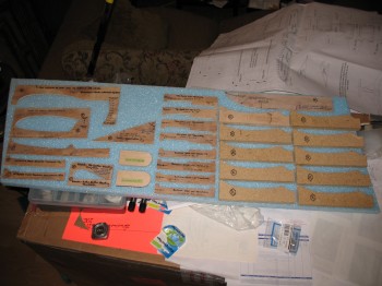
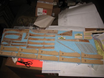
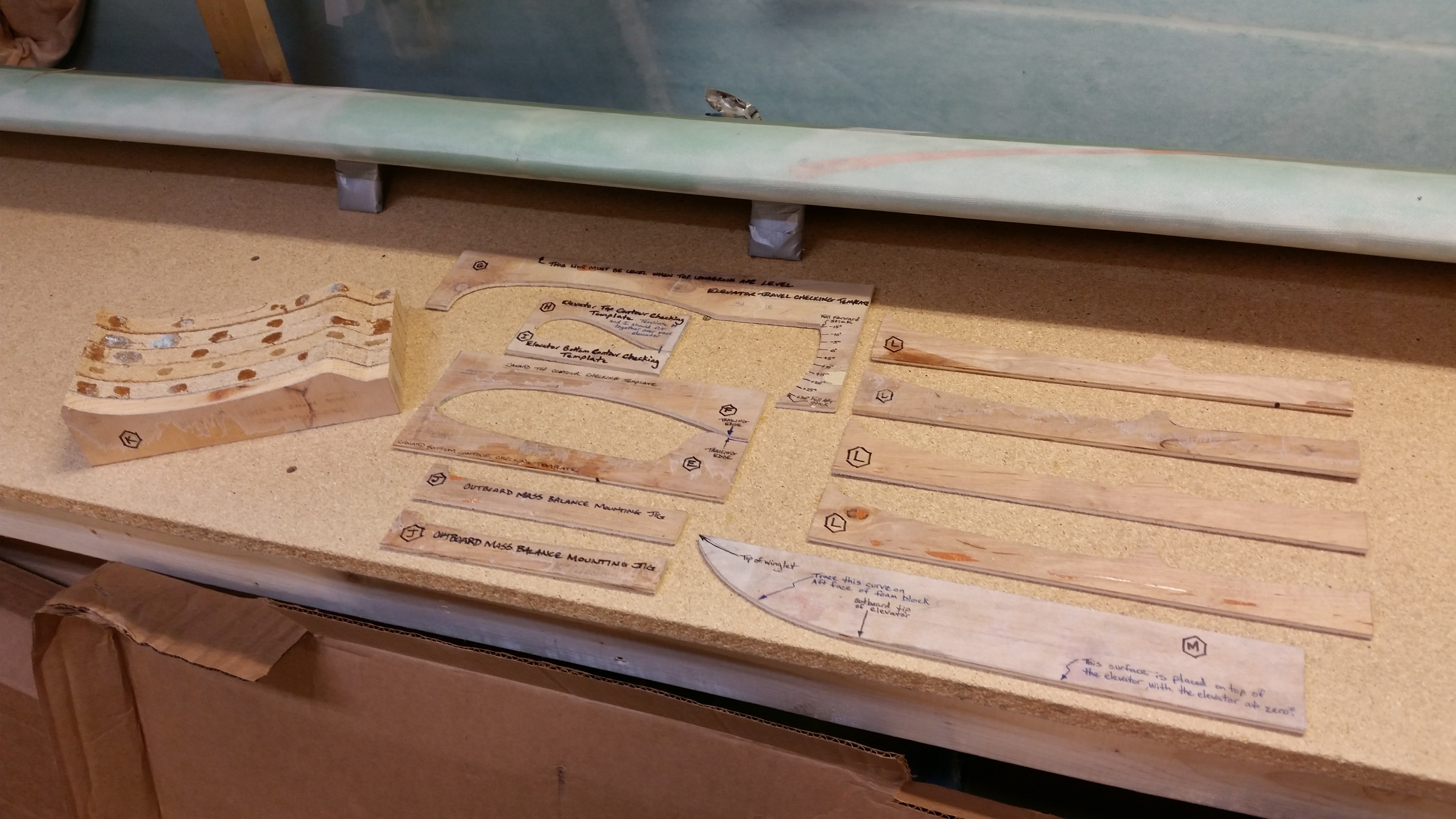
1 September 2012 — Today I spent about 2 hours at the Ramstein base wood hobby shop finishing & cutting a bunch of templates, jigs & parts–mainly for the Roncz canard build.
•••
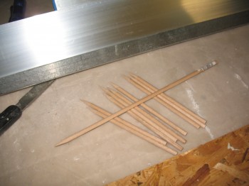
14 September 2012 — Today I started the build at the base wood hobby shop. I cut the remaining L-templates for the Roncz canard, and cut outlines of the CS109 cockpit control system mount & RT3 Roll Trim bracket. Additionally, I cut 10 x 6″ dowels & 1 x 12″ dowel for the Roncz canard & sharpened them all to a good point using an old school pencil sharpener.
•••
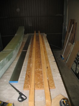
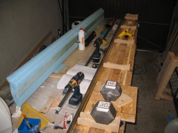
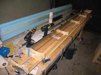
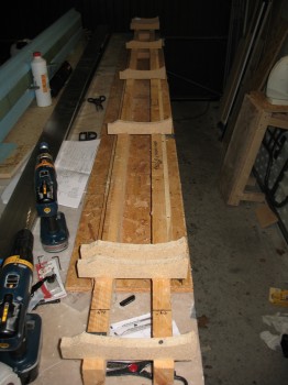
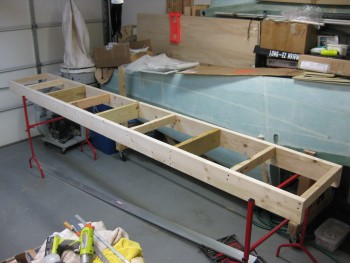
25 April 2013 — Today I started constructing the jig for the Roncz Canard build.
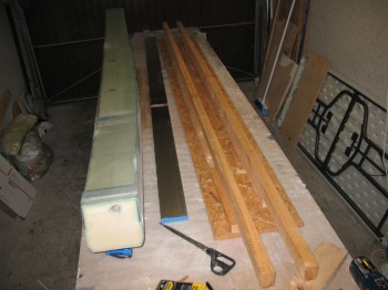
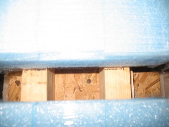
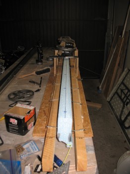
To make the canard jig as straight as possible, I mounted the 2×4’s first in an “L” shape to each other (one “L” for the front, one L for the back). I then mounted these 2-piece 2×4 “L” shapes to a straight panel of OSB flooring material. This all worked to make a pretty darn straight jig for the canard build.
•••
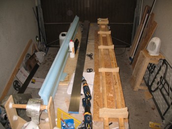
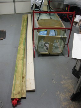
26 April 2013 — I picked up some 4″ nails and another, longer straight aluminum straight edge “board” from Praktiker today. Now I’m ready to start my Roncz Canard build in earnest.
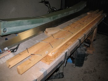
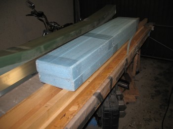
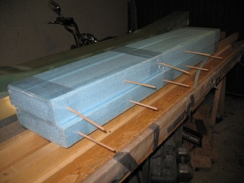
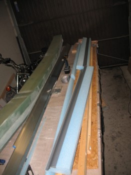
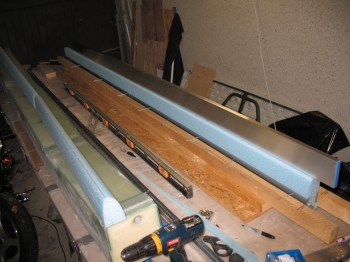
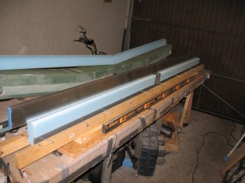
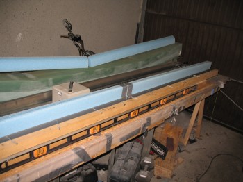
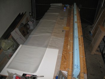
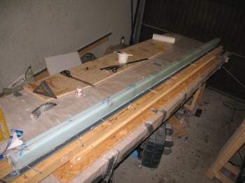
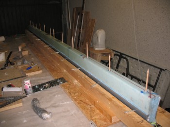
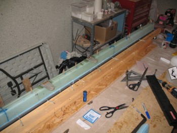
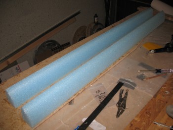
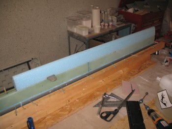
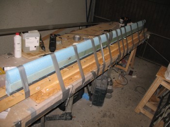
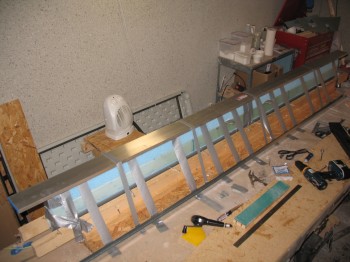
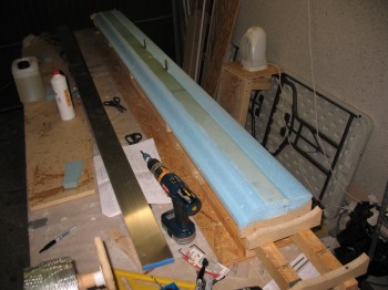
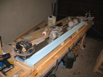
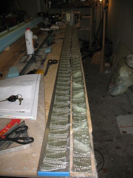
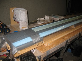
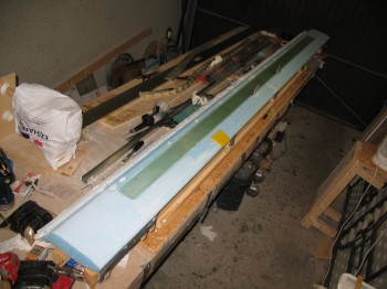
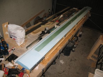
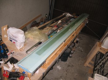
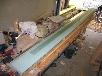
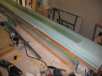
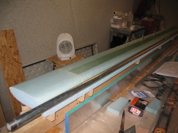
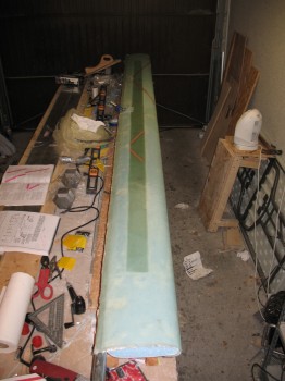
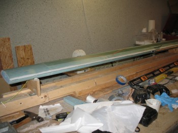
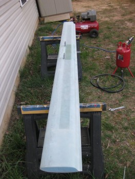
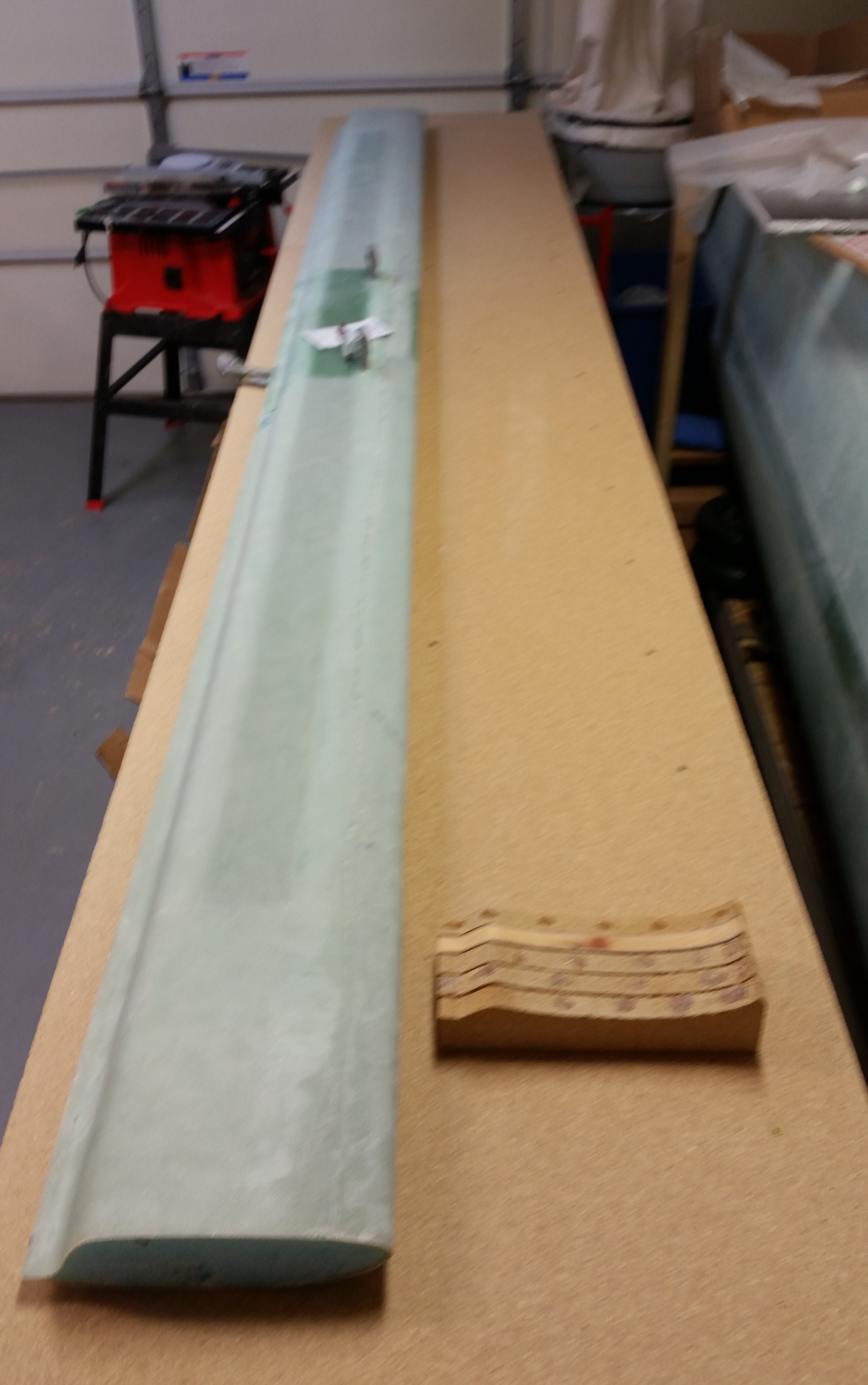
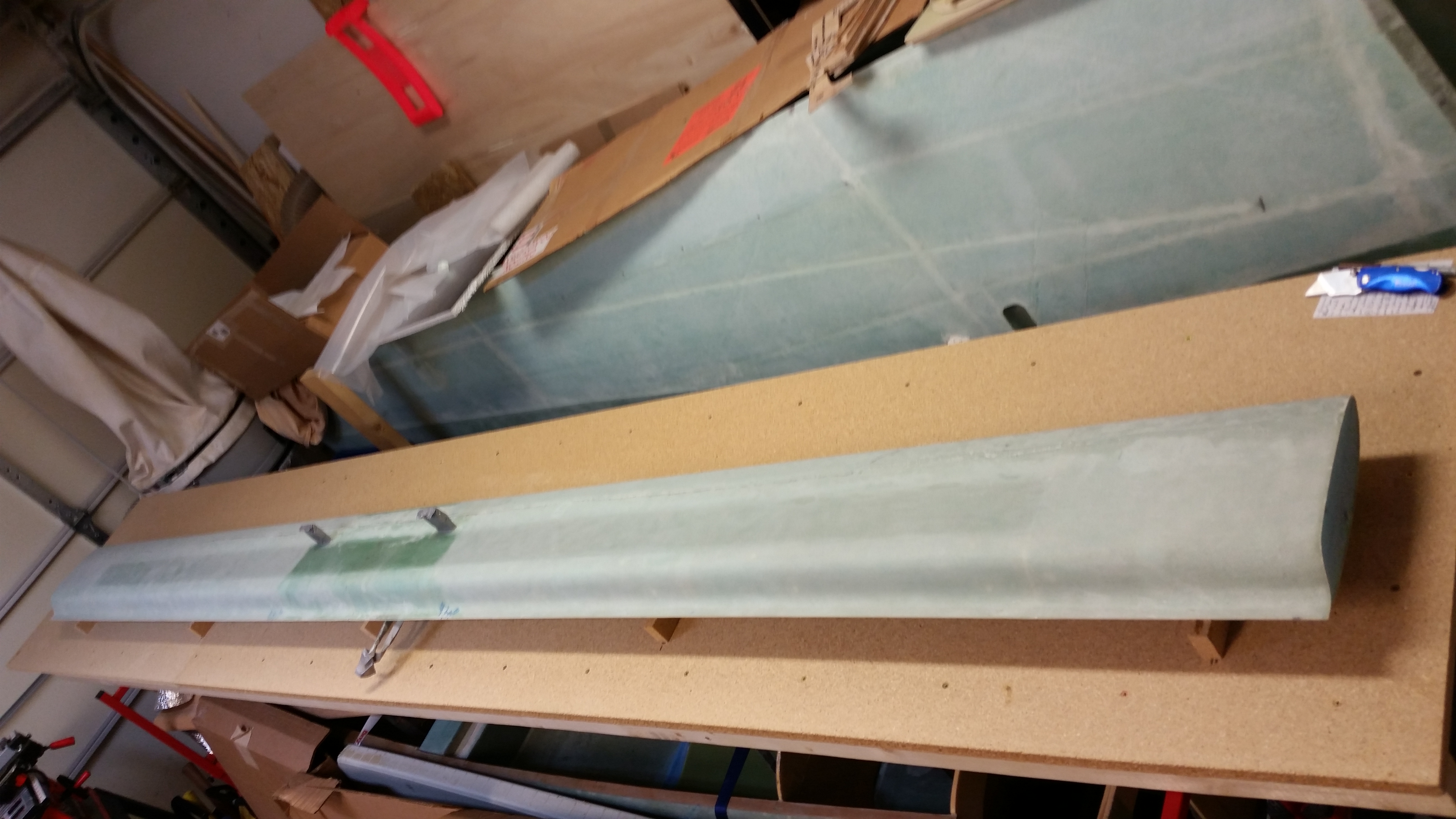
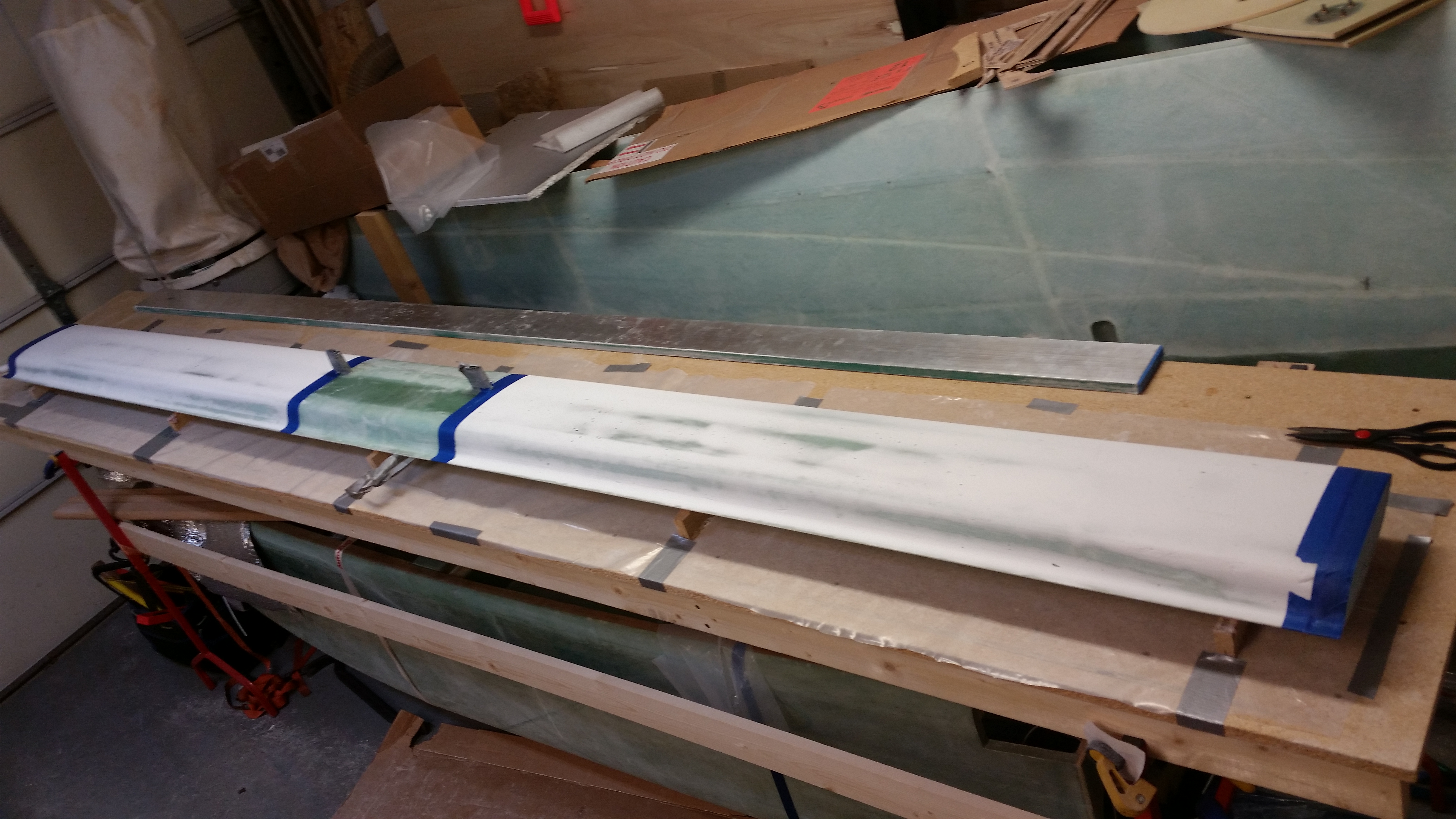
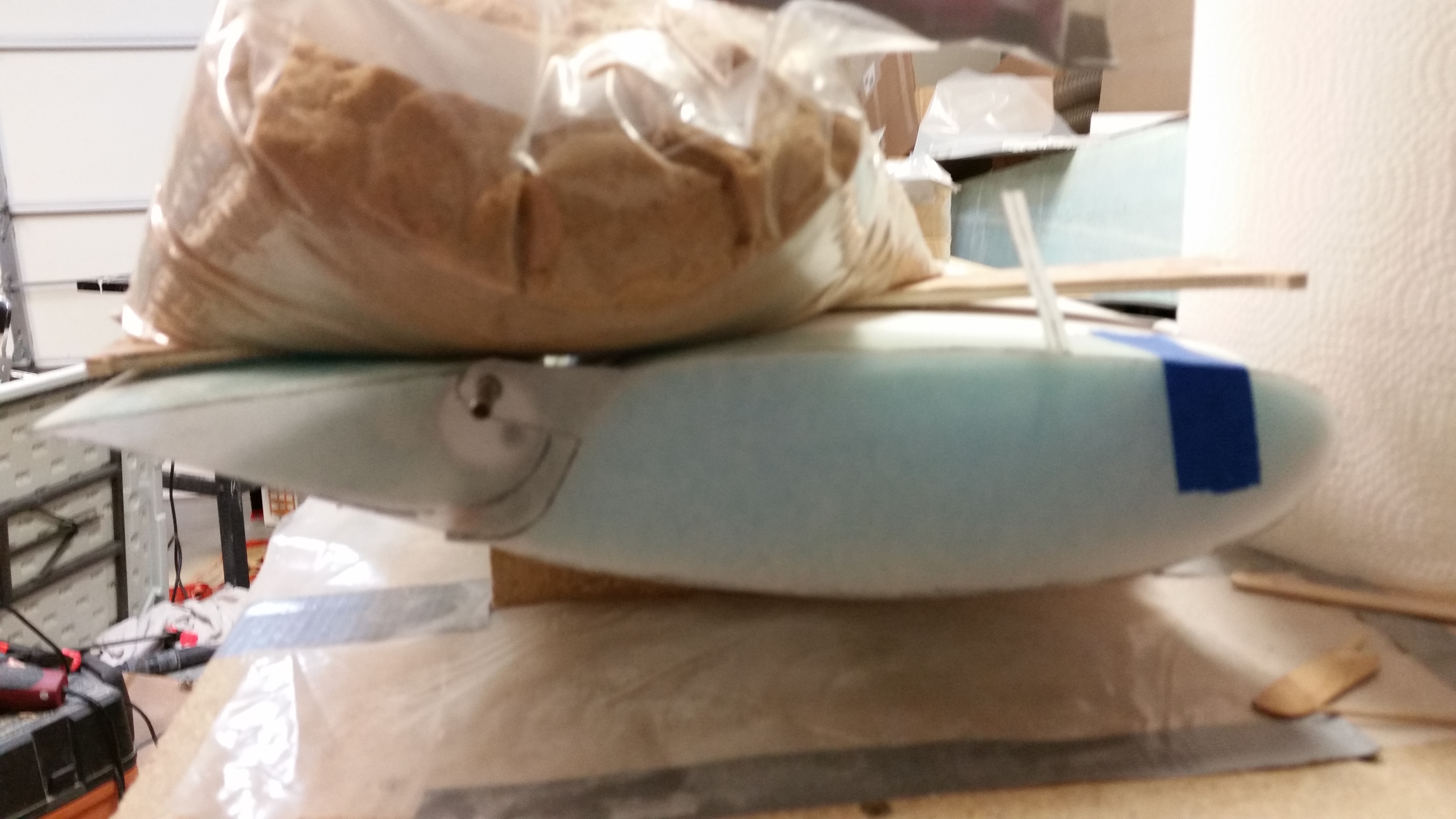
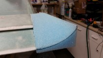
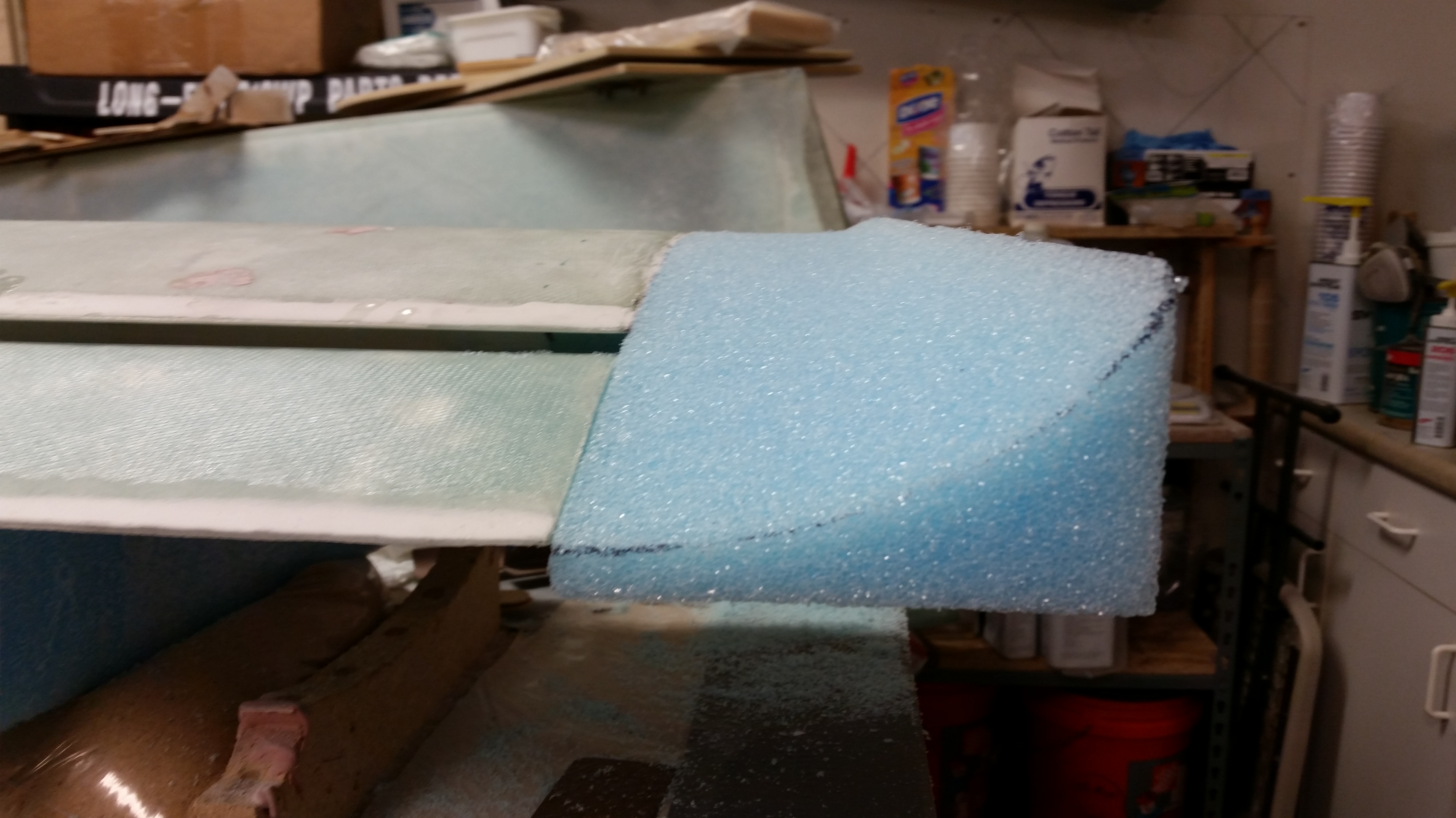
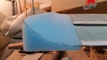
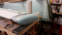
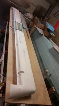
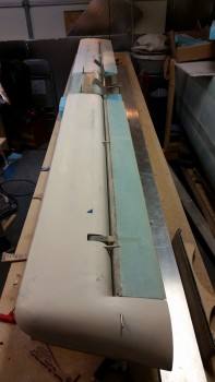
After finalizing the Roncz Canard Jig prep, I pulled the foam canard cores out and started aligning them on the jig.
BTW, the Roncz Canard build uses a completely different set of plans than the original plans. Now, that being said, the Roncz Canard Plans quite often refer back to the original plans Chapter 10 to accomplish many of the build steps.
I broke out my sharpened wooden 1/4″ dowels I made last September.
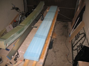
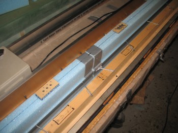
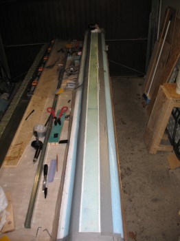
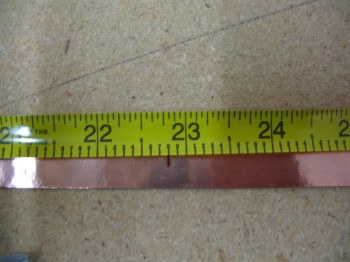
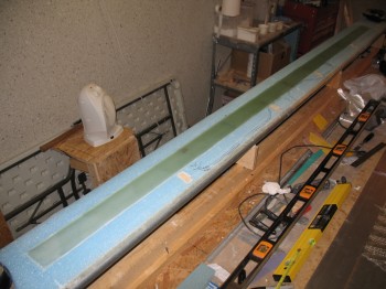
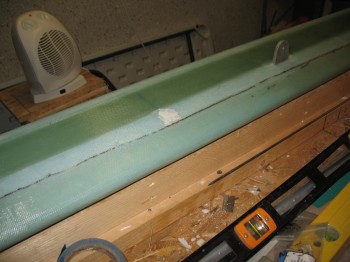
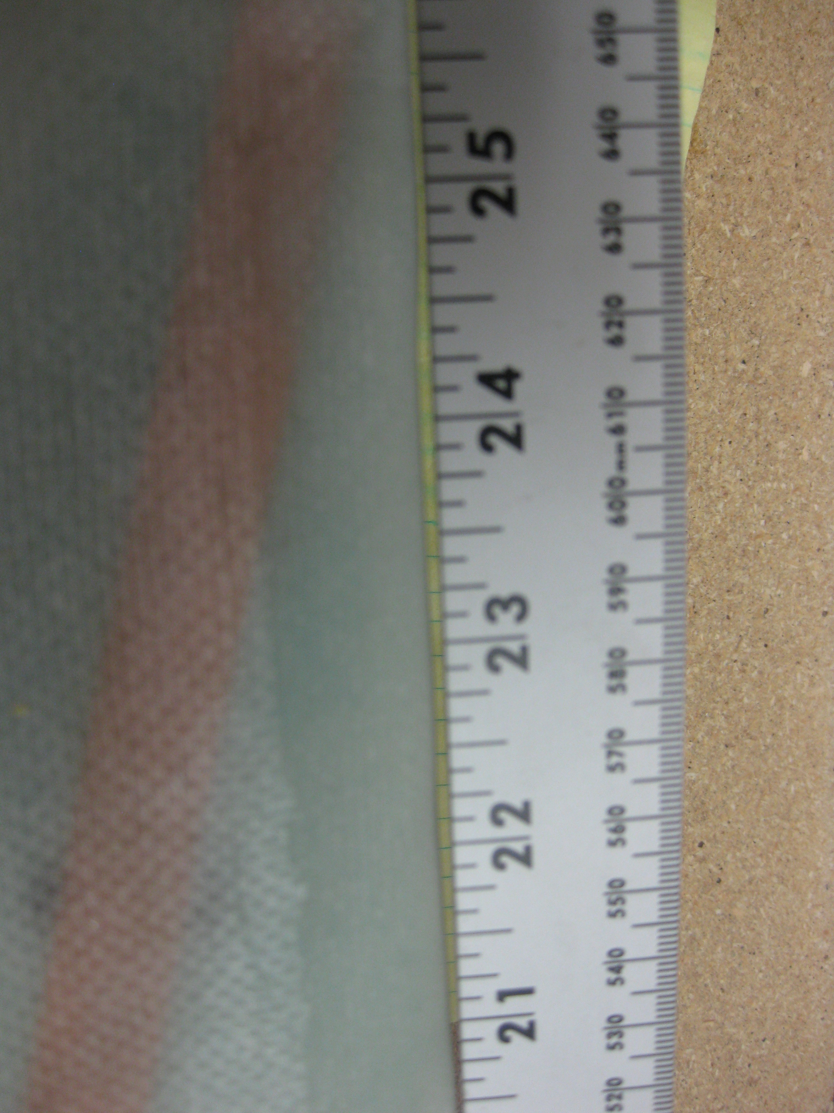
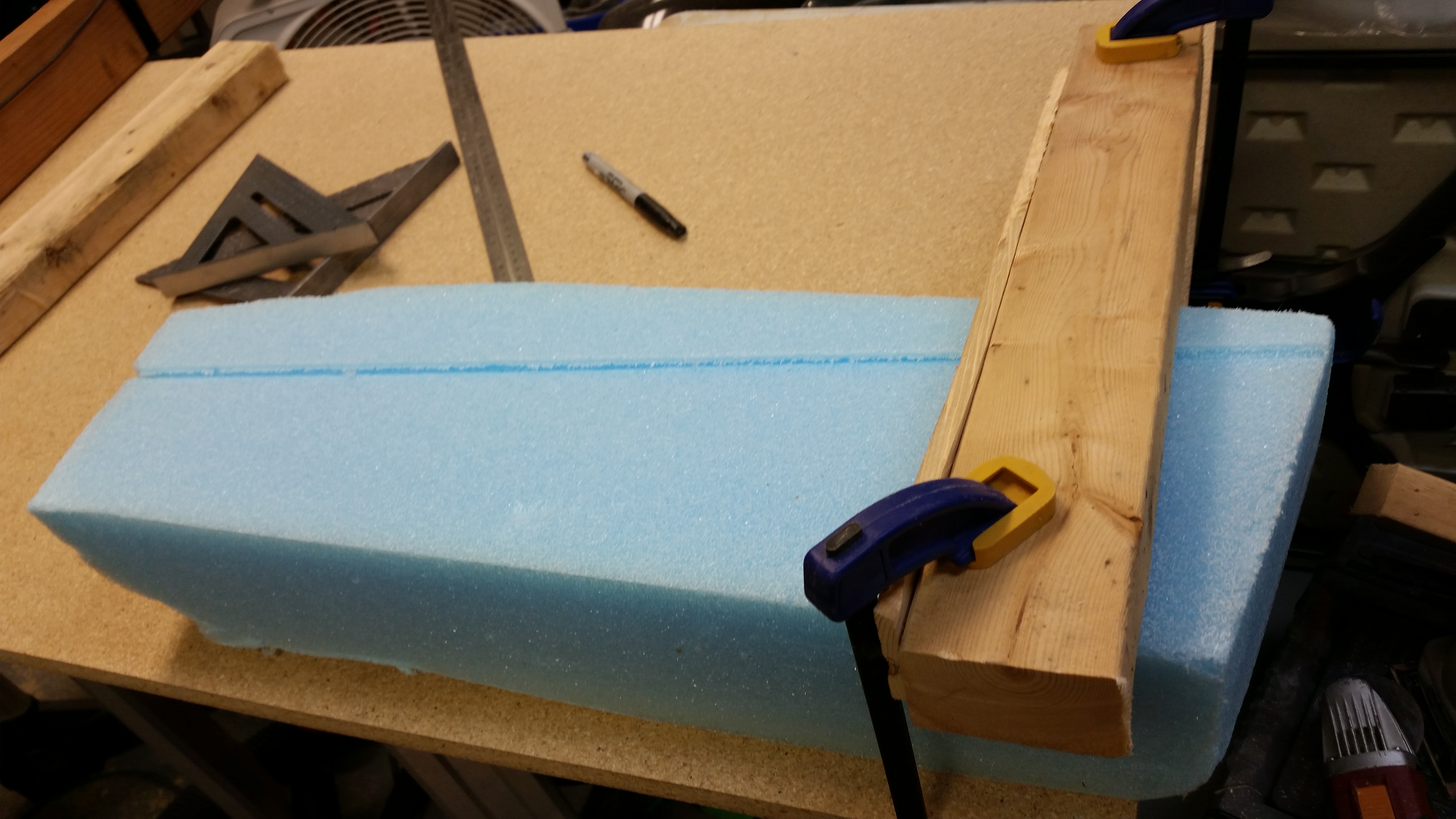
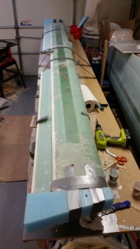
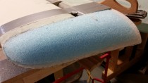
You may have noticed that I had pre-marked the centerline and then went 54″ out in each direction. Obviously, added together the entire length of the middle core of the canard is 108″ total (these pics are of just the middle core so far).
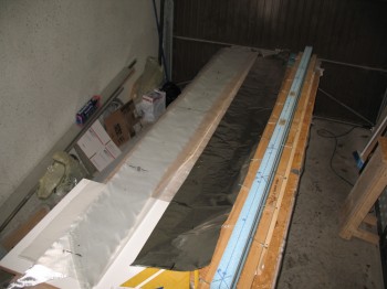
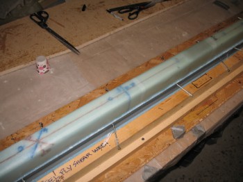
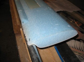
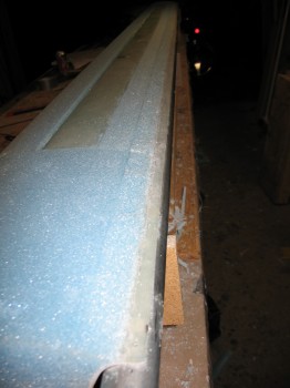
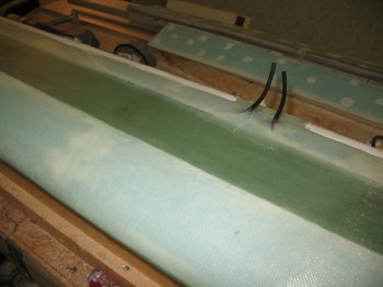
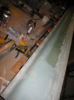
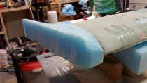
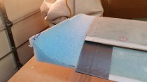
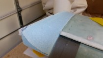
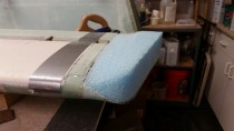
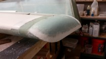
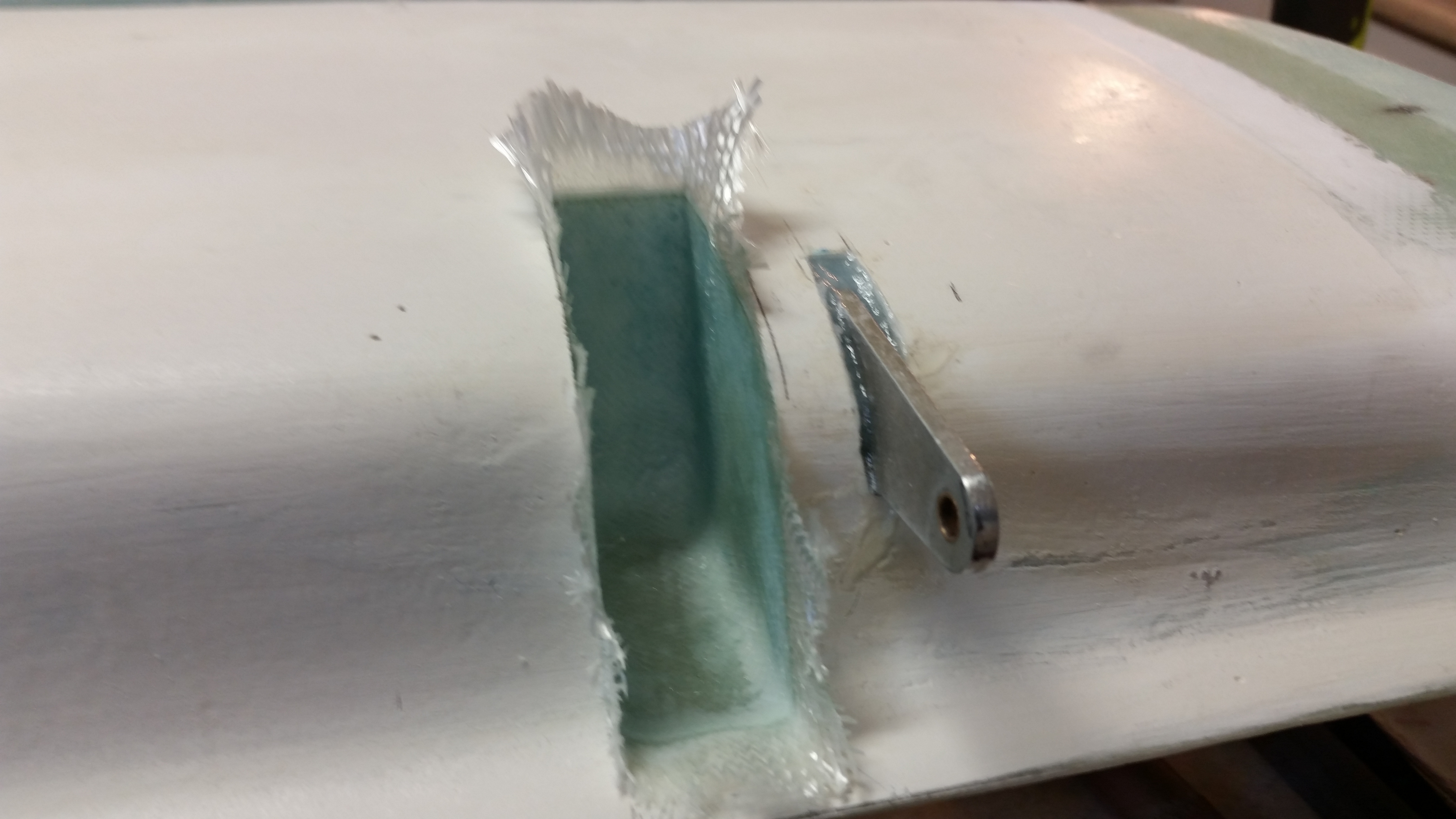
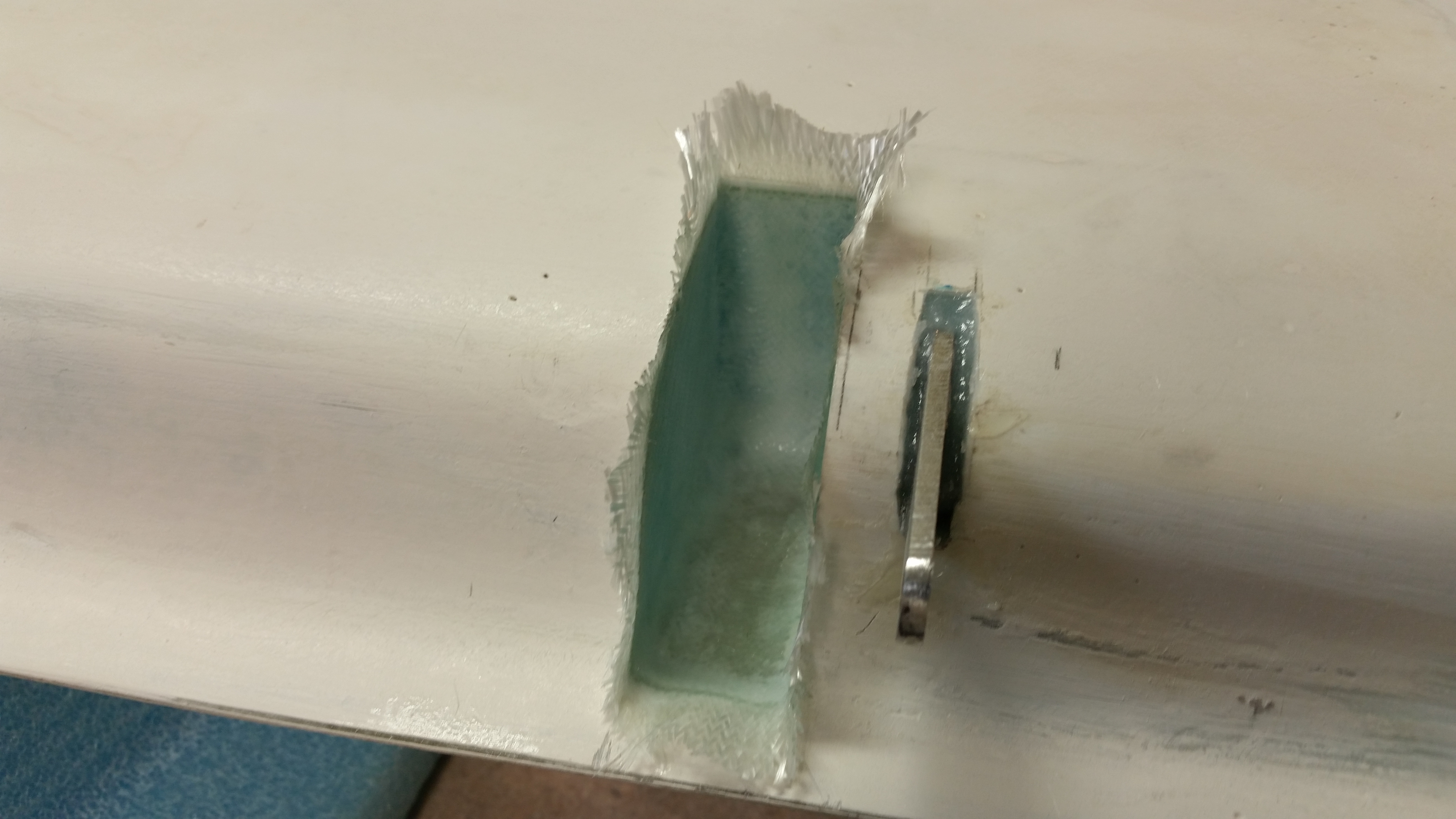
After removing the front rounded nose of the canard from each side I taped up around the bottom lip of the canard (on the aft section of the foam core) for what will be yet another shear web layup (my last on this bird!).
I marked a line down the CL on the top of the shear web. Technically this line is supposed to be at WL 19.4, but I have no idea where that is. And reading what other builders have posted on the forums, neither do they!
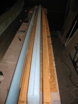
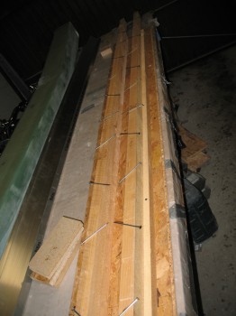
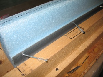
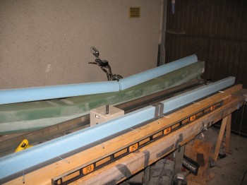
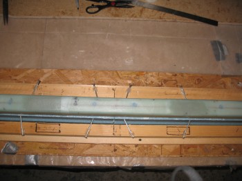
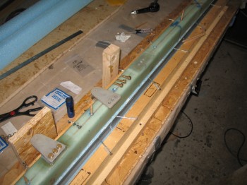
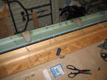
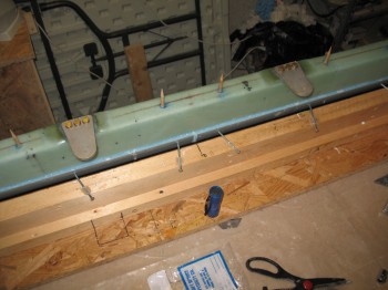
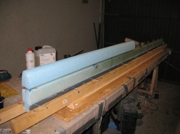
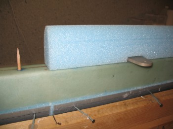
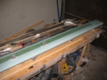
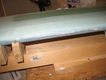
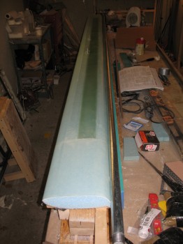
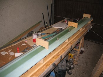
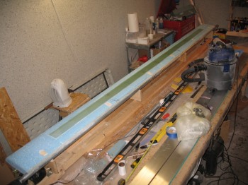
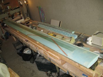
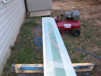
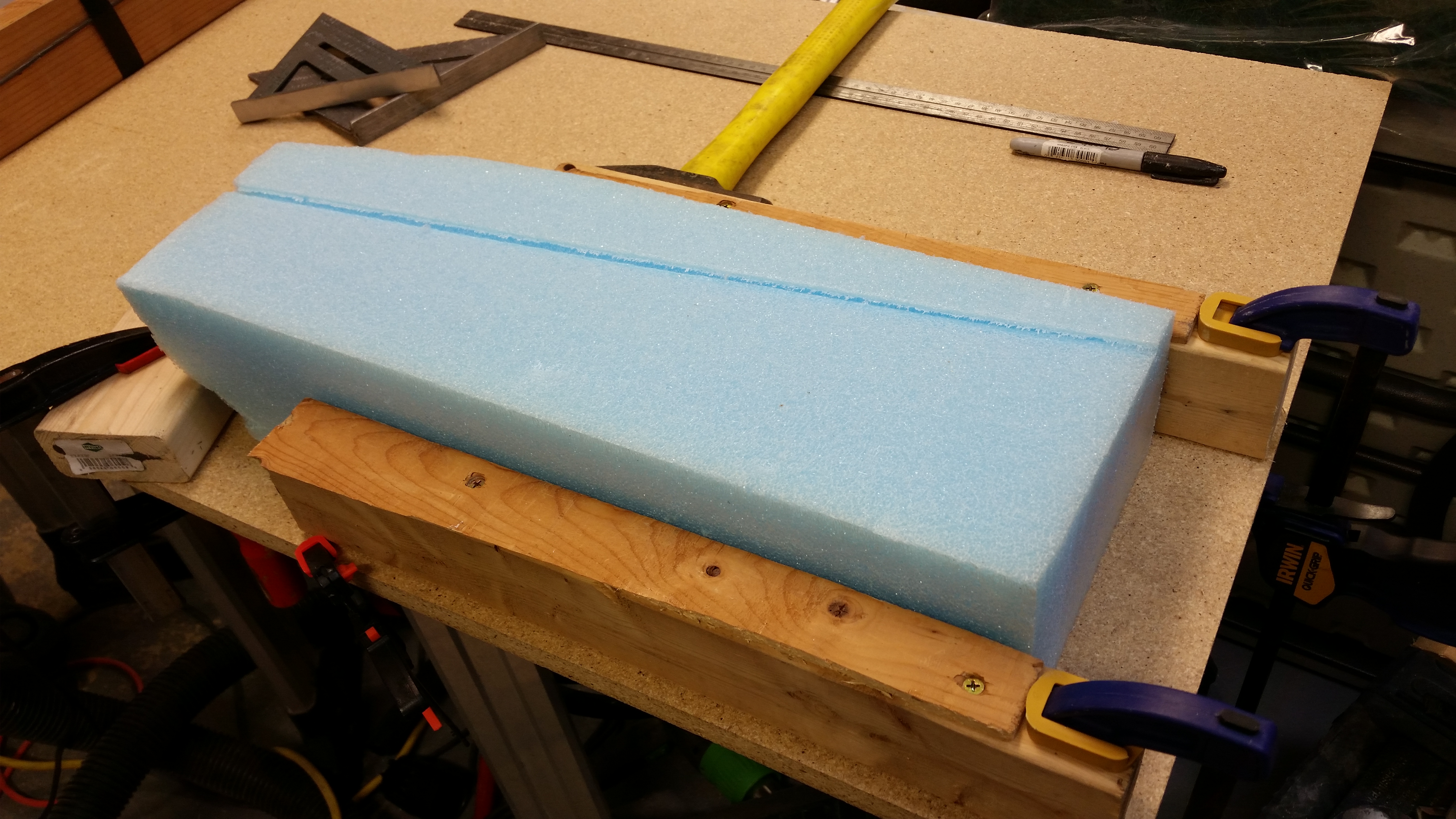
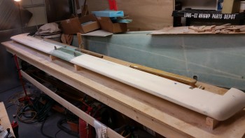
I leveled out the foam canard core to ensure it was straight along the entire top edge and then held it in place with the 4″ nails stuck into the side of the core and into the protective tape . . . just below the edge of the tape (and the edge of the shear web).
I hot glued all the nails to the jig for just one half of the canard foam core.
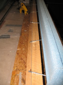
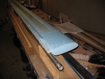
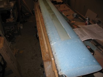
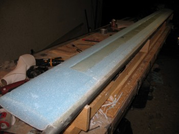
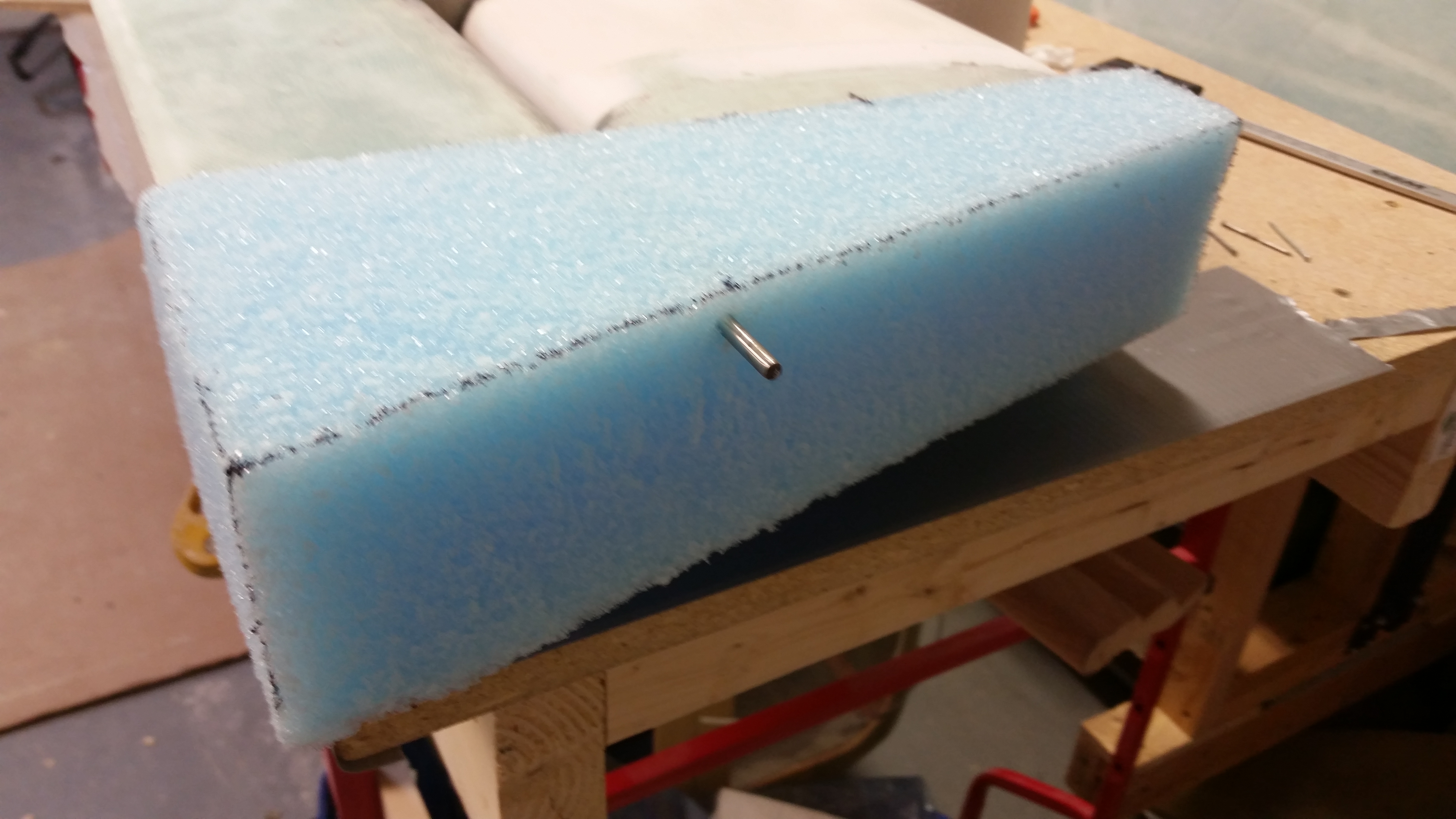
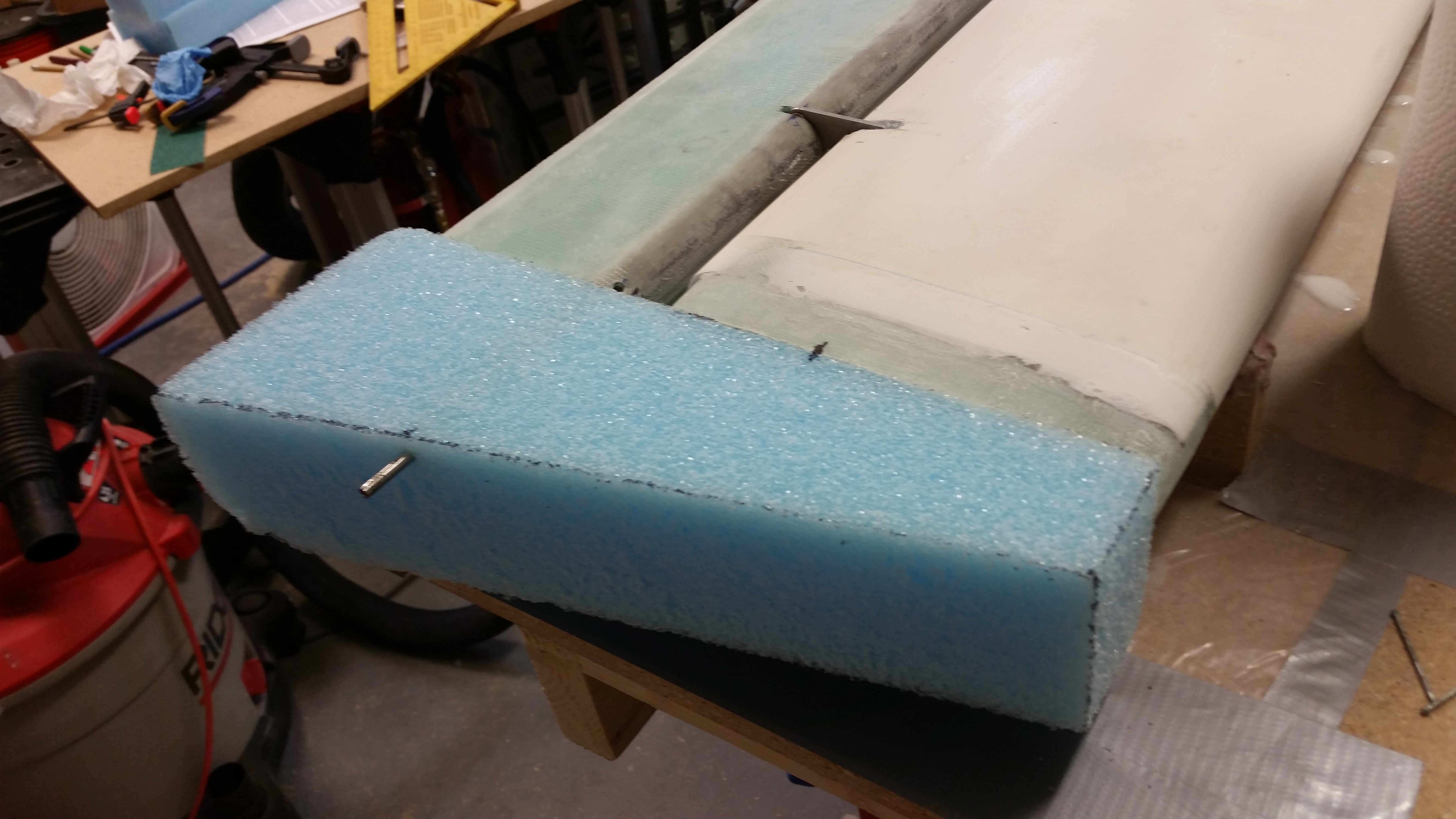
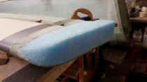
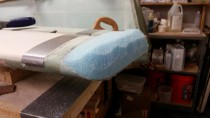
I then whipped up some micro and bonded the 2 foam core sides together. As you can see, this is much more easily accomplished when one of the core halves is held securely in place and immobilized. Once I set the two halves in place (taping along each connecting edge to protect the foam) I then hot glued all the nails in place to the wood jig for the other foam core half.
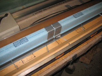
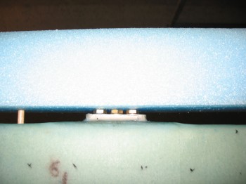
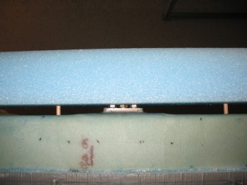
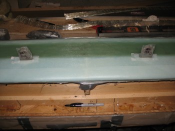
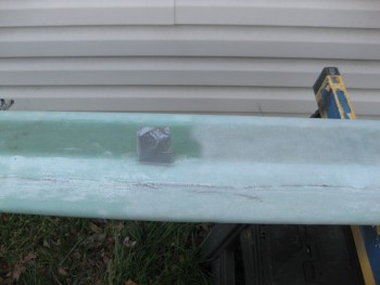
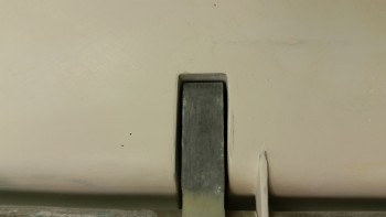
I then marked up the locations of the NCT tab mounts to show where they will be situated (these are the tabs that will hold the canard to the fuselage, at/on bulkhead F22).
Before closing up for the evening I turned the HEATER ON! (This definitely ain’t Tampa!)
•••
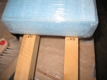
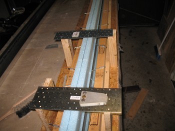
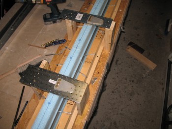
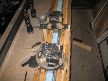
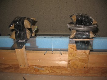
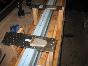
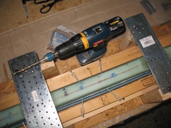
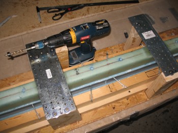
27 April 2013 — I measured some scrap wood & cut 4 pieces for the canard mounting tabs, nutplate mounting supports and then mounted them to the canard jig base.
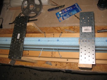
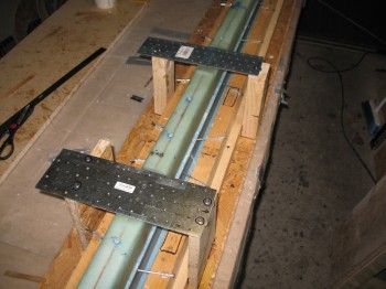
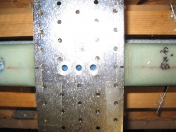
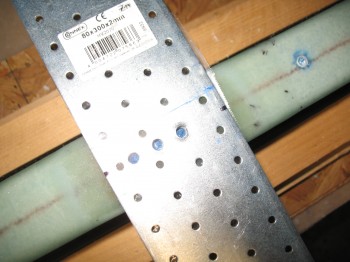
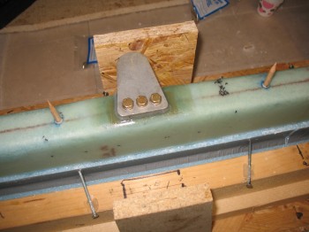
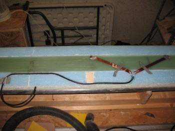
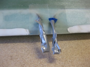
I then took 2 pieces of scrap metal and drilled 3 holes each using one of the NC-CLT mounting tabs as a template (so the 3 holes line up with the 3 bolt holes on the mounting tabs).
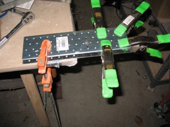
I then mounted the nutplate, canard mounting tab, bolts, and washers to the metal cross plate to mount to the nutplates.
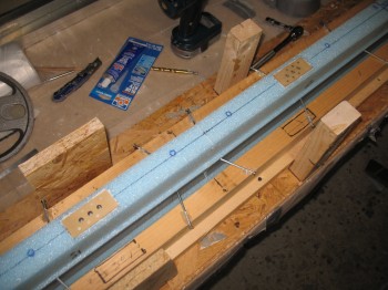
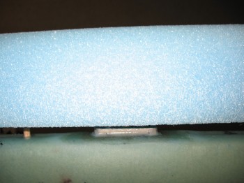
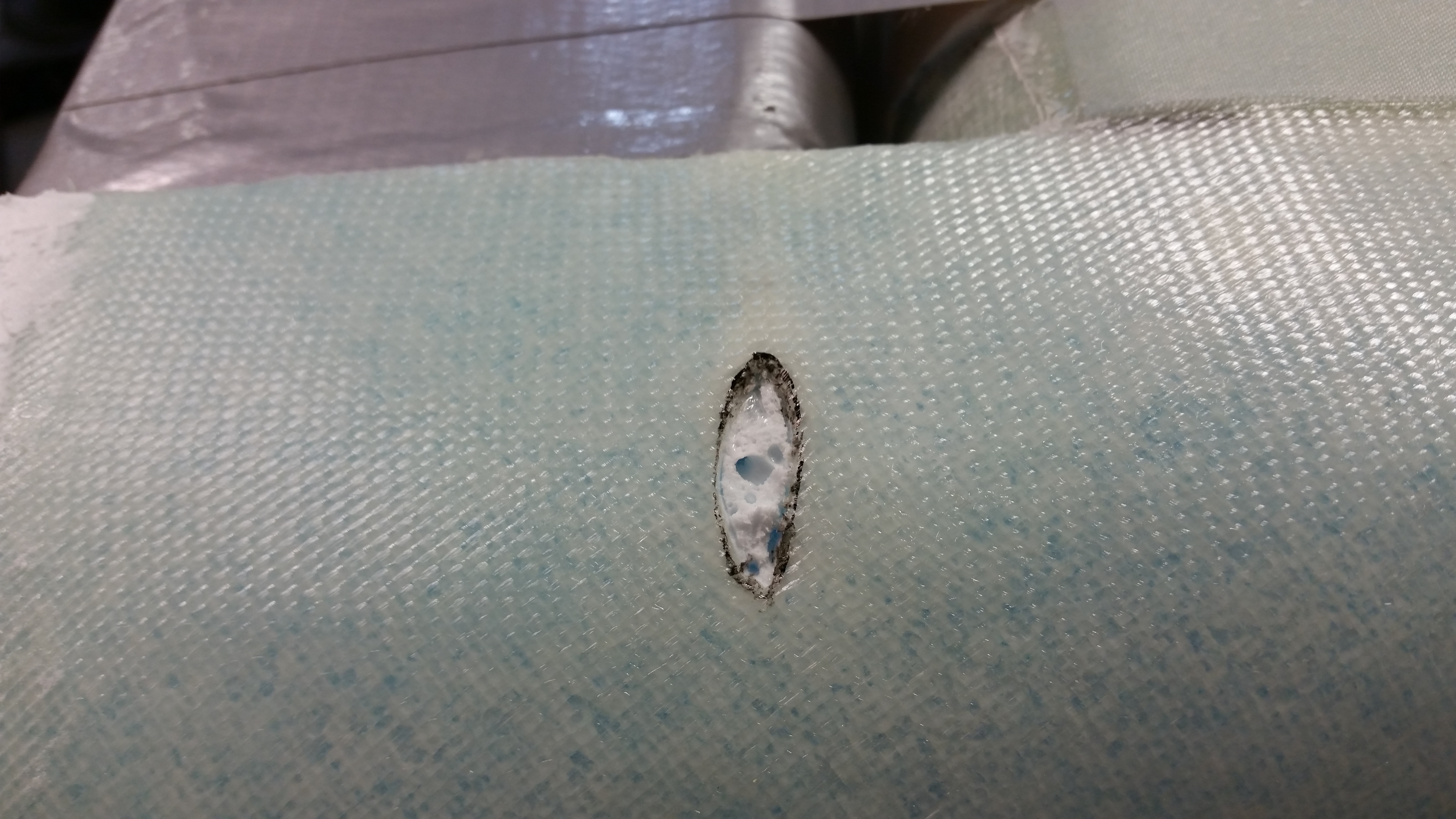
I dug out foam in the canard face so that the mounting tab nutplate would sit flush in the hole. Note: Standard distance from canard CL is BL 6.5, but I went with BL 6.8 because my F22 is about 0.6″ wider than stock (22.2″ vs 21.6″)
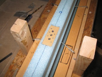
I did a dry run to ensure everything was lining up correctly and that my jig mounting posts were the correct height. It all looked good.
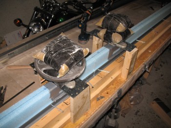
I micro’d in the nutplates (which were mounted to the steel cross templates and the mounting tabs) into the canard foam and then weighed the entire assemble down to ensure the nutplates sat flush with the foam.
After I had everything situated for the mounting tab nutplate install, I went to my downstairs shop and cut the UNI glass for the shear web. I then pre-deployed the shear web to the garage.
After diner I checked the micro left over in the cup. It was still just a tad spongy, and the temp had dropped a little, so I cranked up a couple heaters to warm things up a bit.
•••
28 April 2013 — I started out by checking the cured micro sample in the cup. It looked good.
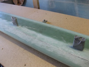
Then I removed the nutplate mounting assemblies.
The nutplate installation into the foam looked good on both sides. I cleaned up the edges a little bit from some micro squeezing out along the edges, but it only took about 5 min to have it all looking spiffy.
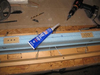
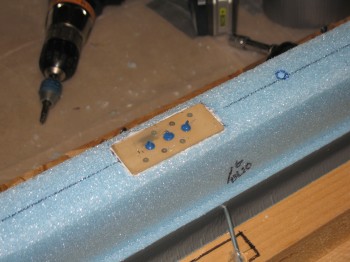
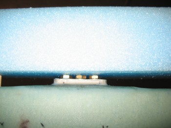
I forget where, but a canard builder had offered a builder’s tip to use Blue RTV to seal the bolt holes so they’d be preserved and no epoxy would get in and seal them up. So I sealed all 6 of the bolt holes in the nutplates with the Blue RTV. It was a little tricky to work with, and once it got on something, it didn’t want to come off.
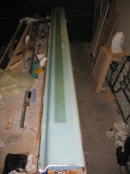
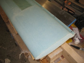
I then grabbed my shear web glass that I cut last night and set it up for a pre-preg layup, just as I had done with the wing shear webs.
I then mixed up some epoxy, wet out the shear web UNI and transferred it over to the aluminum foil. I then transferred the pre-pregged glass to the canard.
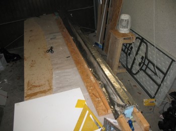
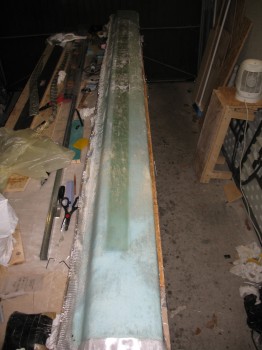
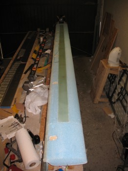
Once I glassed the UNI shear web layup, I dutifully added peel ply as per the stern note I left myself on the canard jig!
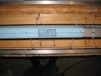
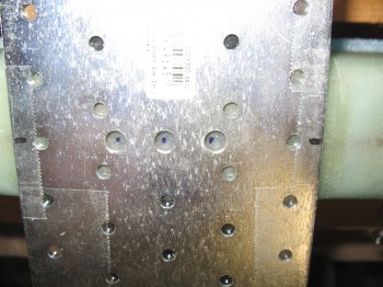
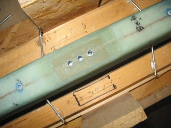
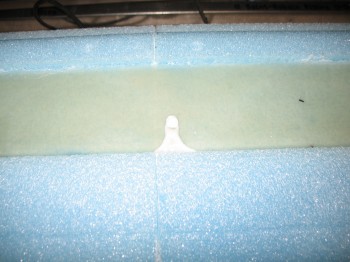
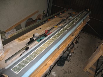
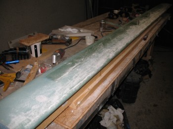
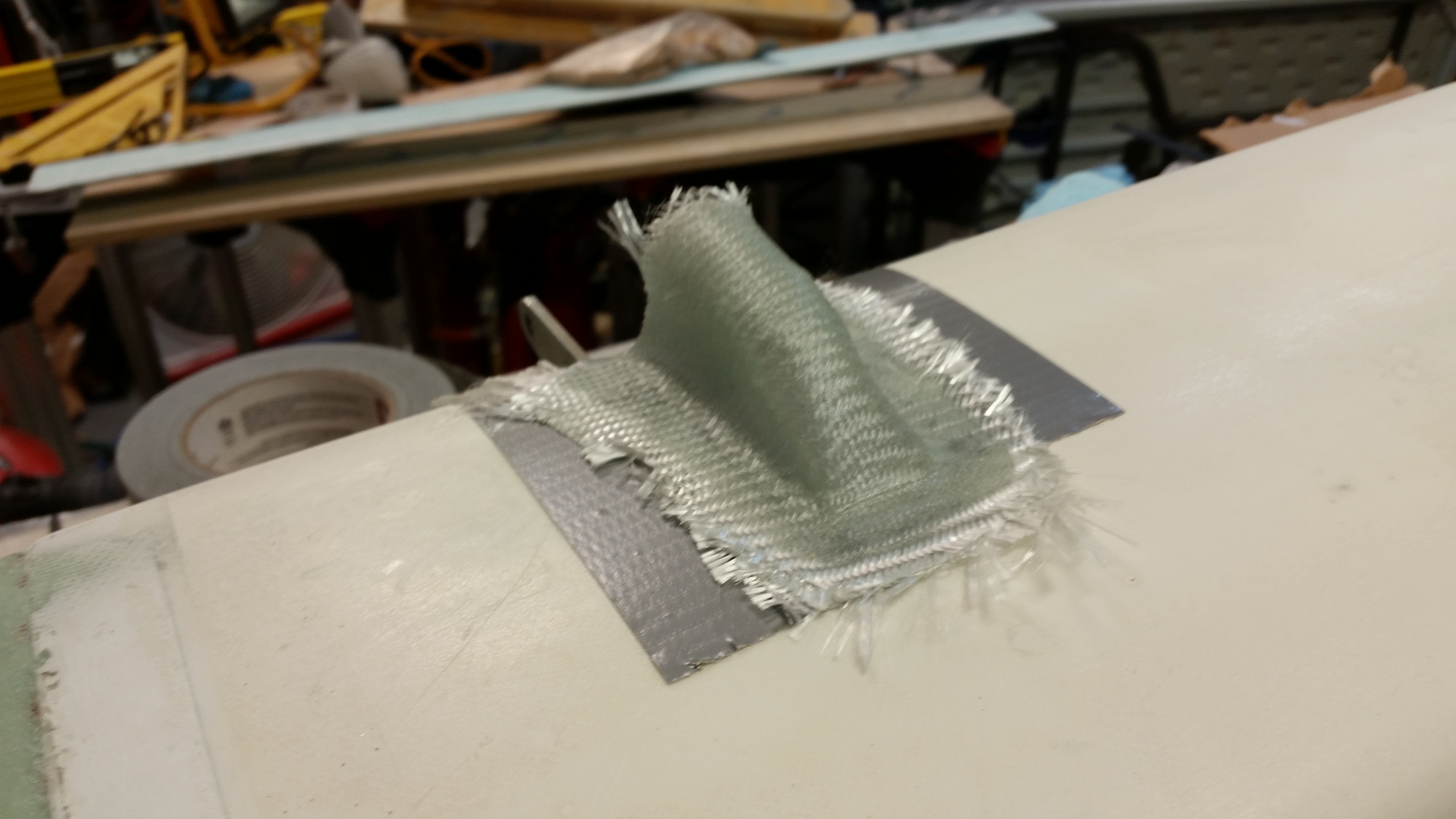
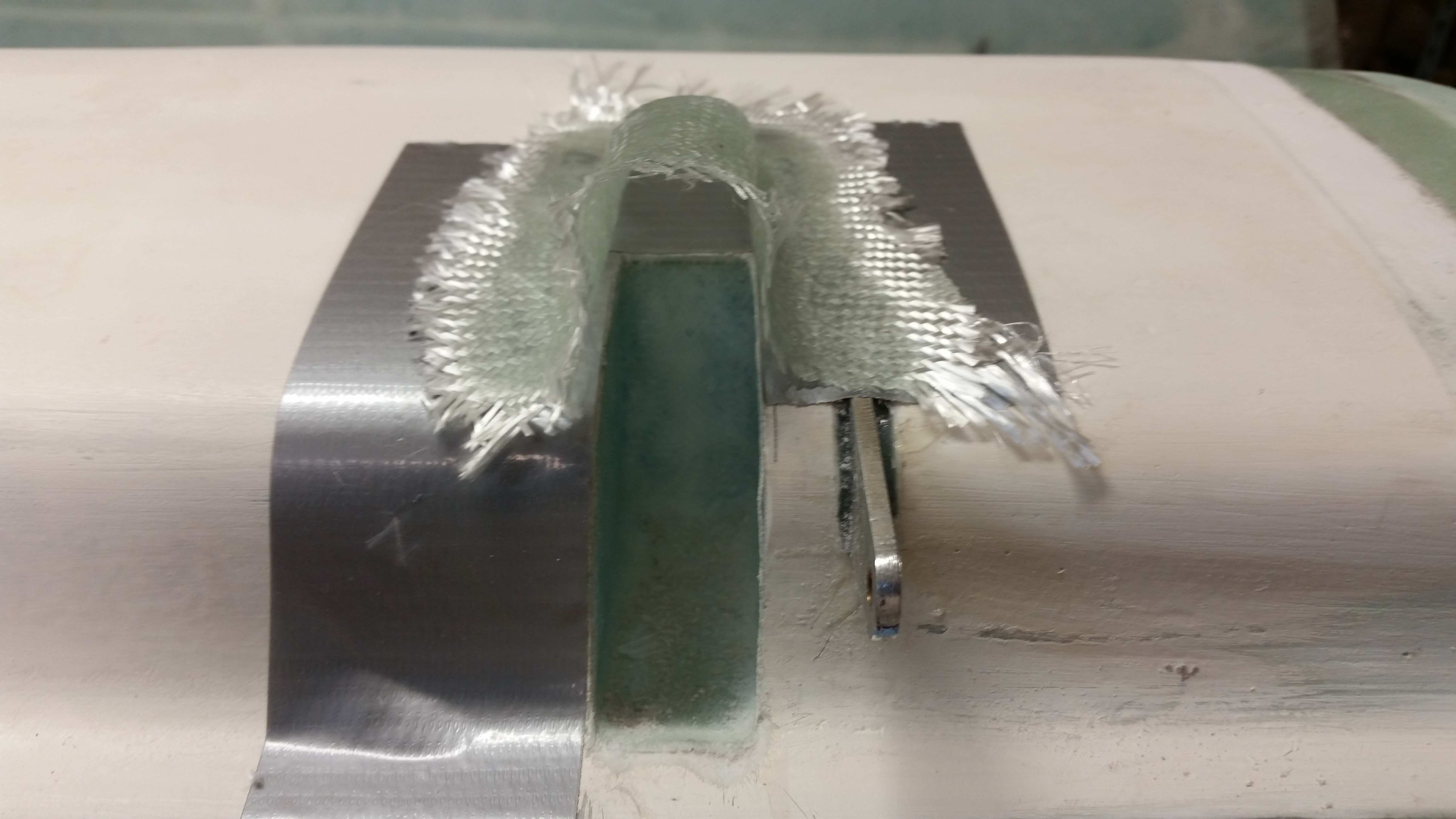
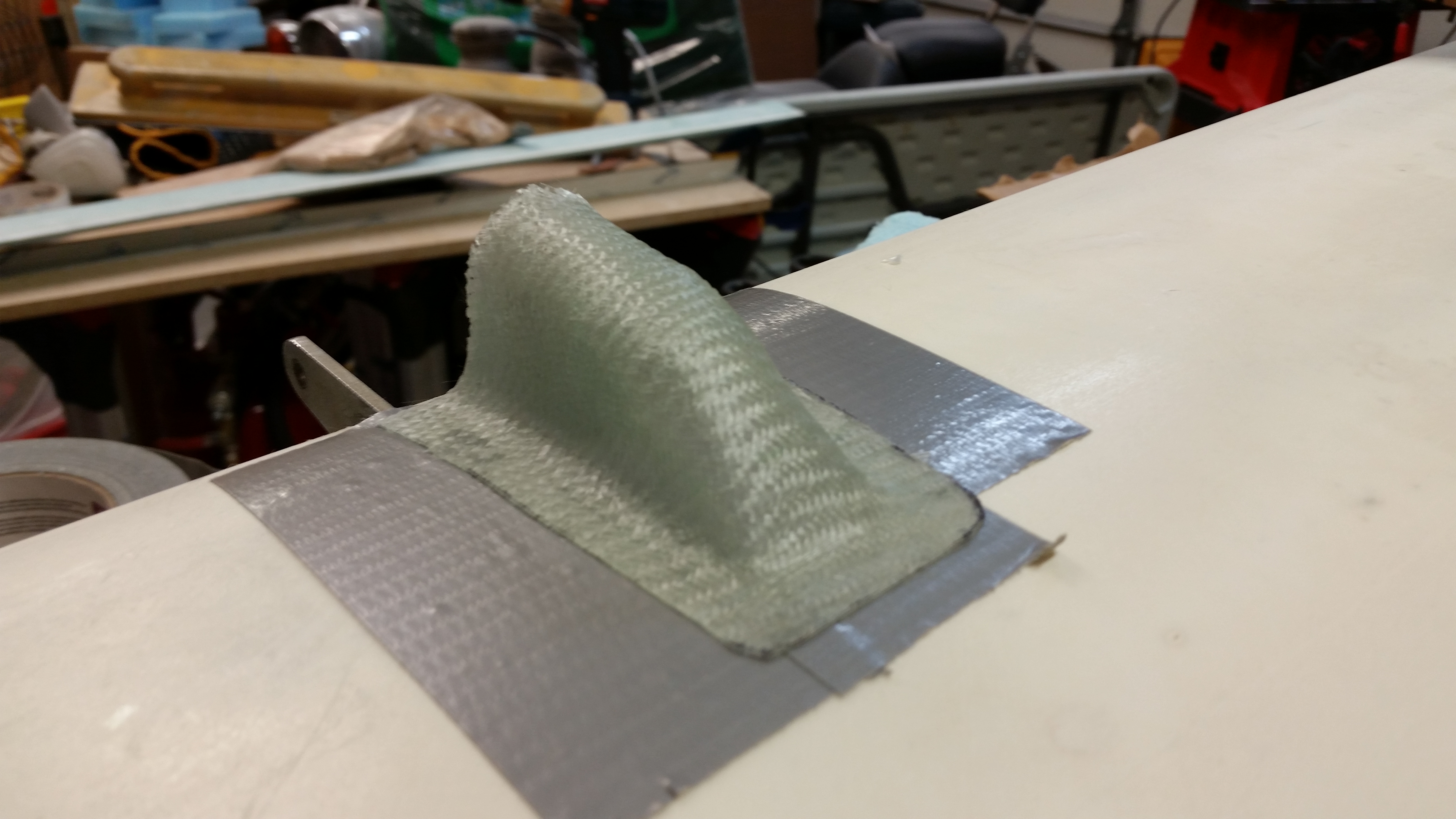
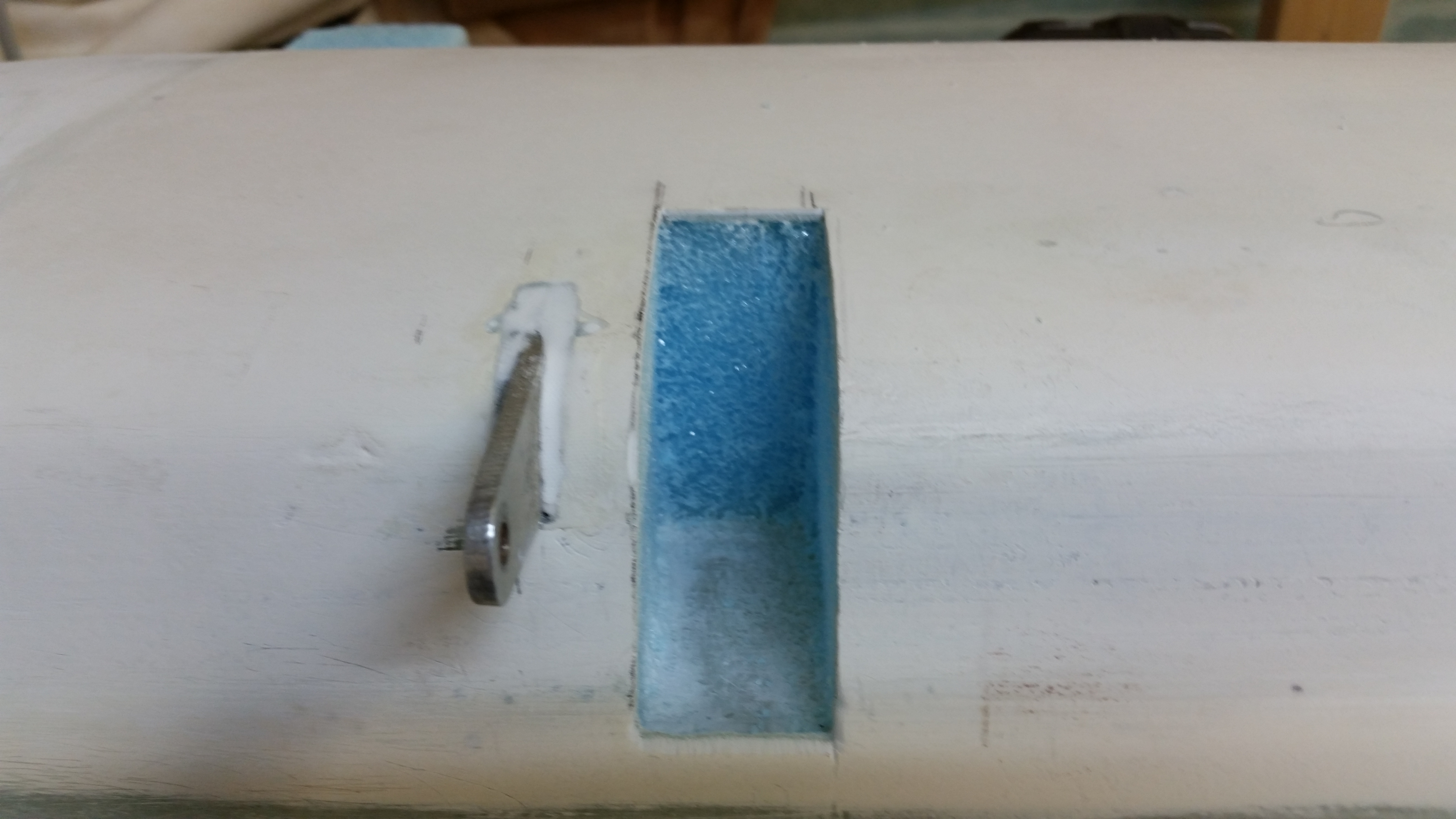
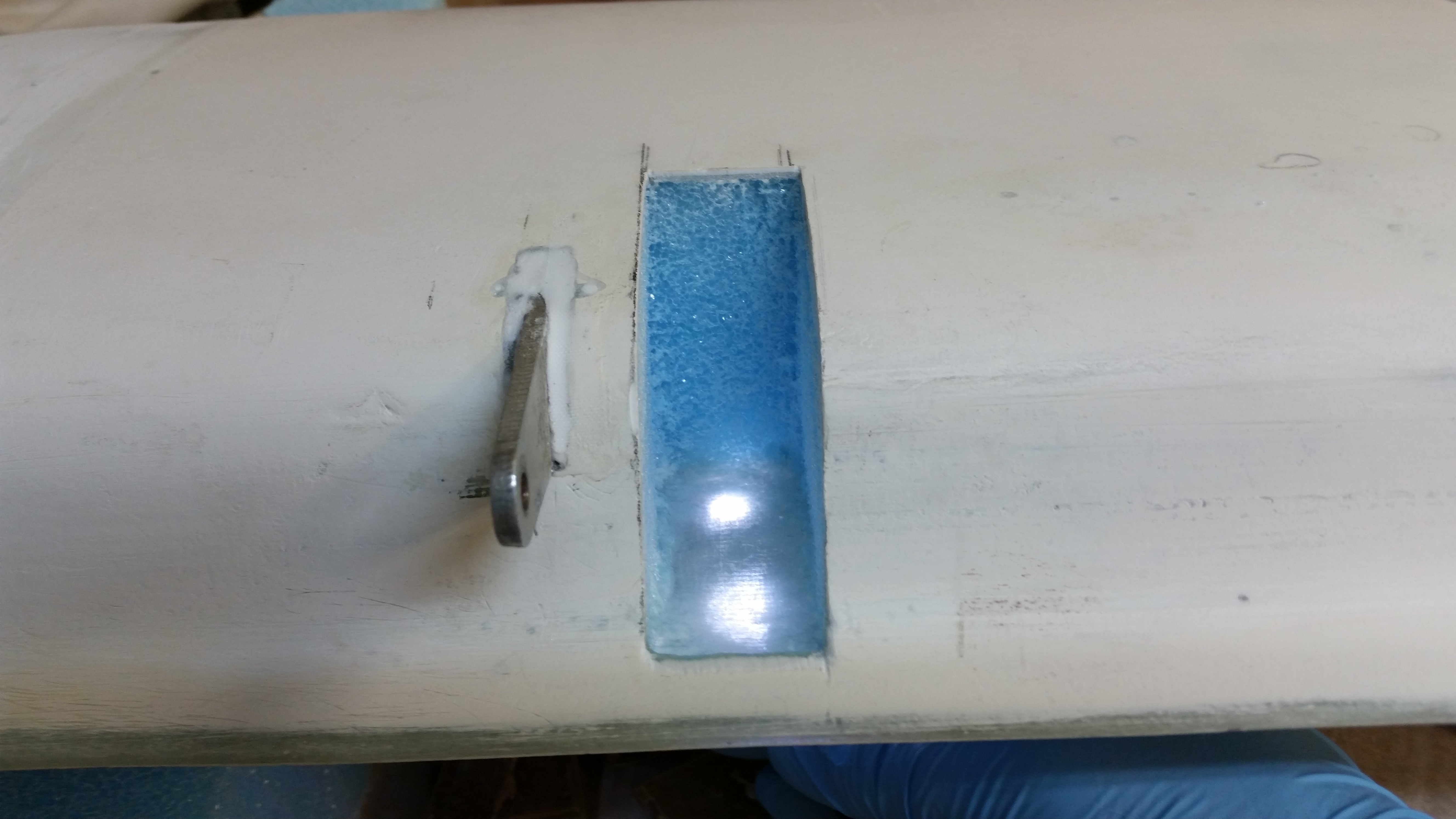
You can see in the picture below that each nutplate is covered with a pad that is made up of 9-plies of 1-1/2″ x 4″ BID covered by a single ply of 4″ x 8″ BID. This makes for stout hard points to mount the canard mounting tabs to. The plans call for using micro around the edges of the 9-ply BID pad as somewhat of a fillet for the top 1-ply piece of BID. I cheated a little and used flox for a little more oomph (Call me chicken, but this is one area that I don’t want to be weak in any way).
Finally, I used the Dritz electric scissors to trim the glass along the ends and along the edge of the spar cap channel.
•••
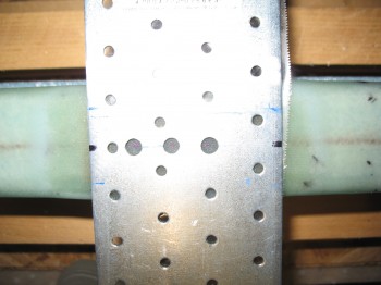
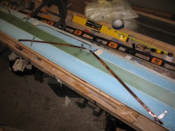
29 April 2013 — I started out today by drilling a 1/4″ hole at each marked spot on the top/front of the canard (in the present configuration) for the 12 each 1/4″ sharpened wood dowels that will align the front part of the canard (or “nose” or LE) to the shear web section of the canard. This is exactly the same process as the main wings, only on a smaller scale. Of course the wings don’t use the wood dowels to line up the front part of the wing to the shear web (unfortunately … seams to be much easier).
I then reinstalled the metal mounting tab jigs & their wood supports, set up a stop on my 1/4″ drill bit and drilled the 6 bolt holes for the canard mounting tabs (NC-CLT) into the ~12 plies of glass over each nutplate.
Then came the real job . . . cleaning the Blue RTV out of the holes in the nutplates. It was probably something akin to a cartoon in how the Blue RTV just did not want to be extricated from those bolt holes. Needless to say, it took A WHILE to get all that rubbery, stubborn Blue RTV out of those holes. My best tools in doing this were my scribe and a cheap set of dental picks I picked up from Harbor Freight.
After finally getting all the Blue RTV out of the bolt holes, I mixed up some flox and attached the canard mounting tabs onto the shear web permanently.
As I quite often do, I mixed up a little bit too much flox, so I used it to mount the 12 sharpened 1/4″ dowels into their holes.
After I got both of the canard mounting tabs installed, along with all the 1/4″ alignment dowels set into place, I took a break and ran to Stuttgart to pick up some more MGS 285 epoxy and slow hardener (Stuttgart is almost 2 hours away).
Now that I was reloaded on epoxy and hardener, and my canard mounting tabs & alignment dowels were cured, I set forth to attach the front leading edge (LE) of the canard.
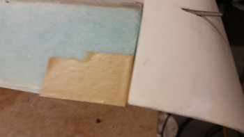
First up on the order of battle was to notch the LE edge foam pieces at the mounting tab locations so they could fit around the mounting tab and also lie flat on the shear web surface. As with many things in this build, it was a trial & error endeavor of taking a little foam out, then setting the foam LE back on, trimming a bit more foam, testing the fit, etc. Although the process may be a bit tedious, it really didn’t take that long… maybe 15 min for each side.
Of course this is where the alignment dowels play a huge role. I can see where trying to do this without the dowels–which weren’t used as per plans in the original Chapter 10–could be a lot more difficult, because it’s not about just getting the foam cut out for the mounting tab, but aligning the front canard foam piece correctly front & back (technically top-to-bottom), and the Outboard & Center alignments correct as well. The dowels made it very EZ to just slip the second half of the canard LE foam into place and have a nice flush fit at the CL between the two canard LE foam cores.
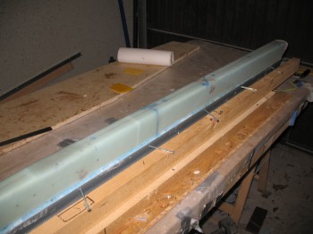
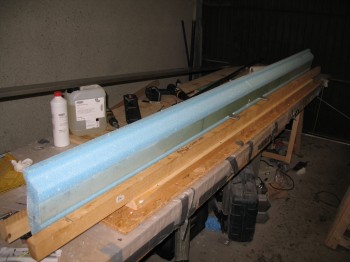
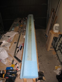
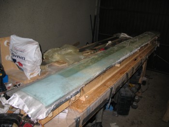
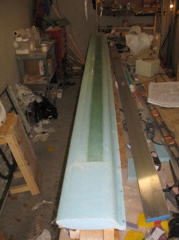
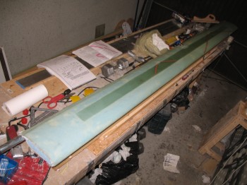
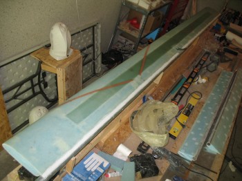
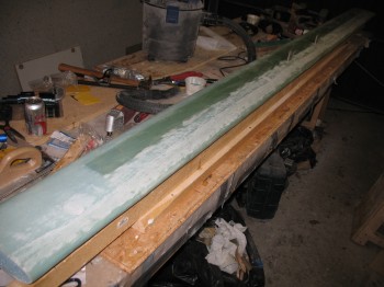
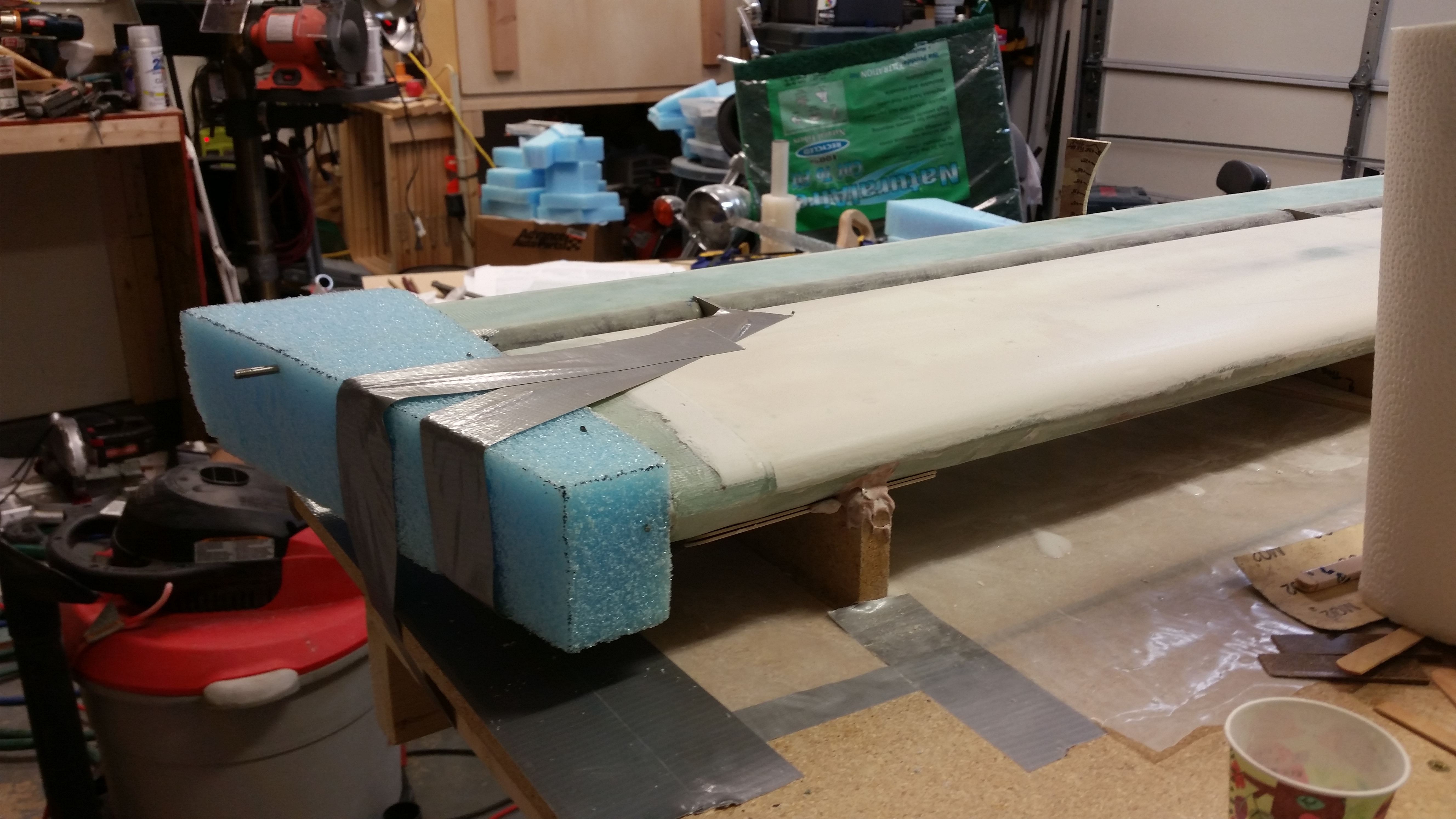
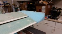
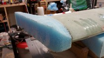
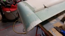
Once I got the notches set for the mounting tabs, and was sure the LE cores were aligned properly, I micro’d both foam LE cores into place. As you can see, I used a fair amount of duct tape to ensure the LE cores had some decent pressure as they cured.
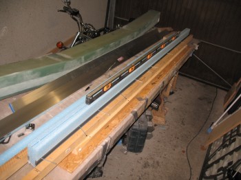
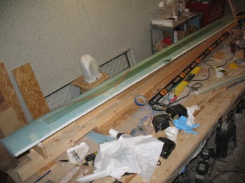
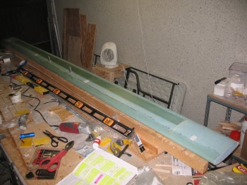
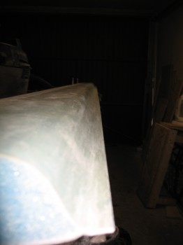
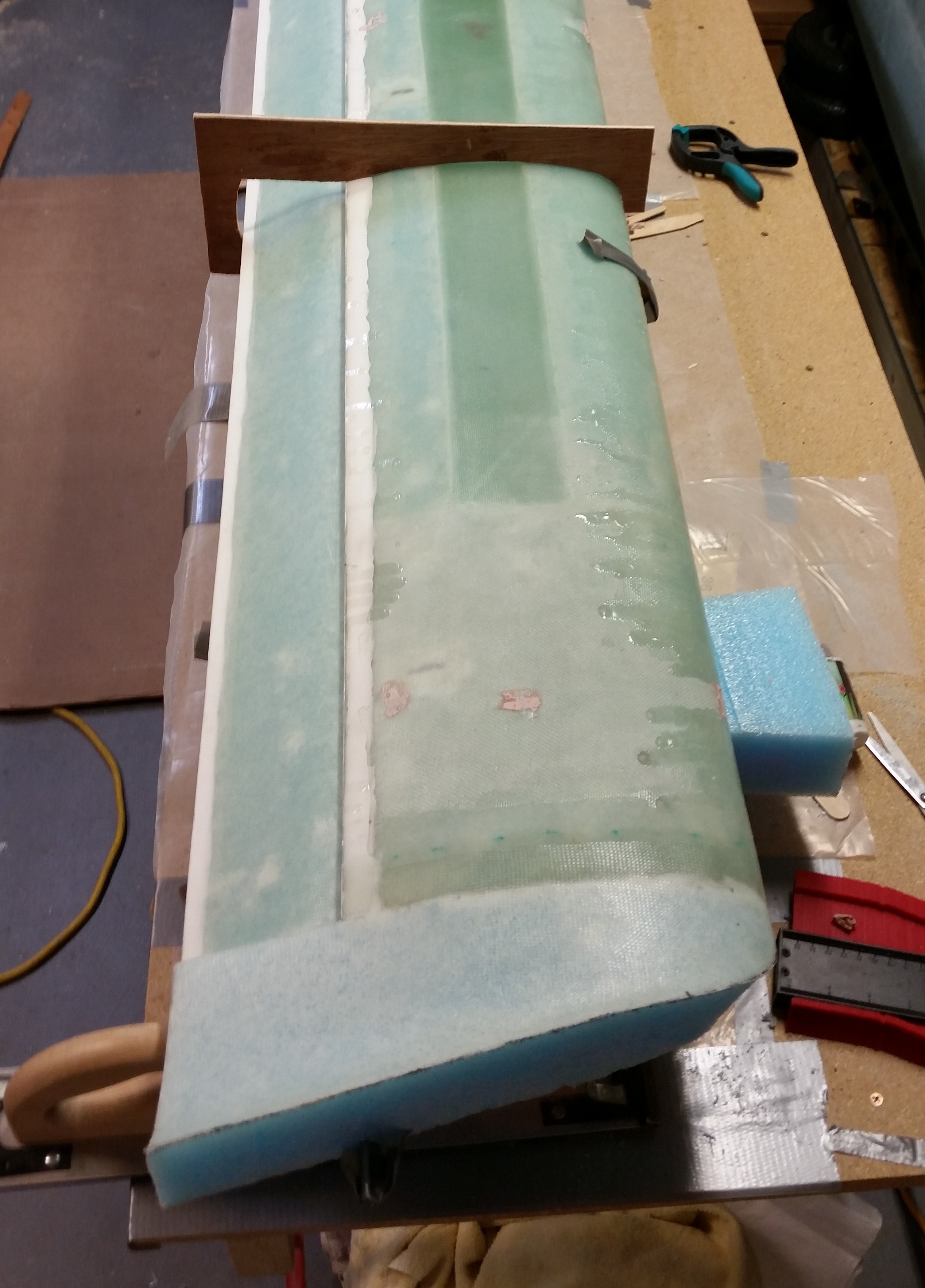
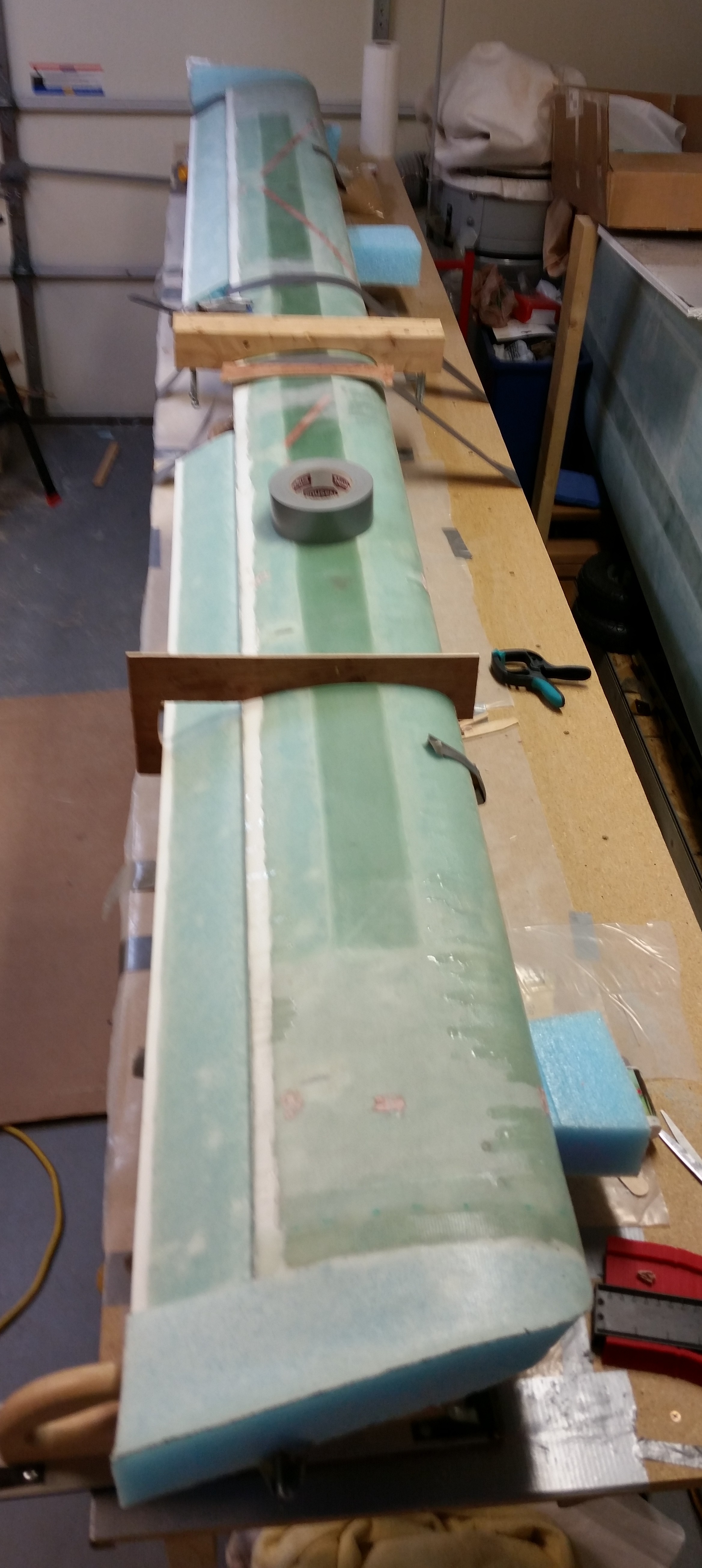
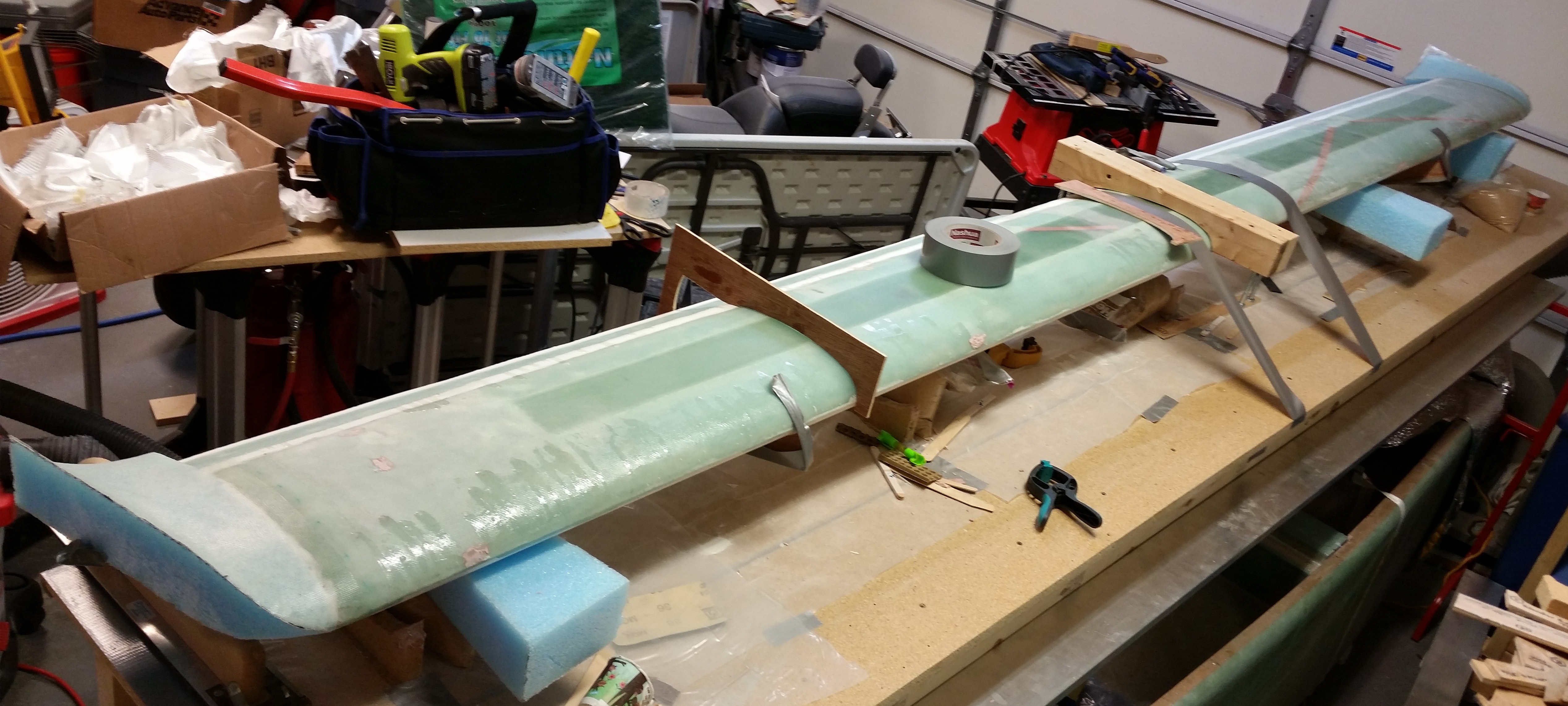
I checked to ensure the canard LE was straight. I was using both my 6′ long level & my new long aluminum straight “board” that I picked up from Praktiker, when I realized I could place the aluminum straight board on the top of the LE without damaging it, which added a little bit more weight and when taped at equidistant points helped to ensure the LE stayed straight.
•••
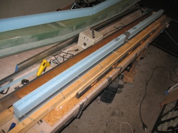
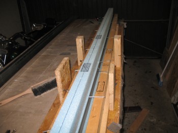
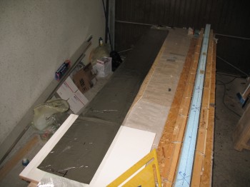
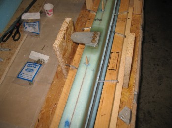
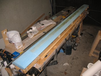
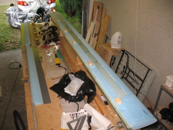
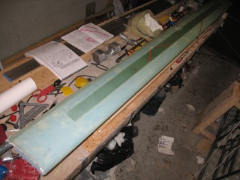
30 April 2013 — I started today by removing the canard from the jig. I then cleaned up the jig & extended it from 108″ to 126″.
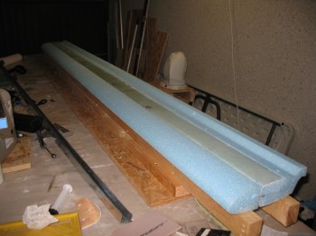
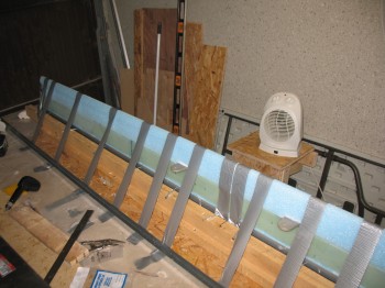
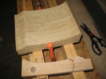
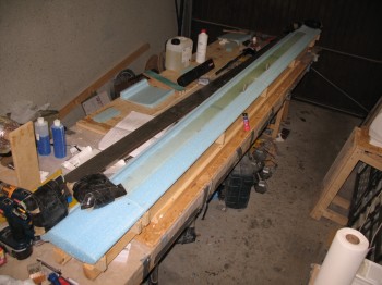
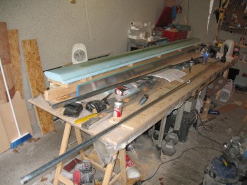
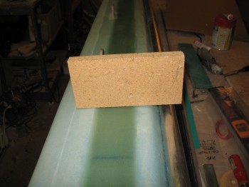
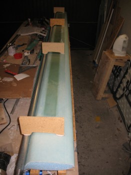
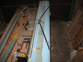
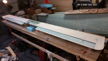
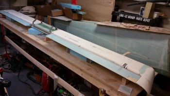
I then cleaned up & sanded the 9 each K-jigs, which will spaced out as per the Roncz canard (not Chap 10) plans to support the canard as it’s upside down getting glassed–which is the next step.
As you can see, I clamped the K-jigs together and sanded them as one piece so they would be the same shape all the way down the row. This will remove nearly all the inconsistencies in the cuts since I had to cut each one individually on the band saw.
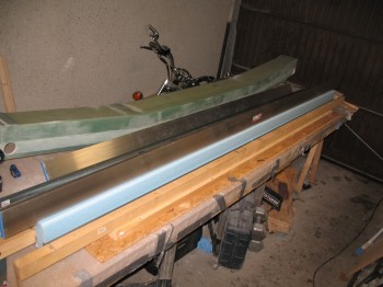
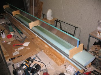
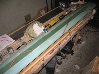
I then mounted the K-jigs to the canard jig base using a hot glue gun. I used a string & my aluminum straight board to ensure they were all straight & level.
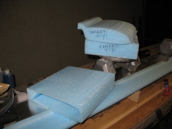
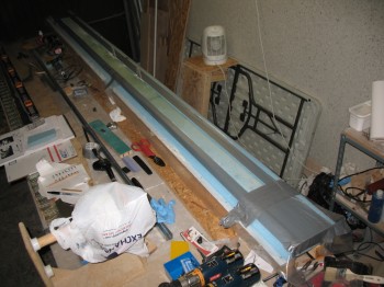
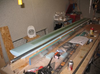
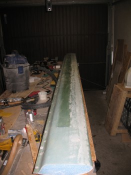
In the pic below there appears to be 2 extra K-jigs mounted to the end of the jig base, but those are there in preparation for the 11 inch canard tips that will get bonded to the end of the current canard structure. Actually, the 11″ tips are more like extensions, because the actual TIPS of the canard will be shaped & glassed into place (with the ends flaring up) after the elevators are mounted.
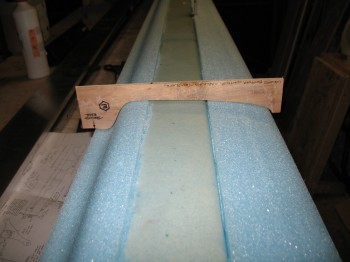
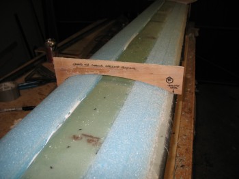
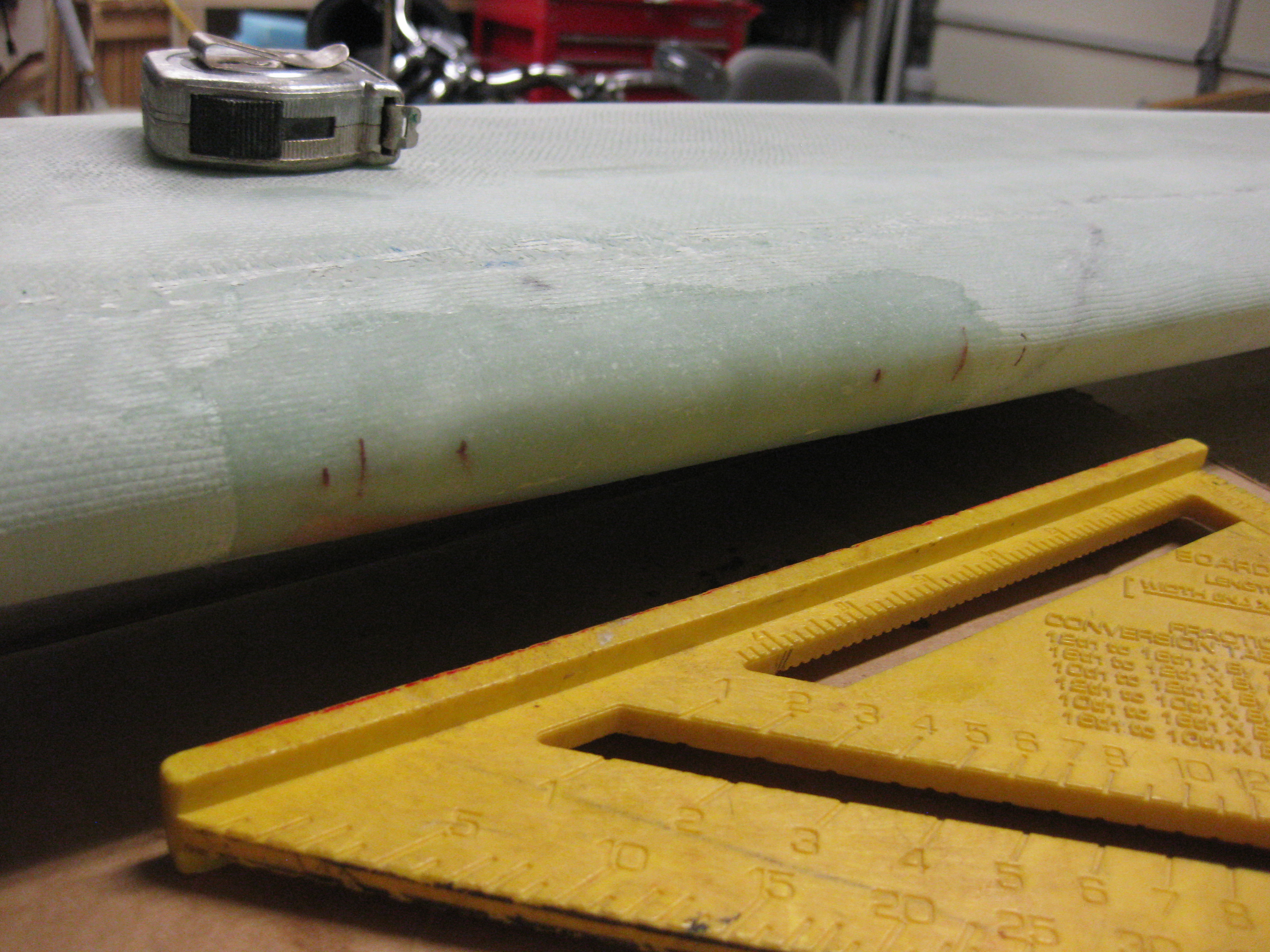
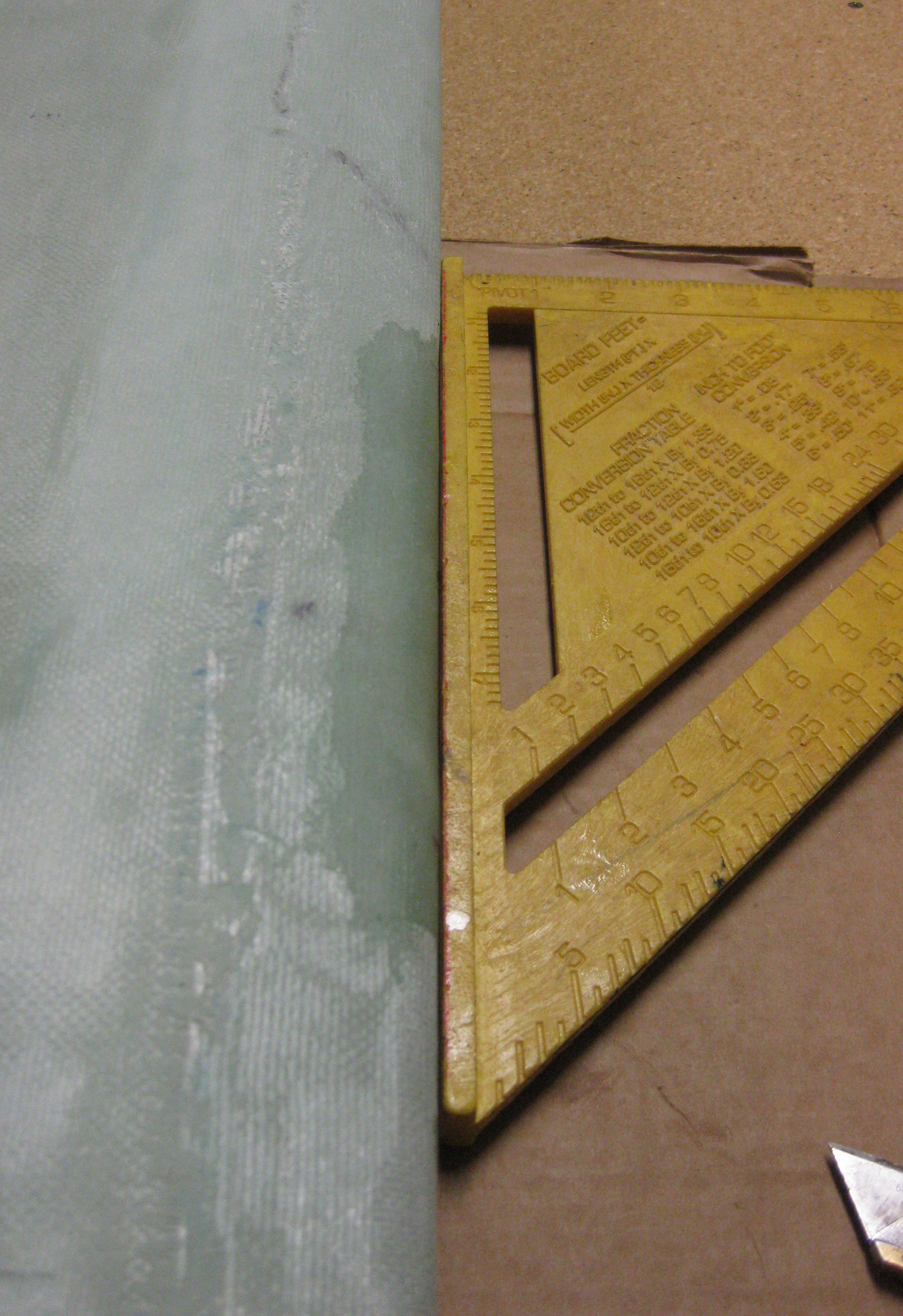
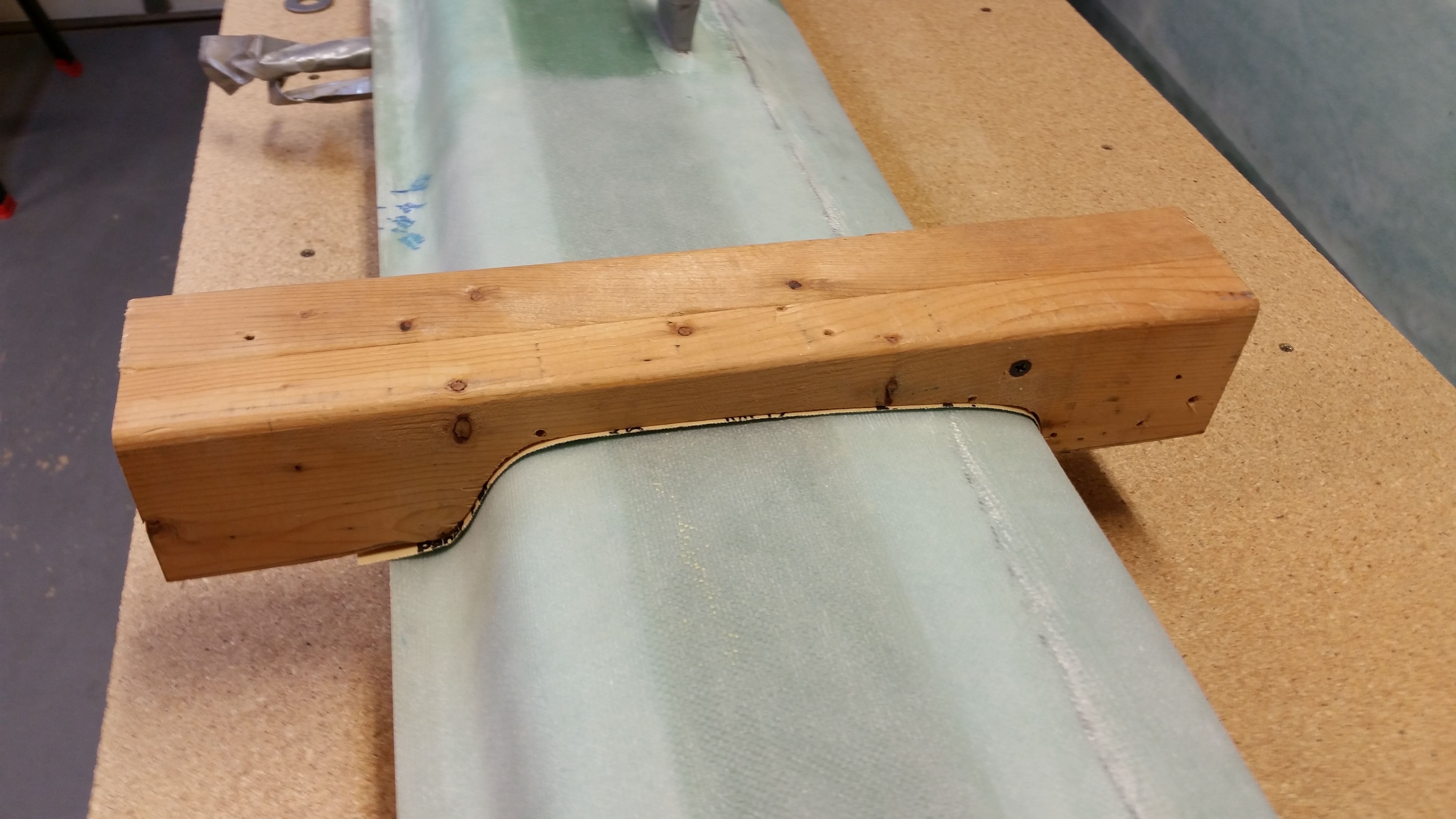
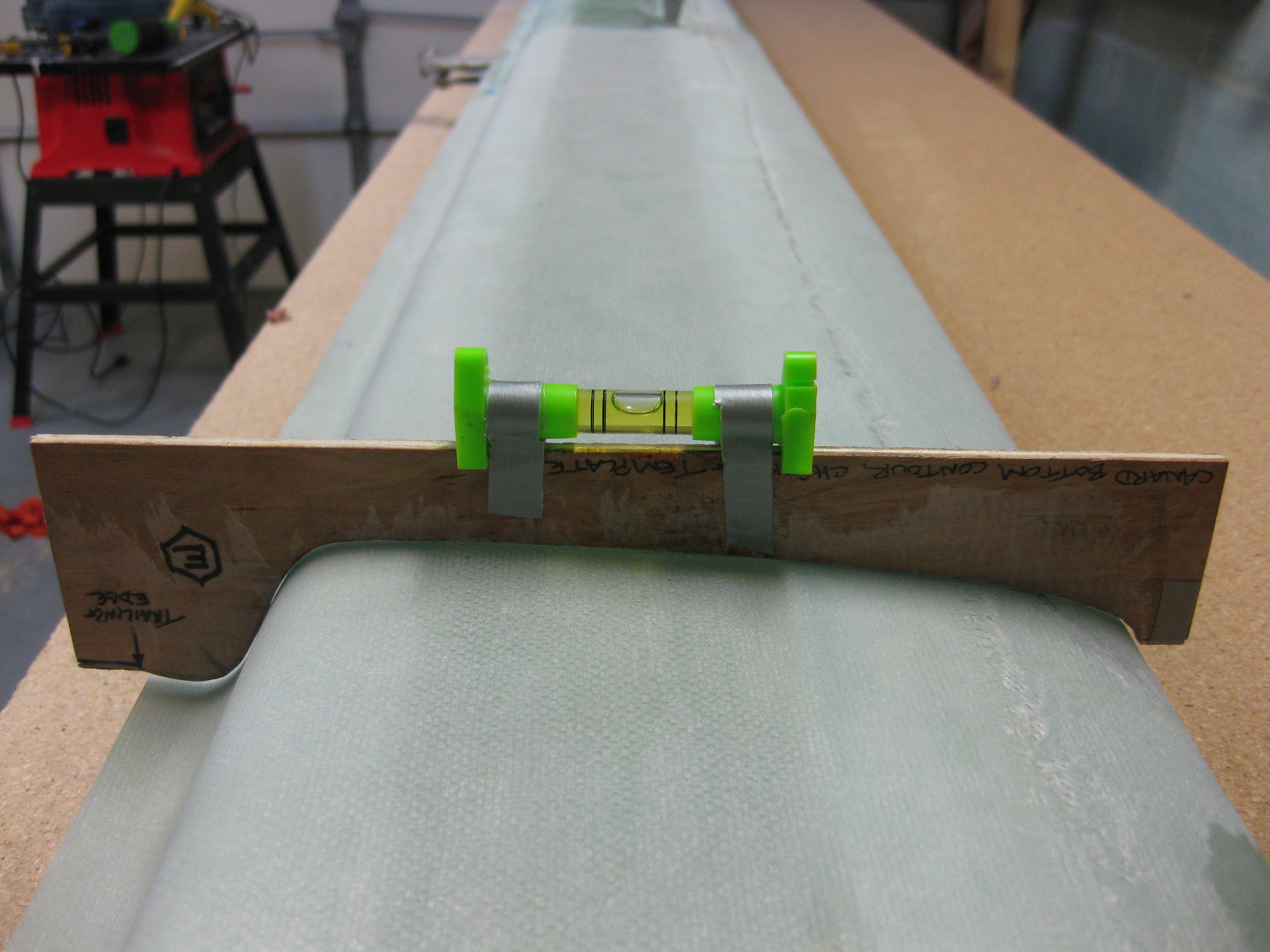
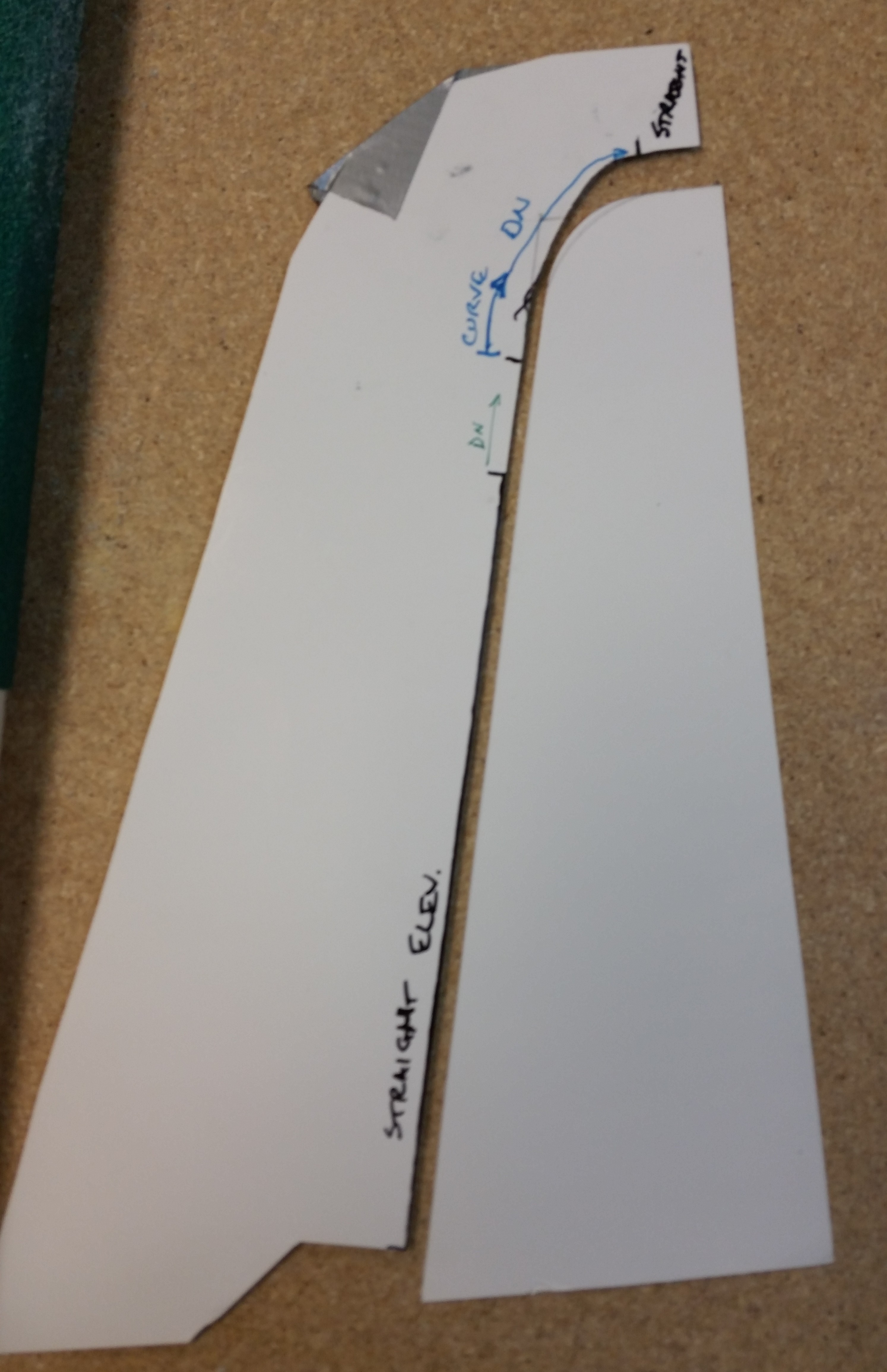
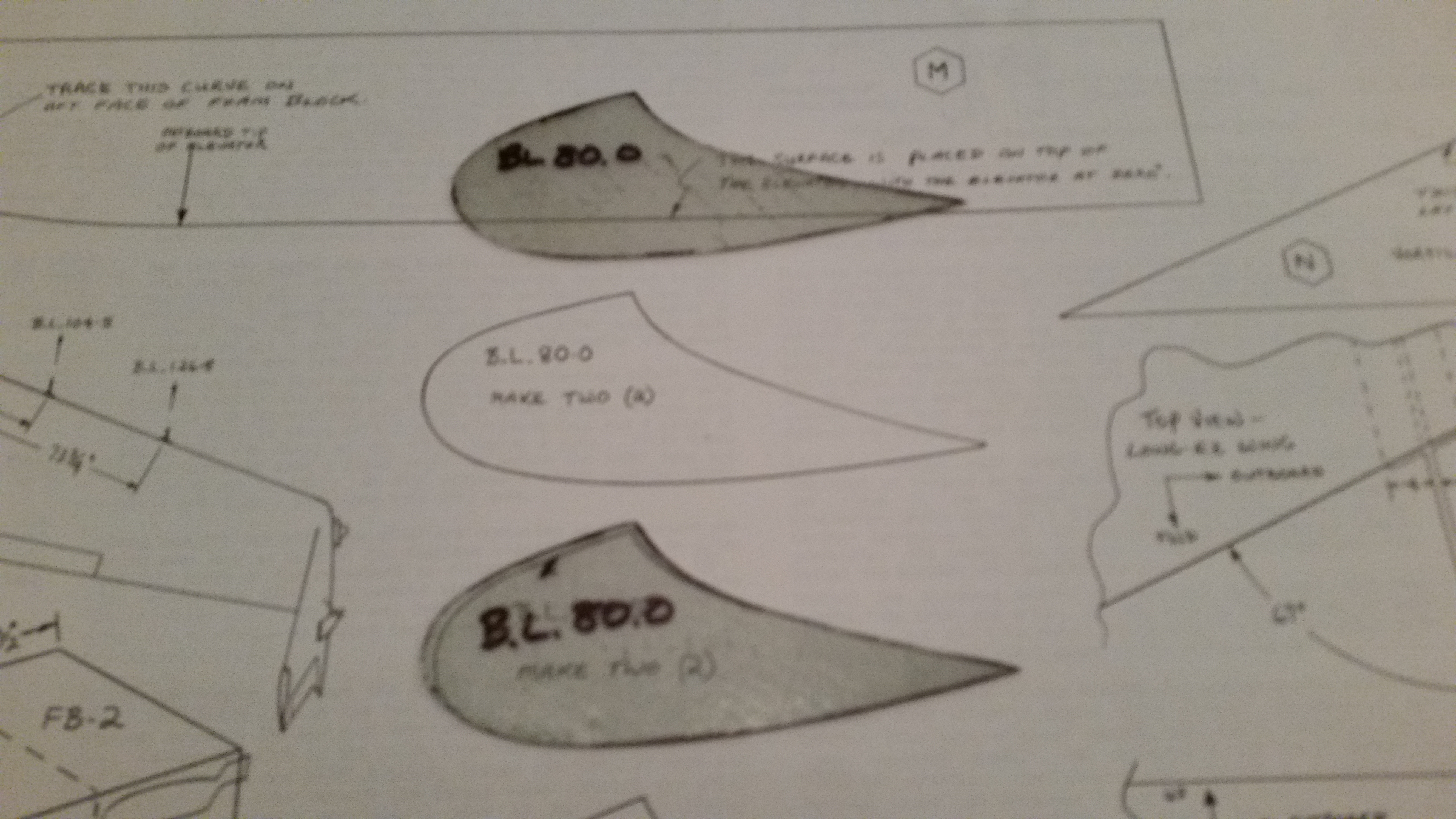
I used the Canard Bottom Contour Checking Template to see how the bottom of the canard was measuring up before I mount the canard to the K-jigs.
I also took a minute to remove a big unsightly run of dead micro that needed to go away.
I then weighed down the canard after using 5-minute glue to bond the canard to the K-jigs.
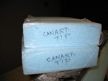
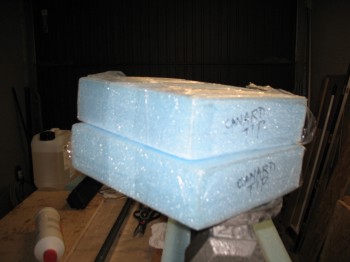
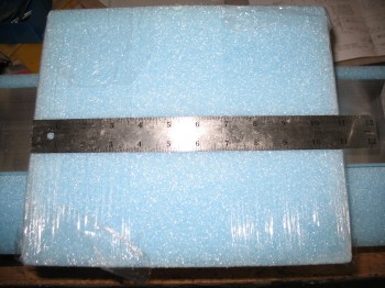
I then grabbed the 11″ canard extensions & removed them from their foam encasements.
It was then that I had a total brain-fart, disregarding all my jedi-training, and grabbed the bottle of “Hot Stuff” glue (Superglue) to mount the 11″ foam extensions. Right after I mounted the canard tips on the Outboard K-jigs, I realized in short order what I had done (luckily, most of Hot Stuff glue soaked into the particle board K-jigs, so the damage was minimal). After my duh moment was over, I whipped up some flox to keep the canard tips mounted since I had already micro’d & nailed them into place. I also double-checked that they were straight & level on the LE, TE, top & bottom.
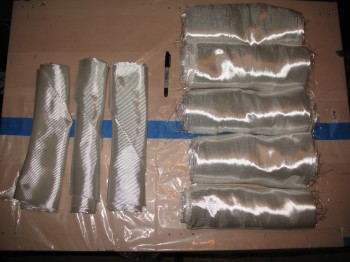
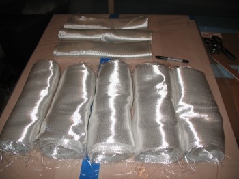
As the canard tips and structure cured to whatever degree it had left to the K-jigs, I went down to the cutting table and spent a couple of hours cutting the glass for the canard skins. I cut all the UNI for the top & bottom skins (5 pcs 12-1/2″ x 134″), and enough BID for the bottom skin (3 pcs 13-1/4″ @ 45°).
I pre-deployed the slow hardener, 3″ UNI tape, etc. to the garage.
•••
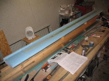
1 May 2013 — I checked the Roncz Canard 11″ tips that were micro’d on yesterday. Everything cured well so I pulled the nails that were holding the foam pieces together. When I leveled out the canard, I could see where the 11″ canard tips were slightly off from the rest of the canard. So I took my time and very carefully sanded the canard tip bottom surfaces to match the rest of the canard. I did this for both the Left & Right side.
I then precut the 7 each 3″ UNI tape lengths: 108″, 108″, 98″, 90″, 80″, 60″ and 12″. Since the Roncz Canard plans state to simply layup the number of lengths that will appropriately fill in the spar cap trough, I can make modifications to my UNI tape lengths if and when they may be required. I wanted to have as much of the prep work completed, since I will take Burt’s advice in the Roncz Canard plans and layup the 3″ UNI tape spar cap glass and then roll right into glassing the lower skin of the canard.
I carefully sanded the LE edge to knock off any excess foam from the hotknife cutting process, then vacuumed the entire canard and taped half-way up the LE.
I tacked on a 1″ strip of peel ply down the entire TE, but with only 1/2″ on the TE and the other 1/2″ hanging overboard. Once I finished with the peel ply, I taped around the spar cap & used plastic to protect the canard foam surface.
I bagged (like a wedding cake frosting bag) thick micro around the edge of the spar cap. I then laid up the spar cap using the contour template regularly to check the amount of glass in the trough.
I was using a whole new batch of 3″ UNI tape that I ordered just before I left Tampa, and I have to tell you I didn’t like the new stuff at all. There must be a new supplier to ACS because the roving threads continuously broke while trying to remove them from the glass weave, and I even found a piece of scotch tape holding the glass weave together (thankfully only once), which of course I cut out.
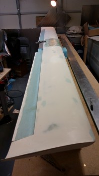
Once I was finished laying up the spar cap, I took a very short break, then carefully removed the protective tape and plastic from around the edge of the spar cap trough. I then used micro paste to fill in the joints & dings, and then microslurried the remaining canard bottom blue foam surfaces.
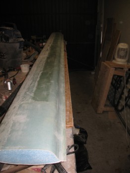
I then laid up the bottom canard skin which was fairly straight forward: 1 long layer of UNI, 1 long layer of BID (4 pcs total & only overlapping in the center, not on the Outboard flight surfaces), then 1 long layer of UNI again, for 3 total layers. The UNI is somewhat of a pain to work with at times, since it’s cut with the strands of glass, so the glass continuously wants to peel off the sides of your layup. Dale Martin recommended that I do like many builders & cut the UNI here just a tad wider and then masking tape the edges to keep it from unraveling. I was too lazy & cheap to do that, so I just powered through.
Once I glassed the lower skin layups, I knife trimmed the edges to 1/4″ and peel plied the LE with 2″ wide peel ply tape. I also peel plied around the canard mounting tabs.
After a few hours had passed, I used a razor knife to cut the glass along the middle of the LE adjacent to the line of duct tape underneath. While I was pulling away the duct tape, dead glass and peel ply, I had about a 10″ section of LE foam that simply decided it wanted out and peeled off with the tape. I will have to fix that area before glassing the top of the canard.
With that, I double checked the layup and then let it cure. One thing I did notice is that in a couple of areas the spar cap is a hair thicker than it should be. So there’s about a 0.05″ ridge along the spar cap edge under the skin. The bond looks good, there is just that small ridge that I will have to contend with when finishing the canard.
•••
2 May 2013 — I checked the canard to ensure everything was good with the layup from yesterday. All was good except for the LE foam damage.
I pulled the 2″ peel ply off the front LE & around the mounting tabs and took a few minutes to clean up the peel ply boogers.
I then “Fein” sawed/razor cut each of the canard ends so the glass was flush with the foam. I also clamped a straightedge onto the trailing edge (TE) and cut it as well.
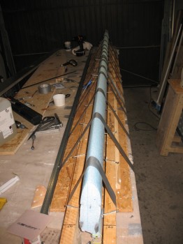
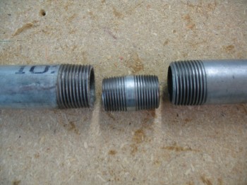
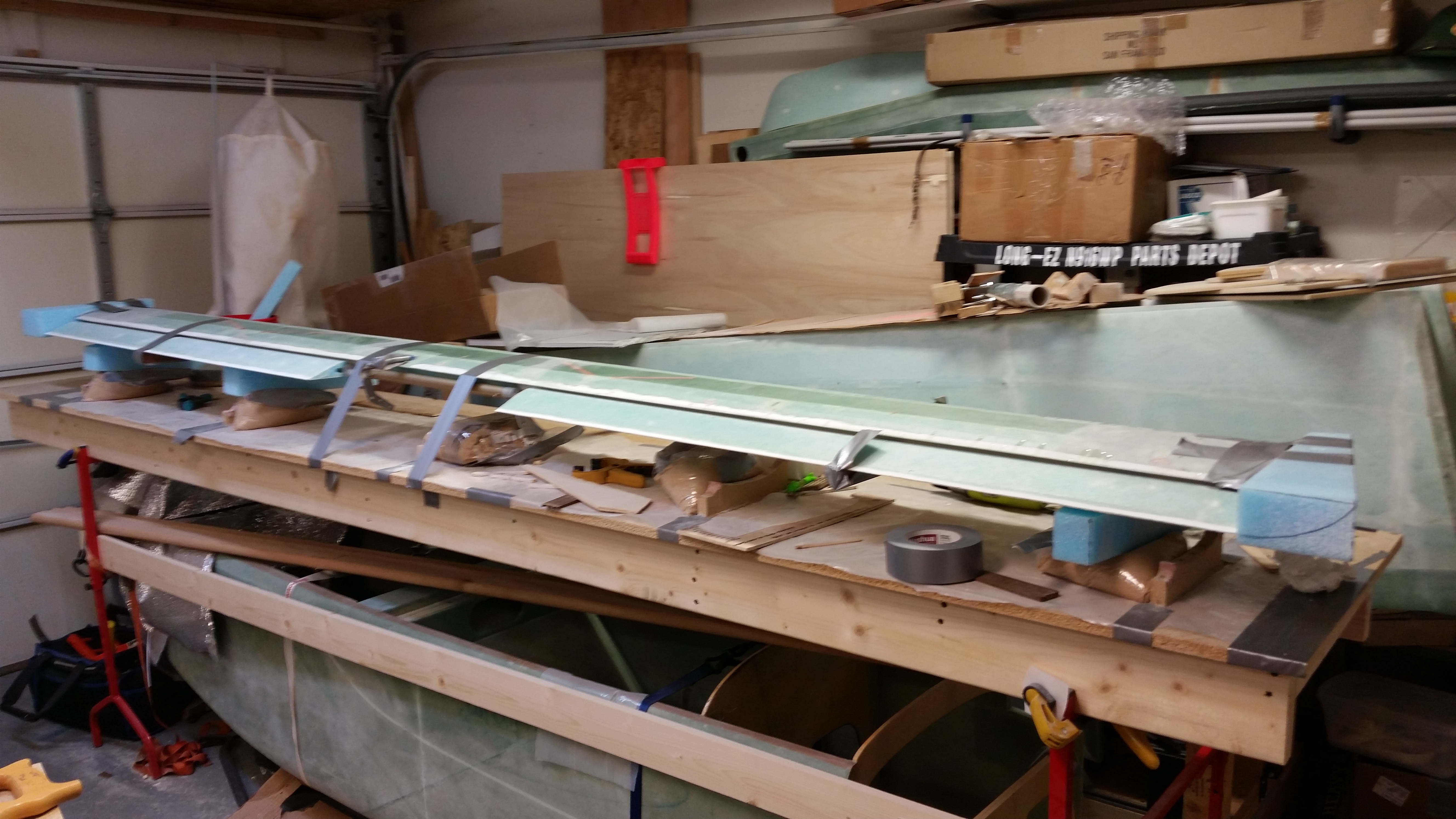
I had looked high & low for weeks to find a 130″ long pipe that would work as the TE alignment pipe. I even borrowed a pipe from the Civil Engineers on base, but it wasn’t straight when I checked it out at the house. So I went to Praktiker & bought a 2000 mm (~78-3/4″) and 1500 mm (~59″) 1″ water pipe. I used a 3/4″ threaded connector to help keep the 2 pipe pieces together & straight. I cleaned the pipes with acetone & then Simple Green and then mounted them together.
I then bondo’d the whole assembly to the TE lip of the canard, using my aluminum straight “board” to make sure it was all straight.
I trial fit, and then cut crescents in the wood support boards, that would hold up the canard when it was flipped over right side up.
After I got the 4 support boards prepped, I bondo’d them to the bottom canard surface on one side and the metal pipe on the other.
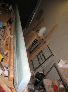
I then flipped the canard right side up & secured the end wood supports to the original wood canard jig base.
I cut off the fishtail at the topside TE. Once I got the fishtail foam removed, I then removed all the tacks and peel ply from the TE.
I used the top contour checking template to finish sanding the remaining foam off the TE area left by removing the fishtail.
Before the final mounting of the canard to the original base, I took it out of the garage and flipped it around end-to-end so that I could work on the LE with it at the front edge of the table, facing both the lighting and closest to the epoxy table. Then I spent about 2-1/2 hours using straight edges, string, and a laser level kit to get the canard as perfectly aligned as possible. I had about a 0.15 inch drop at each end, so I shimmied the each end support strut with a couple of stirring sticks, which seemed to do the trick.
•••
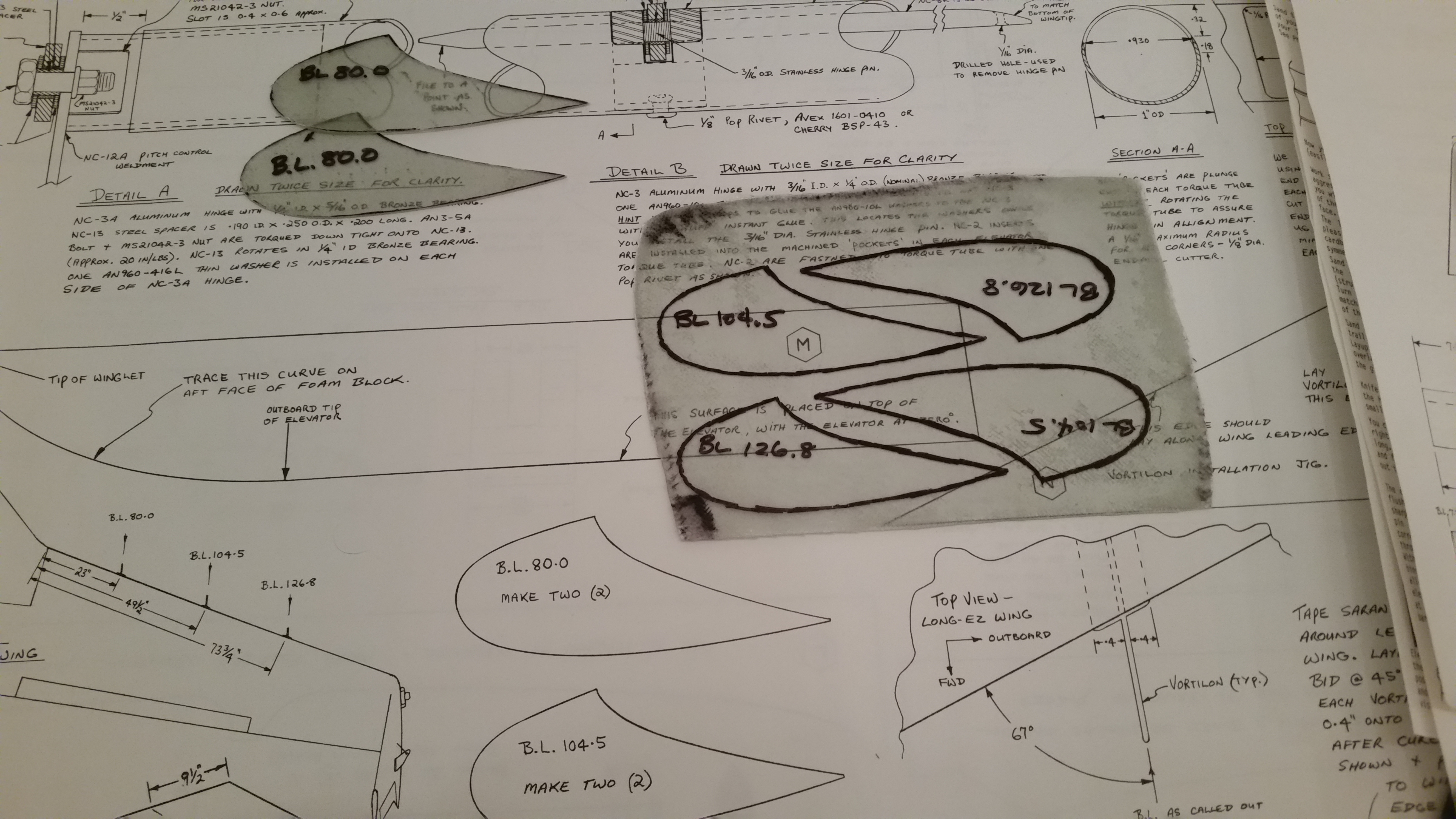
4 May 2013 — I spent an hour or so researching and planning the torque offsets configuration & hinge placement.
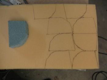
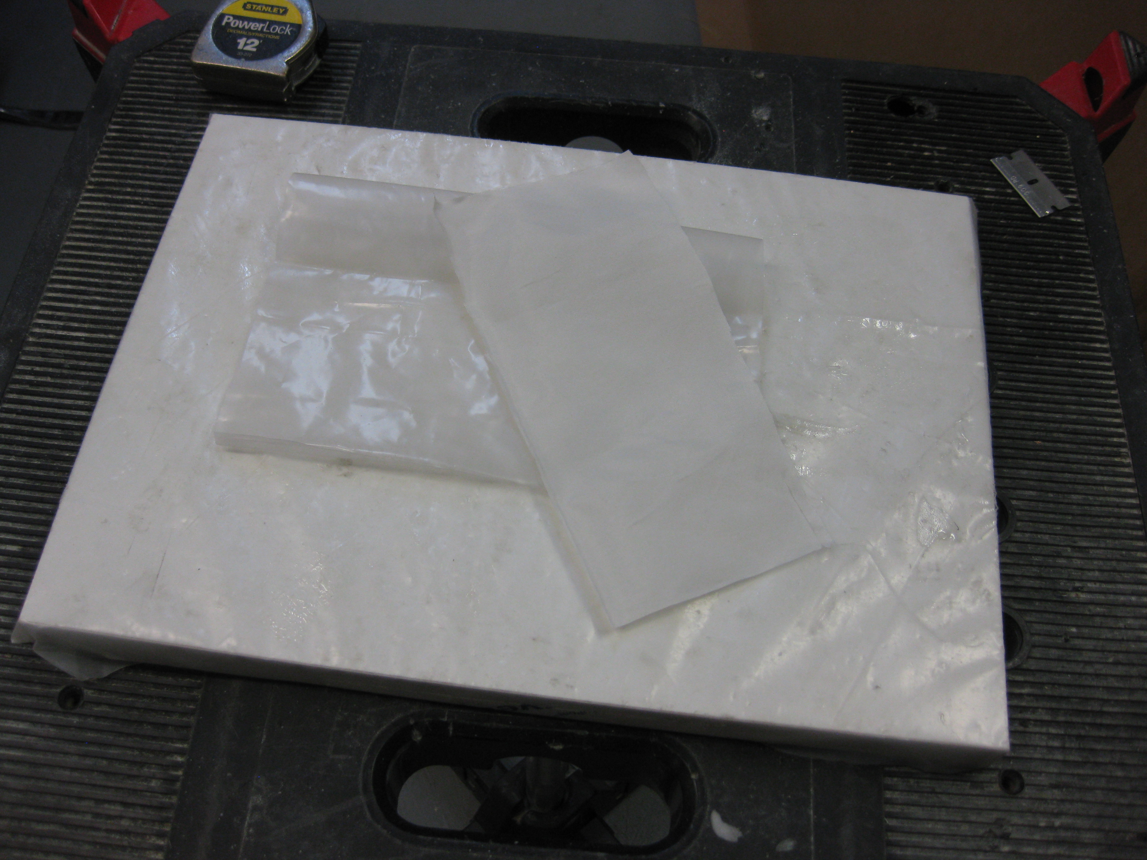
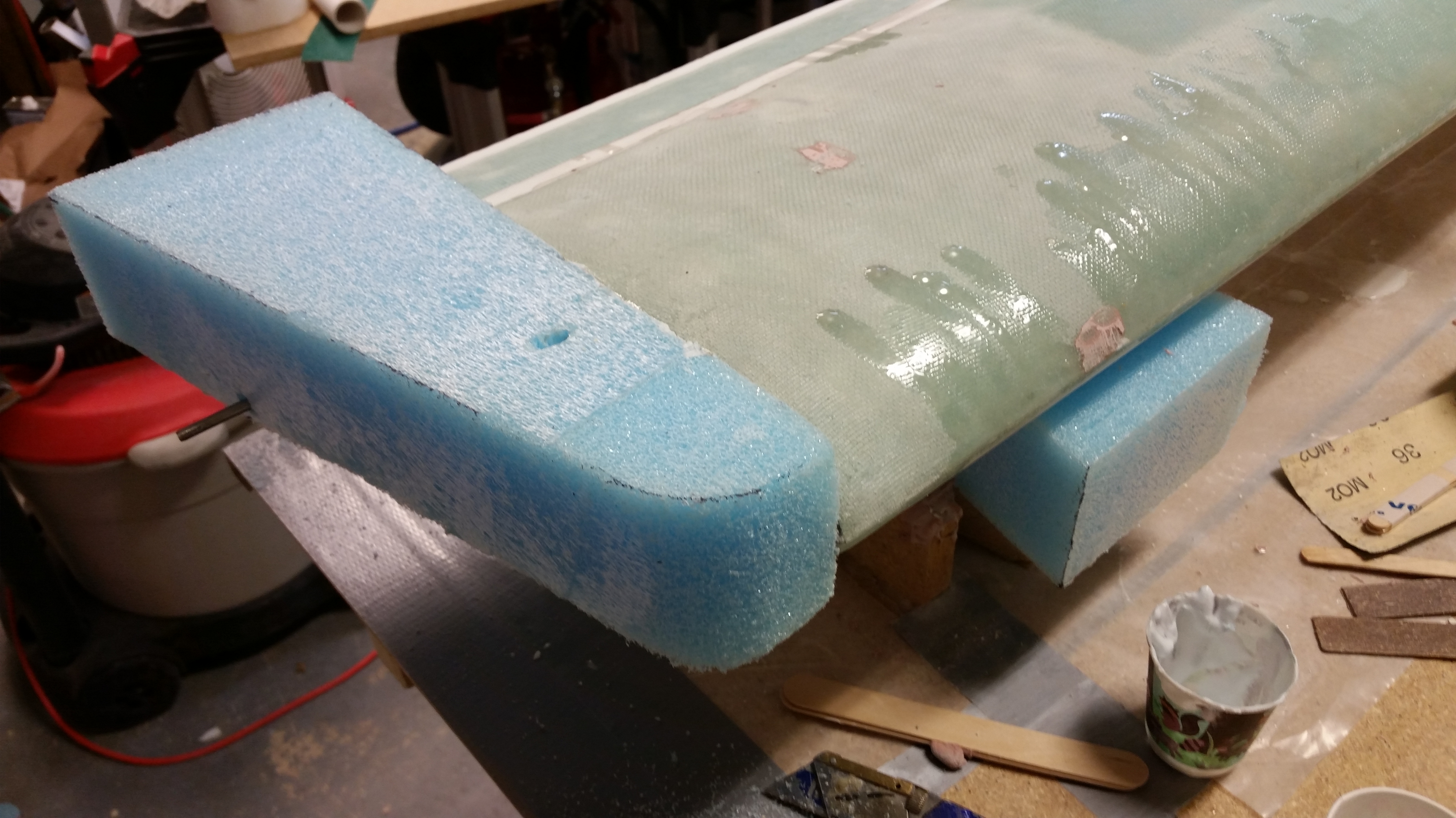
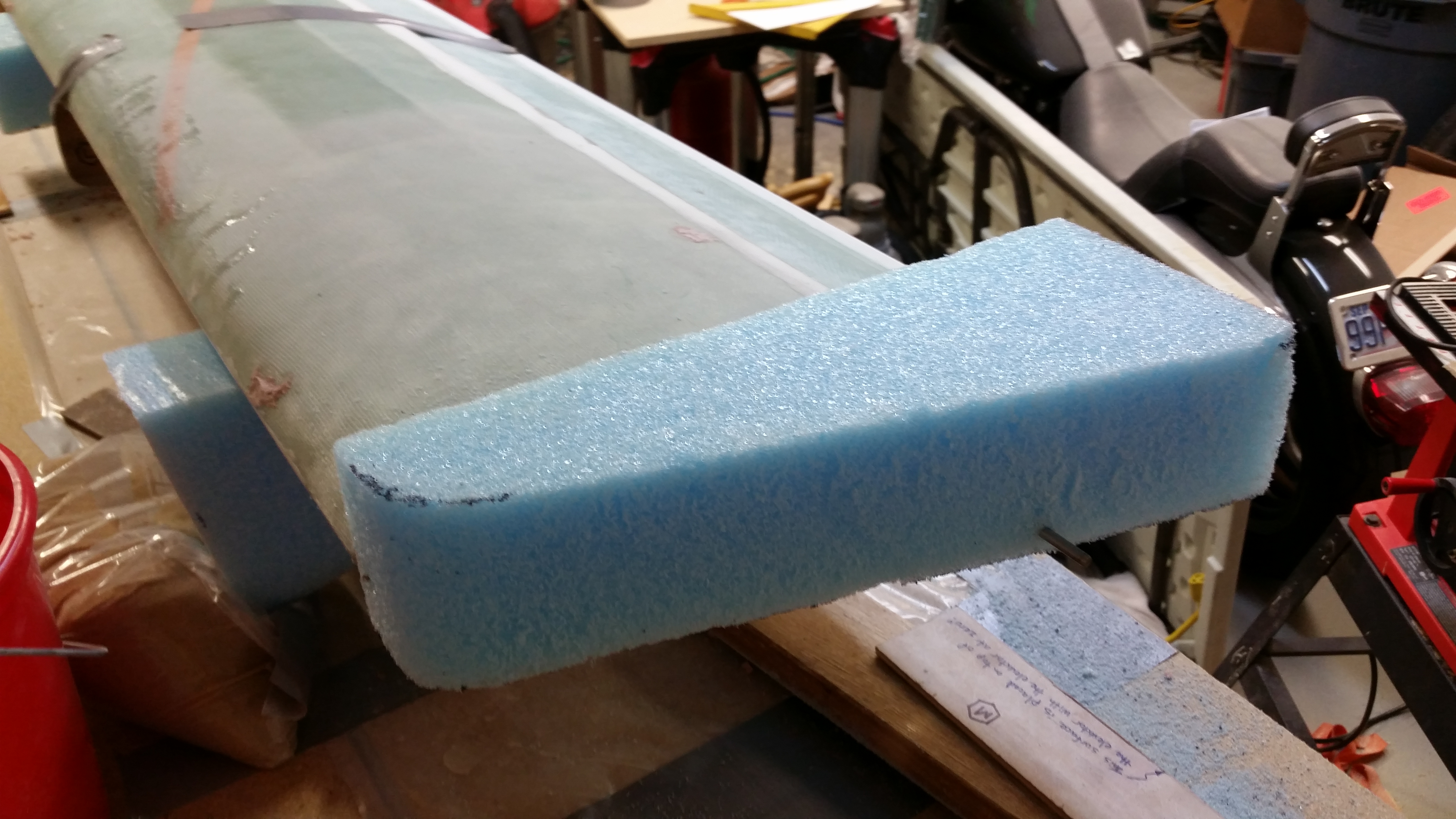
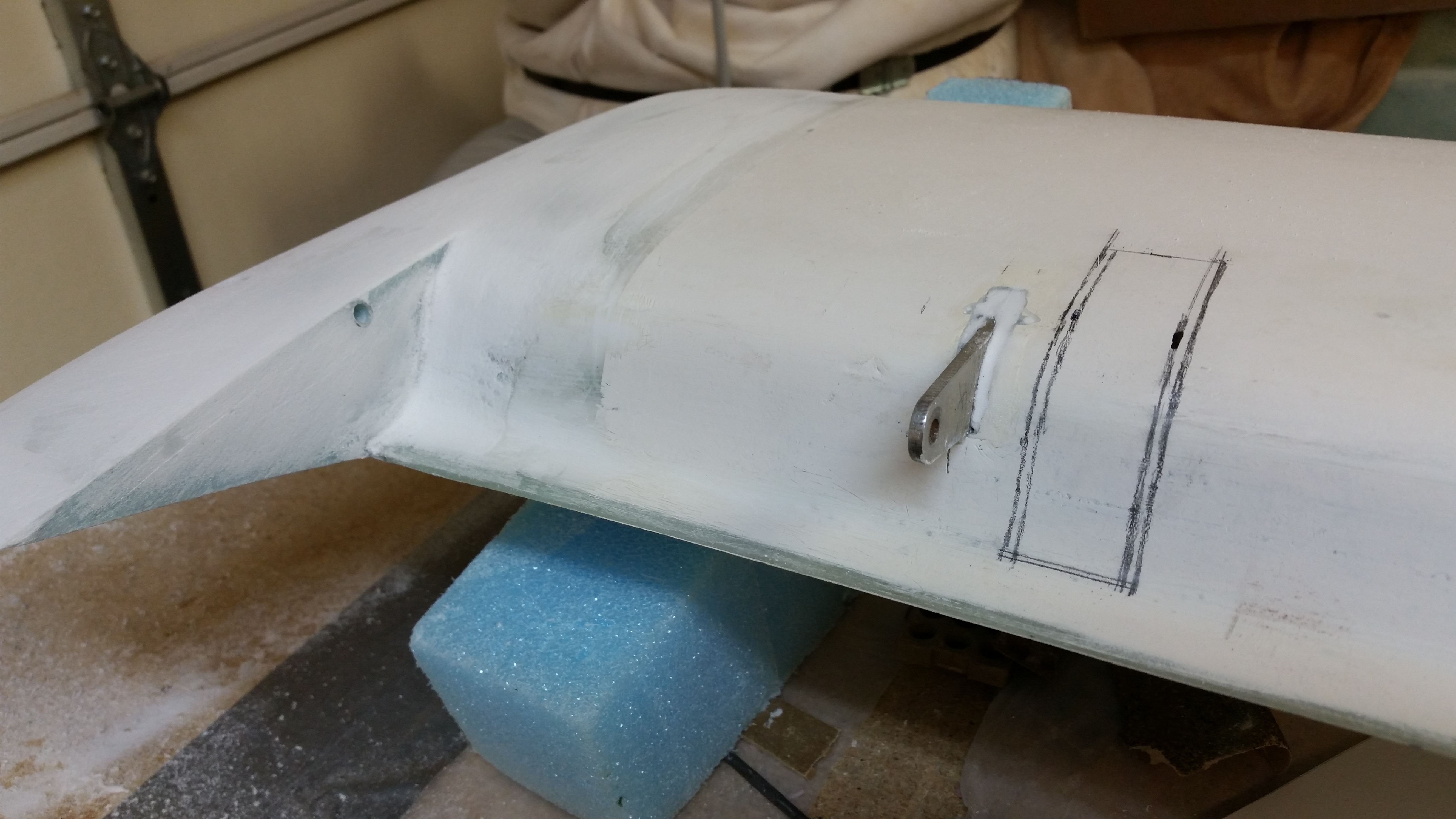
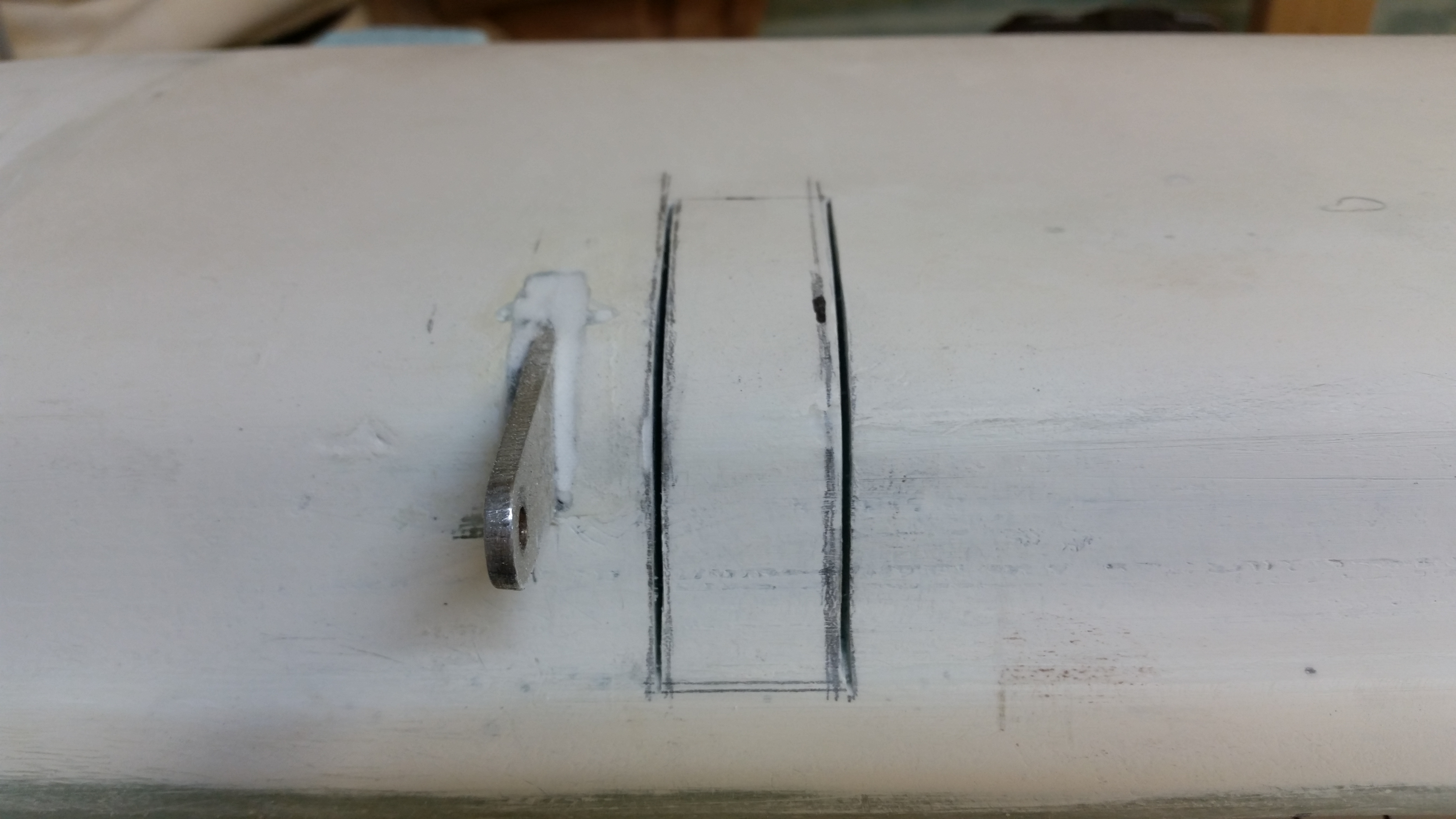
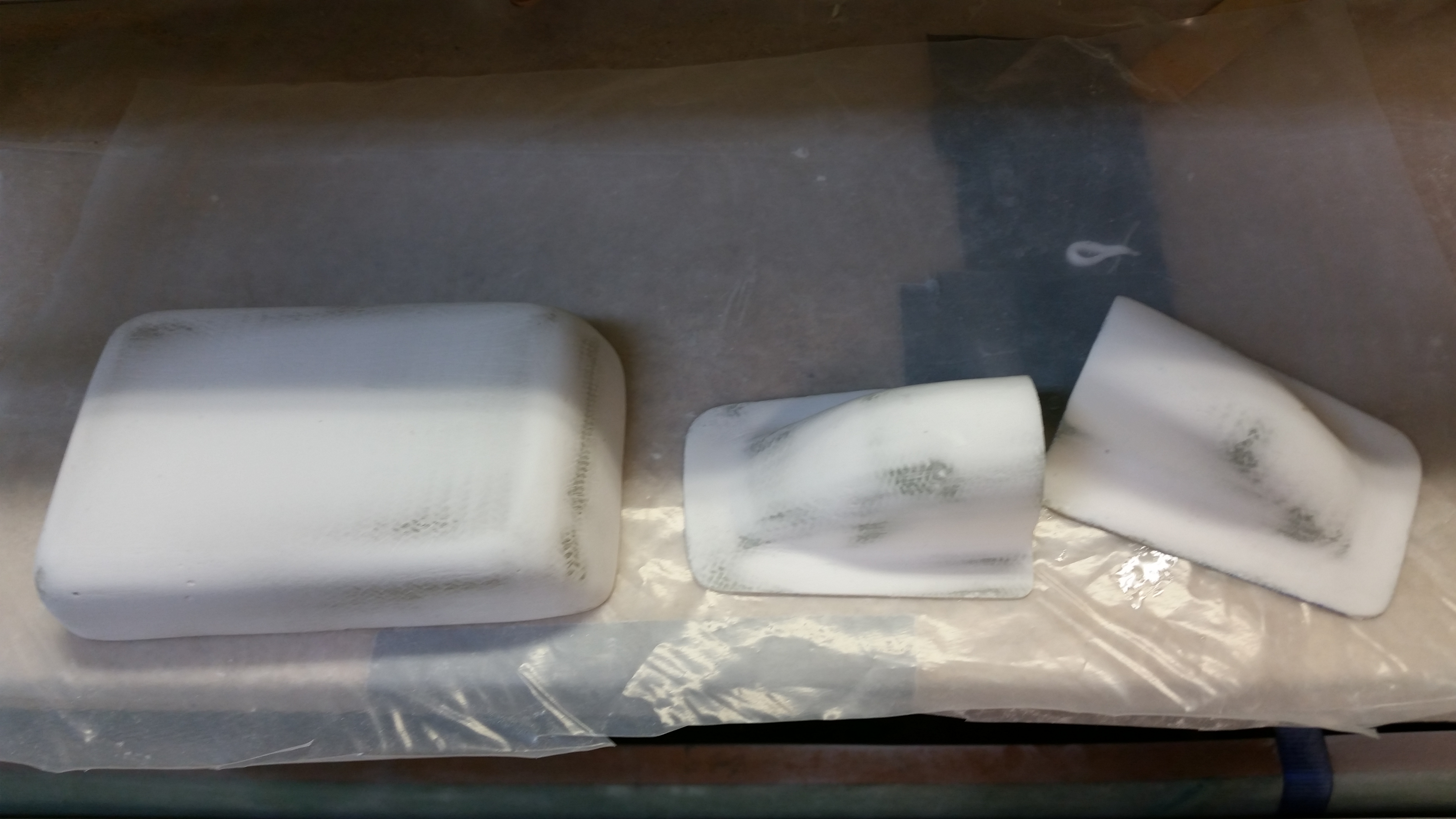
I rounded up my block of 6# high density foam.
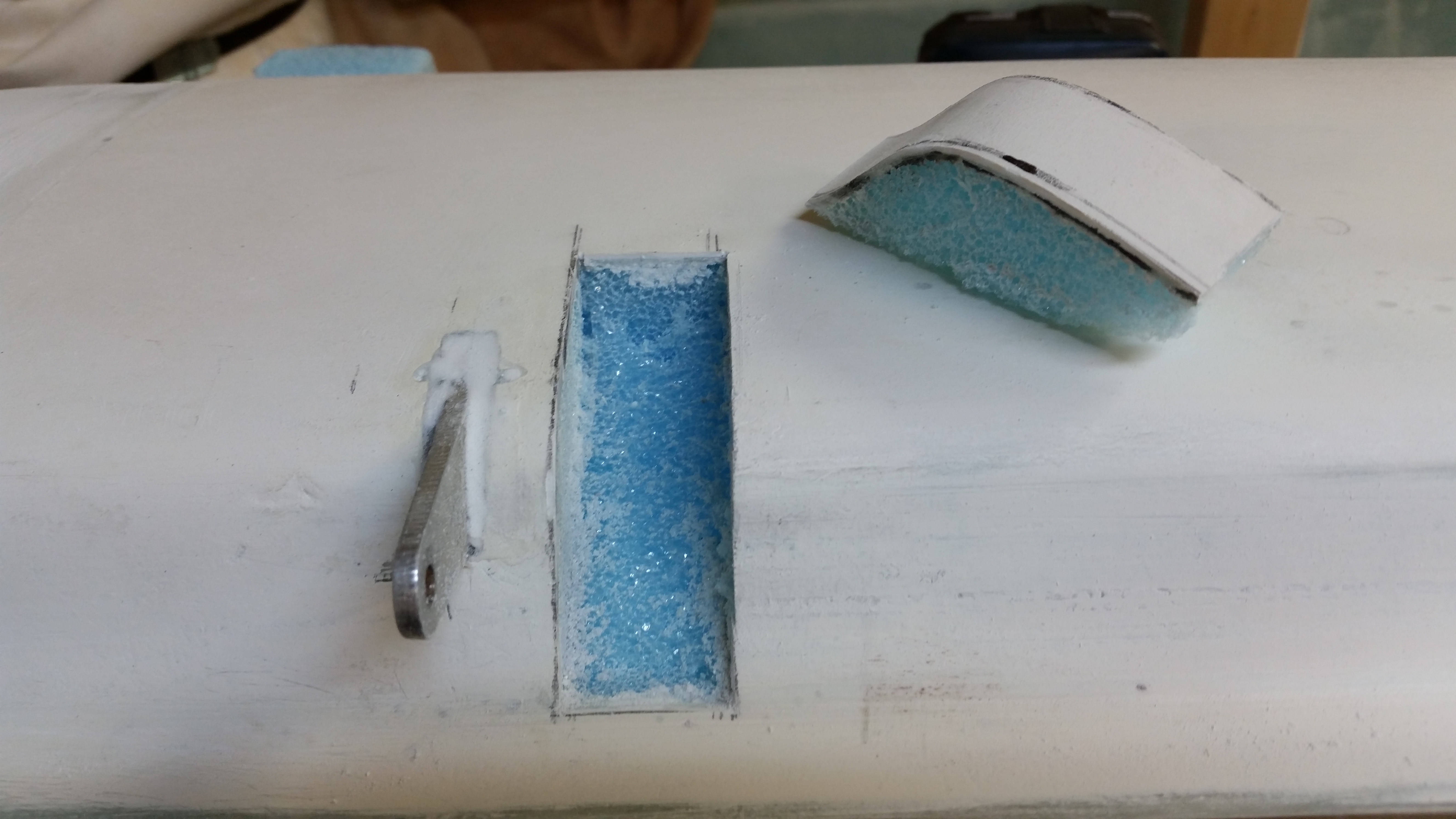
I “designed” my insert with a scrap of blue foam and once I had it locked in & test fitted into the canard, I used it as a template for the high density foam inserts.
I test fitted 2 of the inserts and they fit well, but I didn’t micro them in place yet. This foam is tough stuff!
•••
5 May 2013 — I finished cutting all the H100 6# high density foam inserts and their respective positions in the canard (L&R of CL: 9.7″, 34.1″ & 59″).

I micro’d in the high density foam pieces into place.
•••
6 May 2013 — I cut 4 pieces of BID 13.5″ wide at 45° for the Canard top skin.
•••
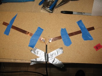
9 May 2013 — Today I made the 2 canard antennas that will be mounted under the top skin. I’m using the antenna kit from RST Engineering and following the guidance & instructions of Jim Weir.
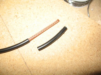
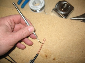
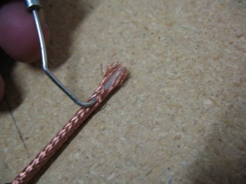
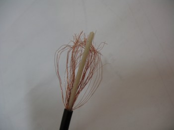
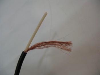
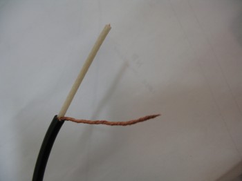
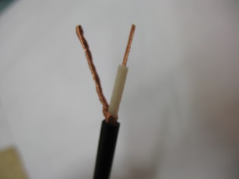
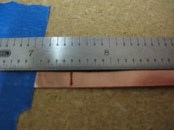
I made the VOR antenna first, with each leg (or “ear”) of the dipole measuring 22.8 inches in length. I’m also using 50 Ohm RG-58 stranded antenna cable.
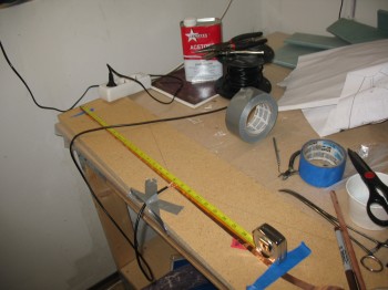
The following pictures show the general steps I take to make an antenna using Jim Weir’s design. I will say that going back and reviewing the instructions on how to make these antennas, I should have probably cut the leads a little shorter that attach to the copper foil. Of course I think the antennas will still work fine, they’re probably just not as optimized as they should be for Tx & Rx, although most of these only receive anyhow.
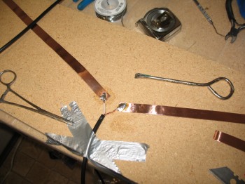
I made the ILS antenna next, with dipole legs measuring 7.5 inches.
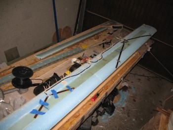
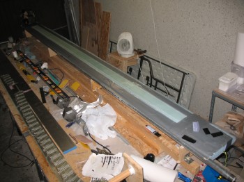
I then mocked it up on the canard as well to figure out the best placement for both the VOR & ILS antennas.
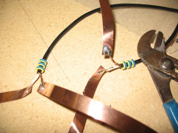
The picture below shows the 3 Ferrite Toroids that are placed on the RG-58 Antenna cable close to the dipoles on about a 1/4″ spacing. The ferrite toroids strip off any reflected power from the antenna (technically the outside of the coax braid) before it can get into the electrical system. Using 3 ferrites eliminates about 99.9% of the reflected signal.
These 2 antennas make up the last of the copper foil antennas that will get embedded into the skin of the flying surfaces. Here is a summary of all my copper foil antennas:
COM1 – Left Upper Winglet
COM2 – Right Upper Winglet
VOR1 – Left Wing
VOR2 – Canard
ILS – Canard
FM Radio – Right Wing
•••
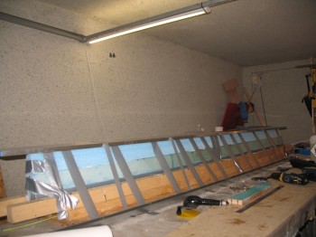
10 May 2013 — Today I spent a lot of time ensuring the canard was straight and level. I used strings, I used the aluminum straight ‘board’, I used the contour checker, I used the 6 ft carpenter’s level and I used a laser level kit. I checked, leveled, shimmed, re-checked, re-leveled and re-shimmed countless times. Obviously this is my final time for ensuring the canard is straight, twist-free & level before the spar cap and especially the top skin is glassed (this warning is explicitly spelled out in the plans as well).
There was a very slight twist to the canard which I remedied through shimming. One thing that kept perplexing me, until I finally cracked the code was that the top middle of the canard dipped down a bit, but then the bottom of the canard was slightly crowned. I realized after finally working the problem with both sides together, that my canard was slightly hourglass shaped. Well, at least it was symmetrical! I took a long look at it, and concluded that a good amount of the narrowest part of the hourglass shape will be stuffed away in the middle of the fuselage. Apparently this was the shape as it came out of the hotwire cutting process. There would be some narrowing (thickness, not width) towards the Inboard canard area to contend with, but it wasn’t extreme enough to start over or panic. It looked like there will just be less micro filler towards the Outboard canard ends and just a tad thicker micro fill towards the Inboard areas.
I moved on to getting the spar cap layup knocked out. I sanded the shear web/spar cap trough. I did also sanded down and shaved a little off the Outboard 11″ canard tips to match the rest of the canard shape. I taped the edge & added plastic around the entire perimeter of the spar cap trough.
I micro’d the edges of the spar cap trough. I cut & laid up the 3″ UNI tape, and ended up using 9 pieces in the following order: 108″, 92″, 103″, 70″, 81″, 50″, 60″, 30″, 18″. I then peel plied the entire spar cap layup.
About an hour after I finished, I removed the protective tape & plastic from around the newly glassed spar cap.
•••
11 May 2013 — I started off today by hot gluing the outside corners of the canard jig that I had been messing around with yesterday while leveling the canard & ensuring it was straight.
I then cleaned up the spar: sanded, Dremeled, & prepped the LE & TE.
I then cut the antenna cable runs & installed the canard VOR & ILS antennas.
I vacuumed the entire top surface of the canard & made a final check of my preparations before starting the final main skin layup.
I used a mixture of fast hardener for the dry micro paste for all the heavy dings & divots, and around the installation of the antennas. I used a ~50/50 mixture of micro & flox for the LE prep. Something I may not have mentioned before, but something I’ve noted to building buddies of mine is that my unofficial ratio is that for about every hour worth of glassing I do, it seems like I have about 8 hours of actual prep (NOT researching & studying the plans, etc.). On this layup it took about an 1-1/2 hours just to finish prepping all the foam with micro.
I used fresh epoxy to wet out the LE, spar cap, TE glass. [Note: I think it’s worth reiterating that glass surfaces always get a coating of epoxy (normally) or flox (occasionally), which are structural, but never micro–which is not structural–in between the layers of glass].
I glassed 1 long single ply of UNI, a 4-piece layer of BID, and then 2 more long single plies of UNI… with 2 small holes in the middle for the antenna leads ~ 5.5″ & 4.0″ Left of CL.
I used toothpicks to the hold antenna leads straight while glassing the individual skin plies, and then used a makeshift taped Popsicle stick contraption to hold it at the right angle after all the top skin was glassed and the antenna lead area was peel plied.
I also specifically peel plied the Left Outboard LE area that was damaged by the foam being removed. It’s a slight flat spot that’s about 5 inches long, which I will just add a 2-3 ply glass patch and then shape it afterwards after this main glassing is completed.
I checked the layup about an 1-1/2 hours after I finished and found a bubble a little over 1 inch long & about 1/2″ wide right over the edge of the spar cap, on the Left side about 6″ Inboard from the seam with the 11″ tip extension. It looked like it might be internal air off-gassing through the seam of both the spar cap and maybe even up through the top of the internal shear web. I “popped” the bubble with my scribe, added just a dab of wet epoxy and re-squeegeed out the bubble.
Another area that I wasn’t overly happy with was the contour of the TE, after using the contour checking template. Although I had built to plans, there was a trough/depression running down the entire length of the TE, not unlike the TEs of the main wings or winglets. So, while not called for in the plans, I filled in the TE trough with dry micro while the glass was still tacky and not yet cured.
•••
12 May 2013 — I snapped a couple of pictures of the canard with the elevators.
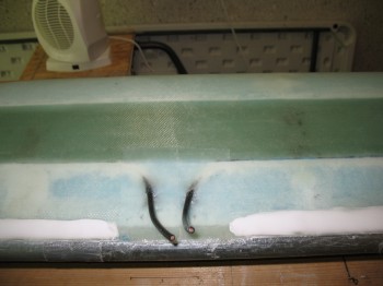
Below are a couple shots of the canard antenna leads:
•••
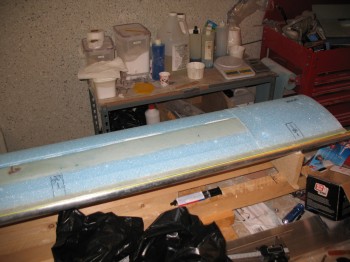
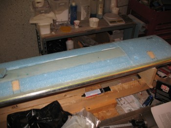
15 May 2013 — I had left the canard alone after its final topside skin layup to cure a few days to ensure its configuration was locked into place. I figured it had cured to a good degree, so I popped it off its glassing jig. This of course involved removing the heavy water pipe attached securely to the TE.
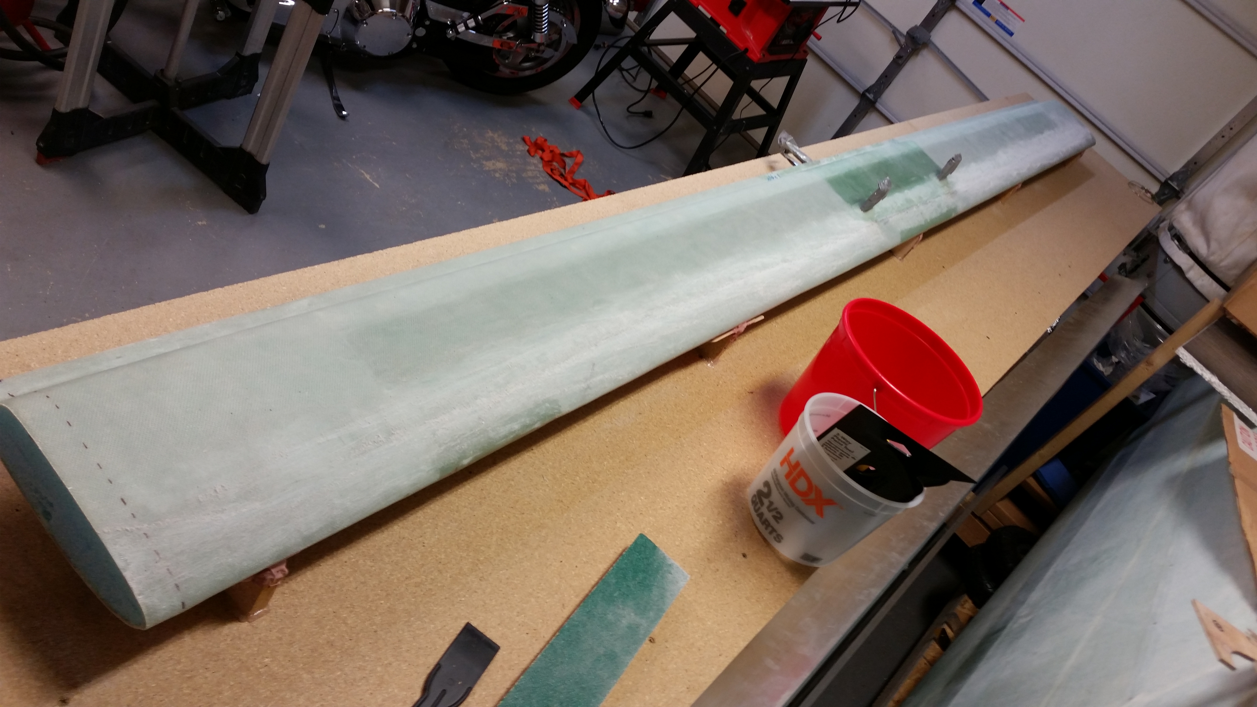
I then flipped it over to see how the underside looked. Not bad. I was very happy with the overlay of the top skin over the bottom.
•••
17 May 2013 — I spent over 2-1/2 hours today sanding the canard. I started by sanding the 2″ LE overlap on the canard bottom, and some spar cap area too.
I sanded off the bondo in 4 places along the bottom of the canard where the canard had been attached to the wood support struts. I then also sanded the bondo off the TE overhang.
I took a string & strung it out between the corners of the trailing edge and sanded the TE straight.
•••
21 May 2013 — I took a shot of the canard & the elevators below. I should probably mention that I’ve halted my canard building efforts for a few reasons: A) As with all my other components, I have to ship the canard back and want it as short as possible. I really don’t want to mount the elevators without finalizing the outboard end-caps as a complete process. B) I have to get all the elevator control system pieces mounted together as an entire unit to know exactly where to mount the elevators, and I need a few pieces machined to do that, which is not happening here or soon. C) Randi & Chrissi mentioned that it is a lot easier to finish the canard first, then mount the elevators–thus making the finishing process go much faster & smoother. I’m taking this into consideration as well.
•••
15 June 2013 — I needed to get the canard out of the way in the garage. Before I put the canard in storage, I thoroughly checked it for any issues. The bubble I originally found just following the top skin layup right near the spar cap–which I had “popped” & re-squeegeed–had a couple of small air pockets. I drilled a few small holes and injected them with a very wet flox solution. Once I had these small bubbles filled, I let the wet flox solution cure for about an hour (I used fast hardener again) before taking the canard down the basement where it awaited getting crated up for shipment back to the States.
•••
14 April 2015 — It’s quite the rainy day in the Nation’s Capitol today. I took some time this morning to do some research on my sandblaster woes. I found out some great info, and as often is the case with Harbor Freight equipment there is a hidden set of gotchas that comes with it . . . awesome, cheap prices, but many times at the expense of having to incorporate some type of workaround.
Thus it is with my sandblaster. Even though I have an air dryer for my compressor, it is old and probably performing far below what it should be. At some point I’ll get a new desiccant filter for my air dryer, but to get moving quickly on this project, I simply bought an inline desiccant air dryer, along with an inline filter, while I was out buying a myriad of things for the next phase of this build. I’ll need to track down a few more things like higher end ball valves if I want this sandblaster to perform for a good period of time. I did hold off on buying any more blasting media until I conform my upgrades work. One last thing on the sandblaster: I learned that there is a definite trick in the order to which the 4 ball valves get opened, and exactly how far to open each of them to keep the media flowing, and not jamming up in the hose.
In addition, I bought some 12 ft long 2×6’s to use for the canard work bench that I’ll be building within the next few days.
Finally, as you may get a slight glimpse from the picture above, I spent over 2 hours last night doing nothing but cleaning & organizing the shop and putting all my tools back where they belong. With that, the start of the finishing of Chapters 10 & 11 looms ever closer!
•••
15 April 2015 — Since it wasn’t raining today, I started out today by picking up some particle board. I decided to use only regular wood, so I also bought another 12 ft long 2×6.
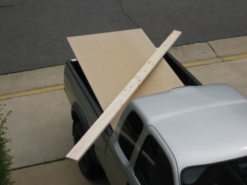
I checked both 2×6’s with my aluminum long board straight edge to confirm that they were straight. I have to say, they were both spot on. I was actually prepared to break out the table saw to trim the edges to ensure they were even, but luckily didn’t have to.
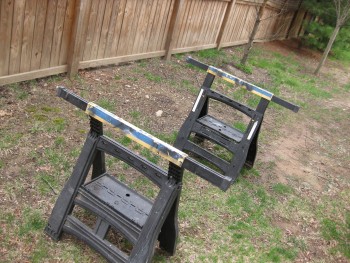
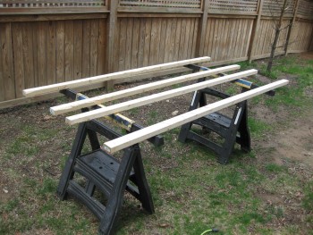
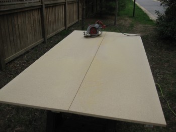
I set up my adjustable saw horses in the side yard in preparation for cutting the particle board.
I then placed 2×3 stringers on top to allow clearance for the saw blade & to support the cut halves of cut particle board sheet.
I hauled the sheet of particle board from the truck to the sawhorses.
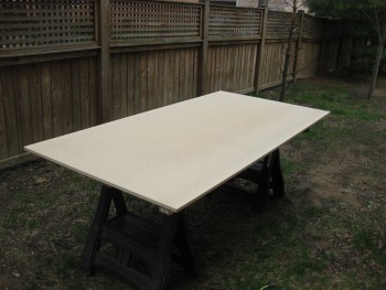
And measured & marked the cut line with a chalk line.
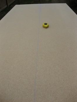
I then grabbed the caged “Beast” . . .
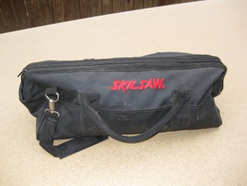
And unleashed it!
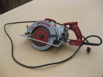
And cut the particle board sheet right down the middle.
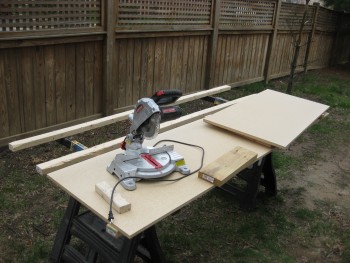
I then started cutting the cross support struts for the work bench.
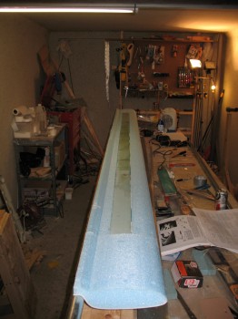
I pulled the canard down from its storage location on high.
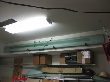
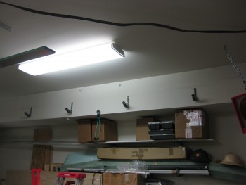
One idea I had to get the fuselage tucked out of the way while I work on the canard is to simply build a tall-enough work bench to stow the fuselage underneath.
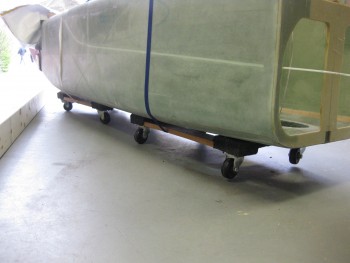
I put the fuselage on furniture dollies & strapped them with tie-downs to keep the fuselage in place. This simple task made moving the fuselage amazingly EZ & was really helpful in getting the shop squared away.
I then started building the canard work bench . . .
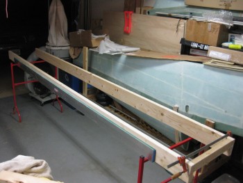
I screwed the cross support pieces into place.
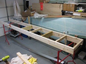
And then screwed the top pieces onto the work bench frame. You can see below that the fuselage fits fine underneath the canard work bench.
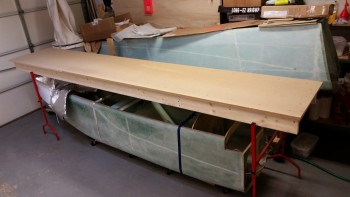
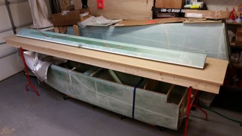
I then set the canard on the bench to see how much room I have to work with. It’s still amazing to me how long the canard is. Even with a 12 ft long table, there’s just enough room to work on the canard.
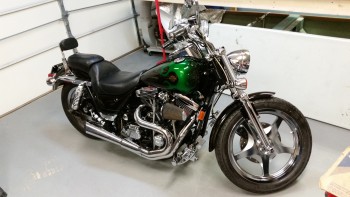
I did take a break before actually building the canard table to clean up the bike & take it out for a short scoot. Yep, this warm weather is awesome!
 •••
•••
24 April 2015 — I put this post under both chapters 10 & 25 because prepping the surface of the canard is a prerequisite for not only finishing the canard, but to glassing the canard “swoosh” tips to the canard & in optimizing the elevator install process.
How? Well, in yet another discussion with Randi from the infamous Cozy Girrrls, she highly recommended finishing the bottom side of the canard BEFORE mounting the elevators to exponentially decrease the time & effort it takes to finish the bottom of the canard with all the elevator mounting tabs in place. In addition, it helps knowing what the bottom contour of the canard will actually be when determining the spacing between the elevators & the aft edge of the canard.
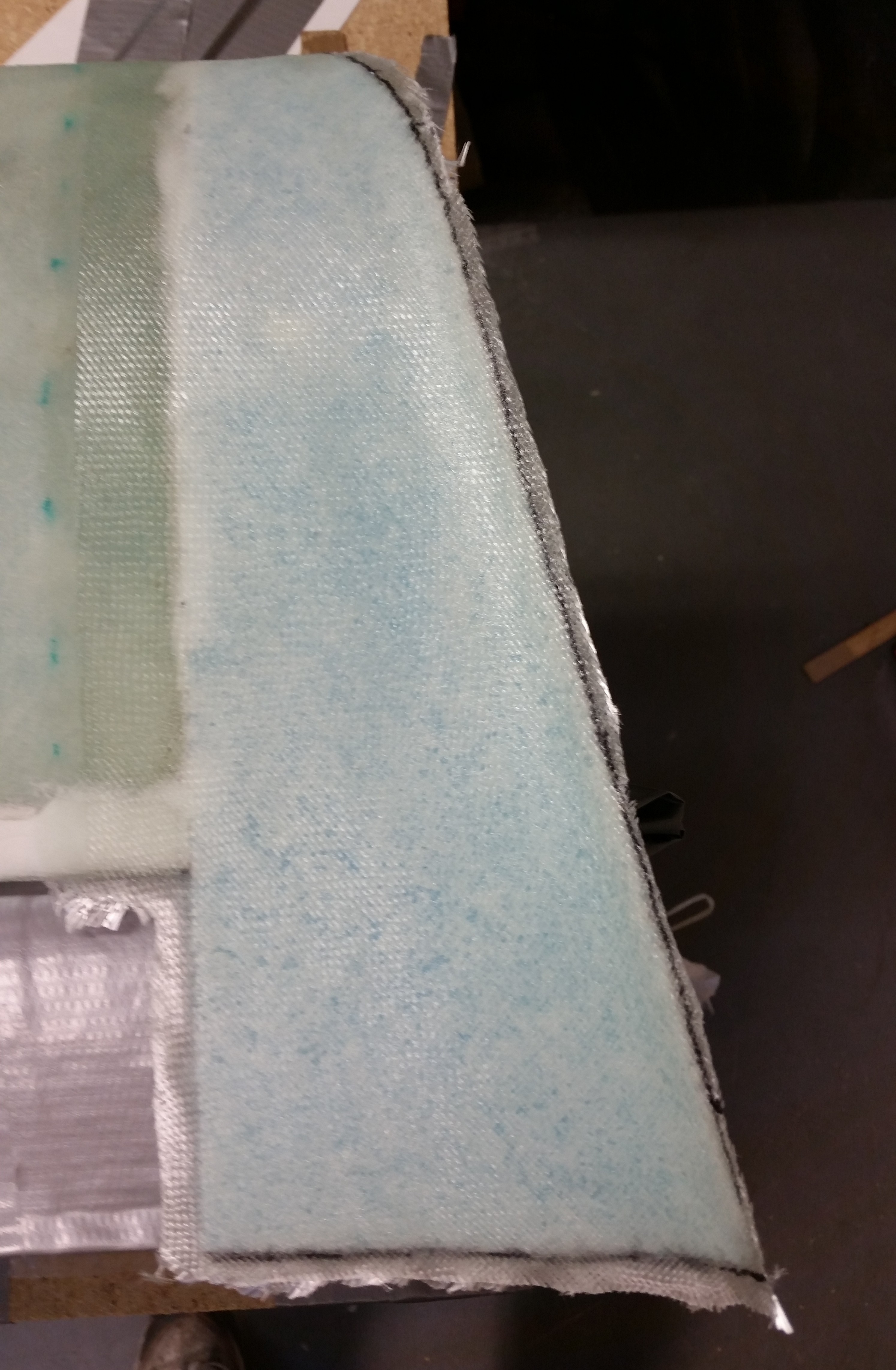
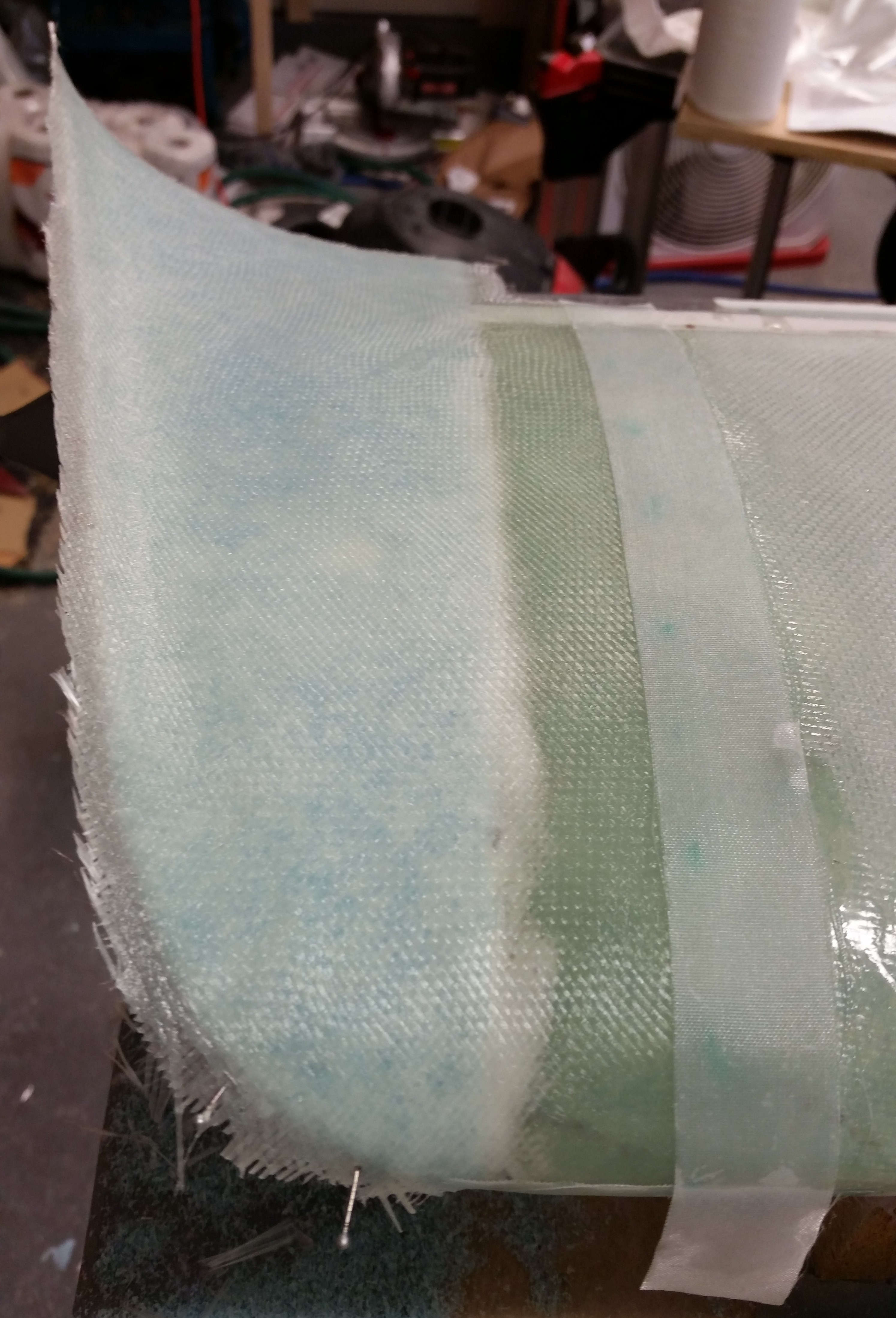
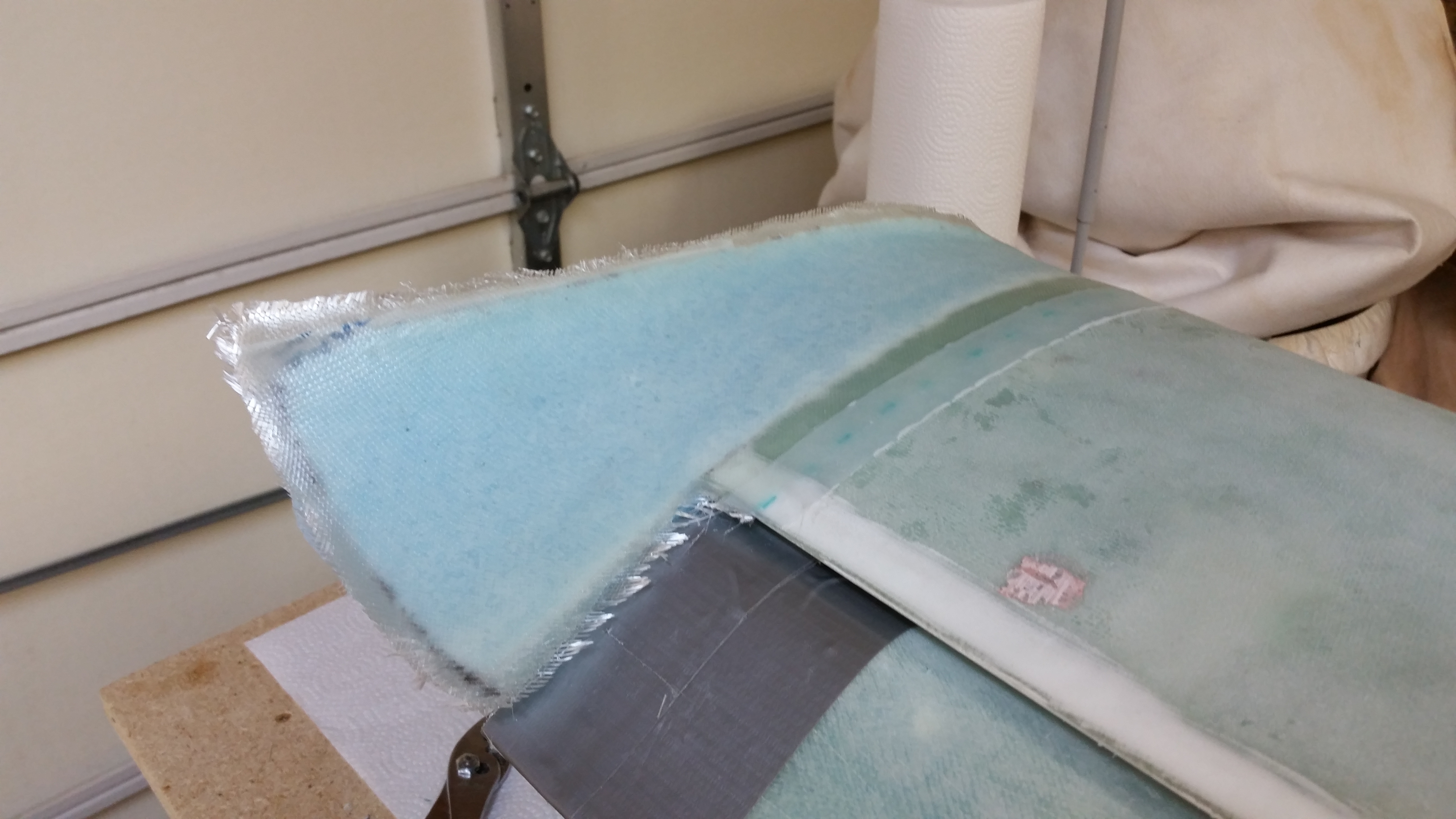
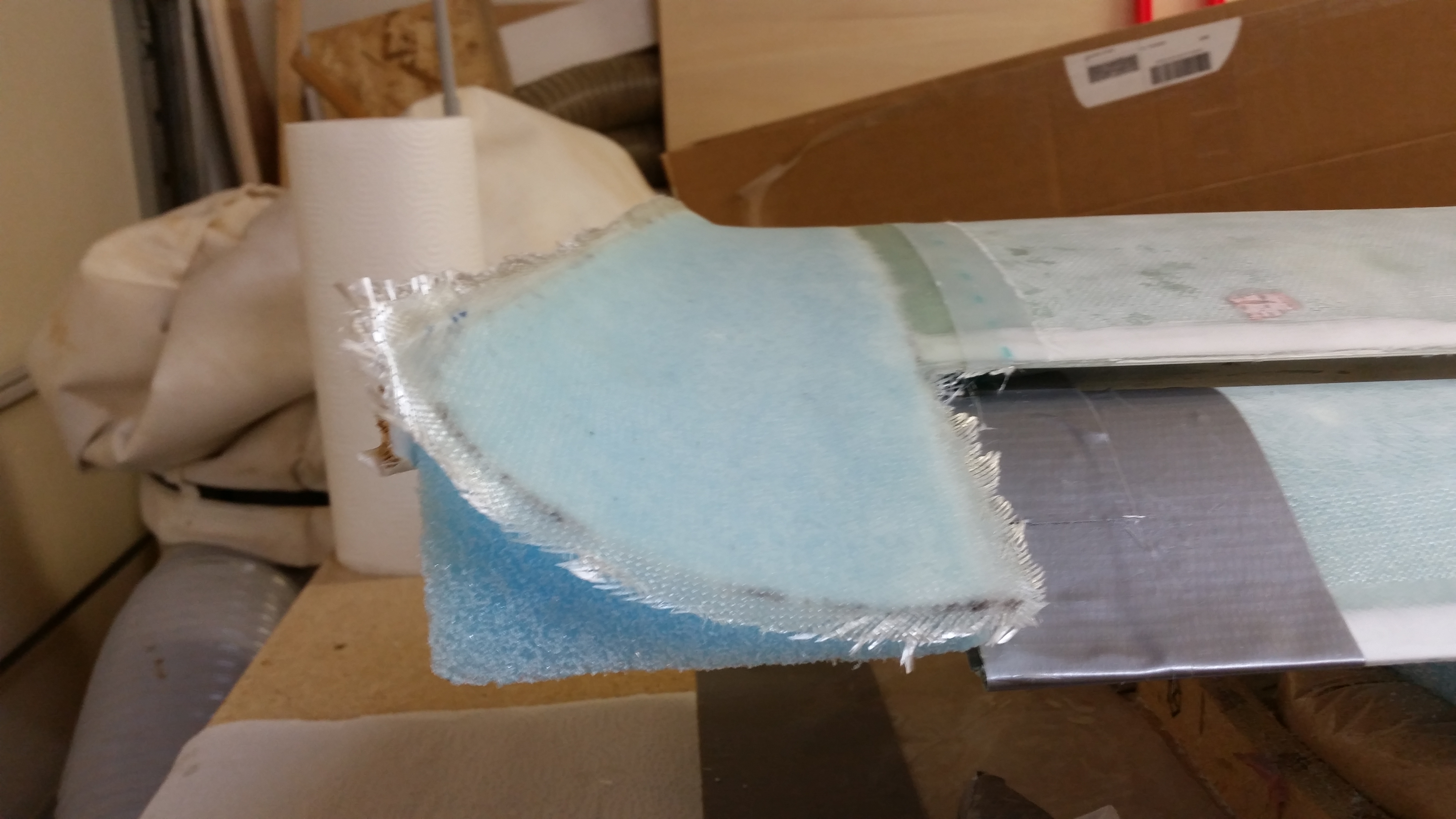
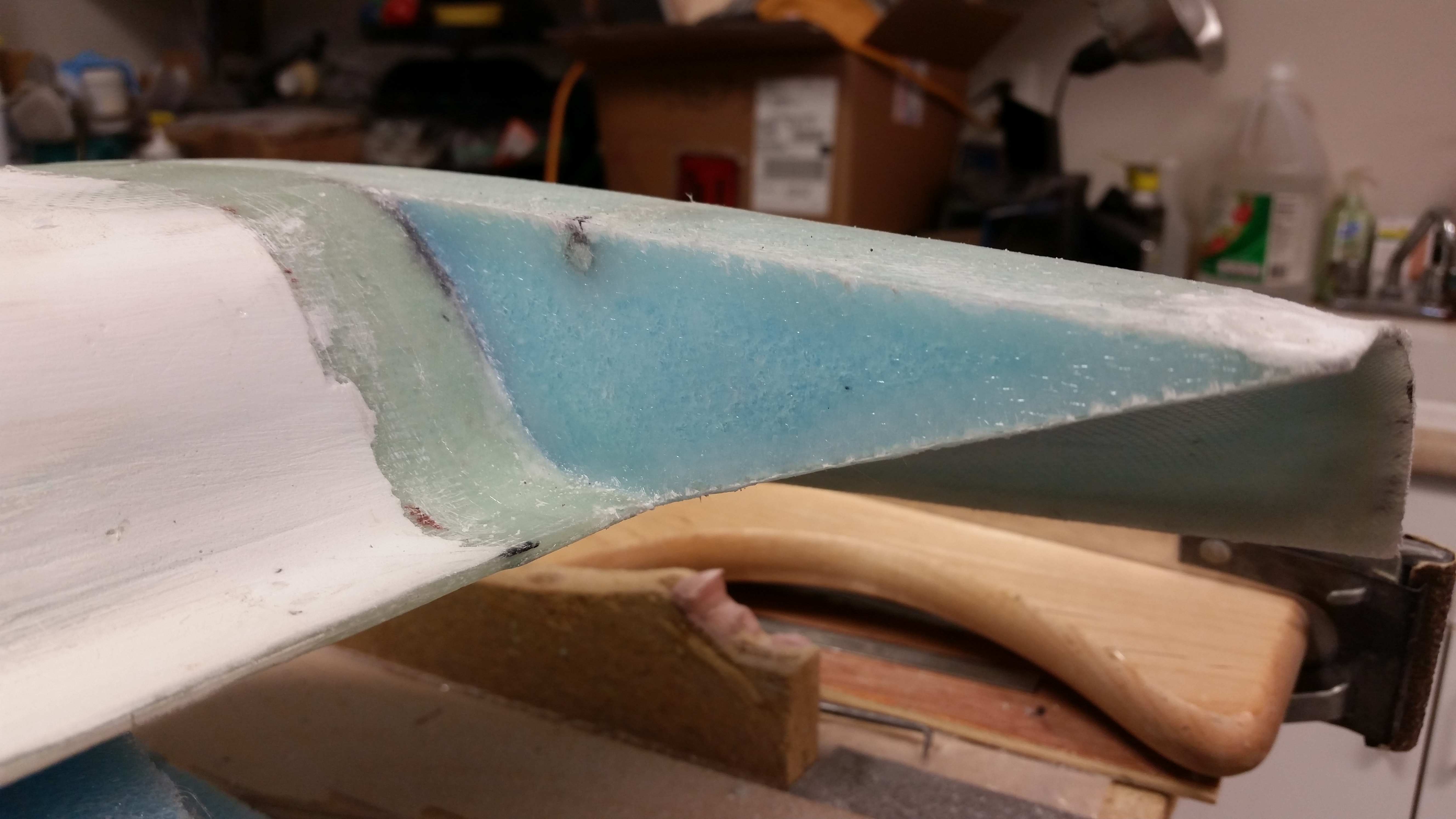
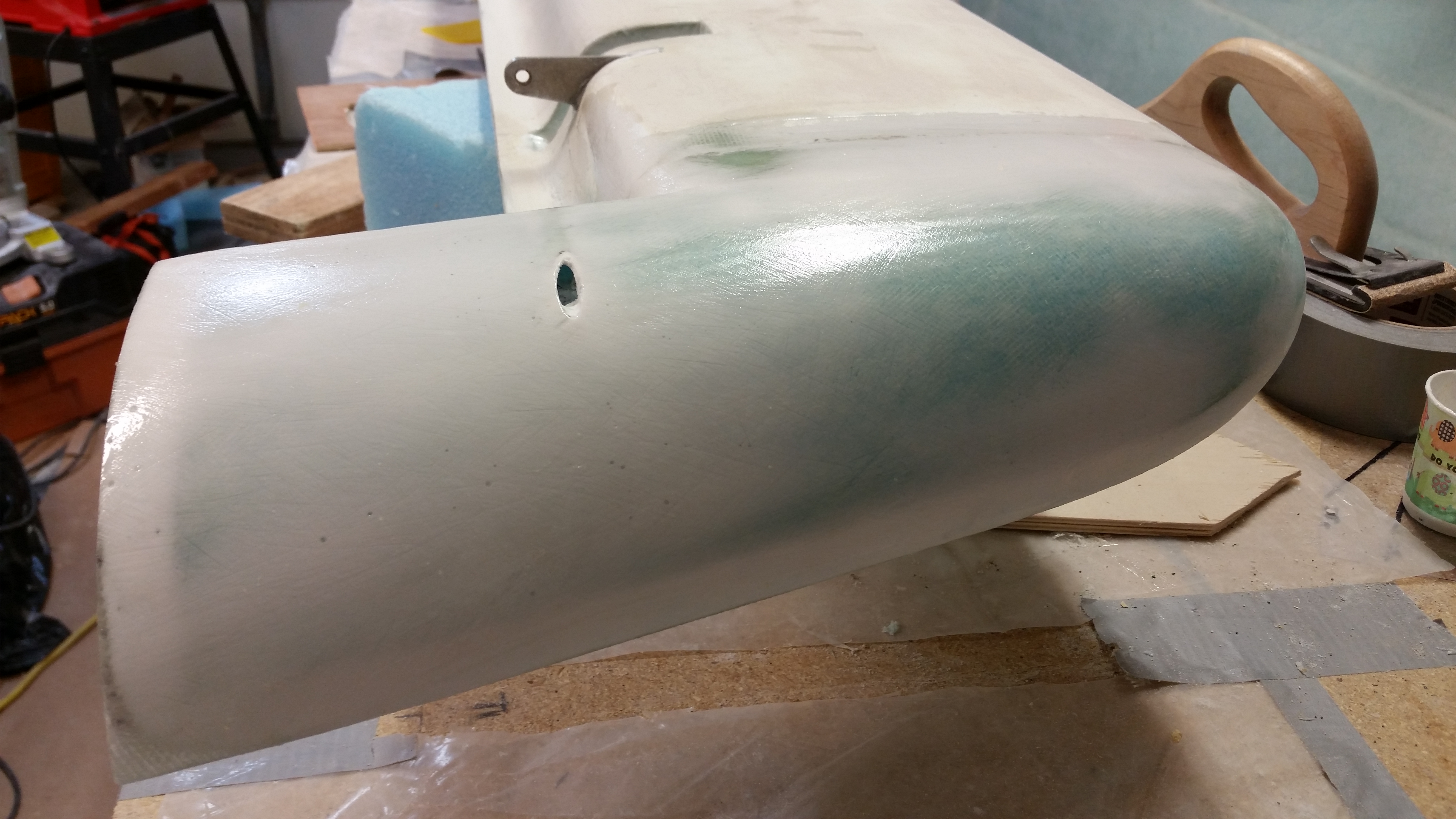
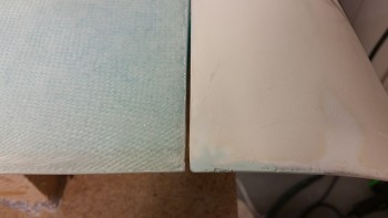
As per Wayne Hicks, and so many other Canardians, I decided that the easiest, less-destructive route for prepping the surface of this plane for finishing would be sand blasting. It’s faster and clearly it can prep the fibers that lie slightly below the surface as compared to the “taller” fibers without having to destroy the strength & integrity of the outer fibers–as one would have to do if sanding the surface in preparation for finishing.
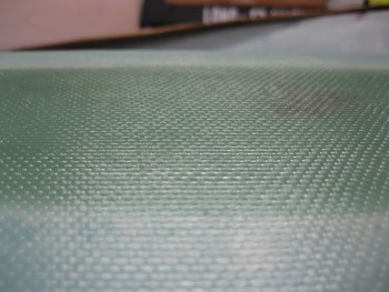
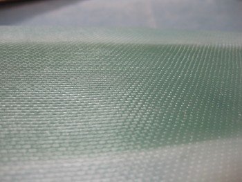
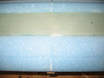
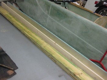
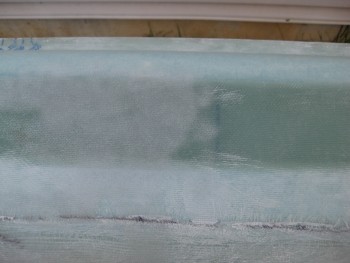
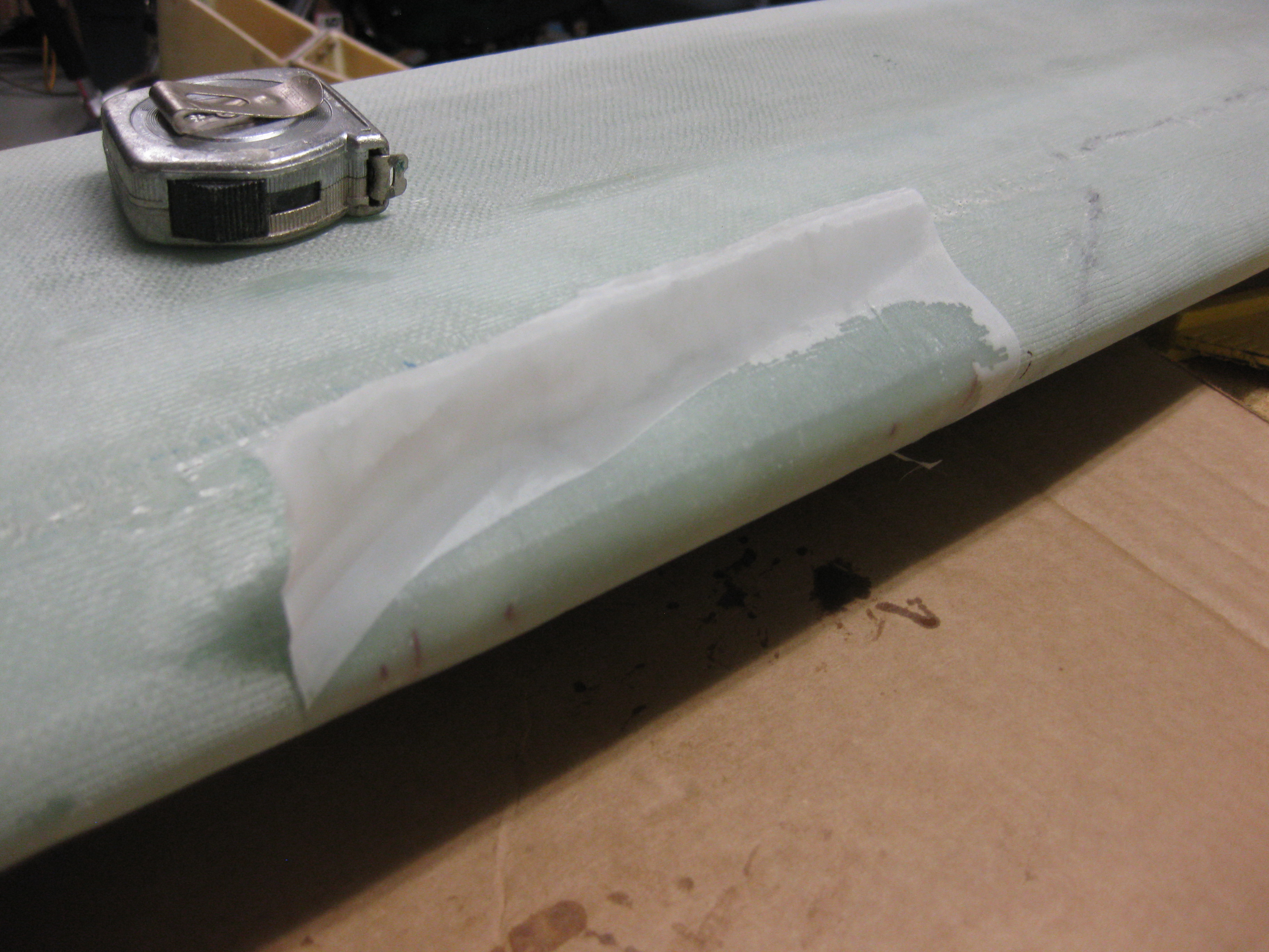
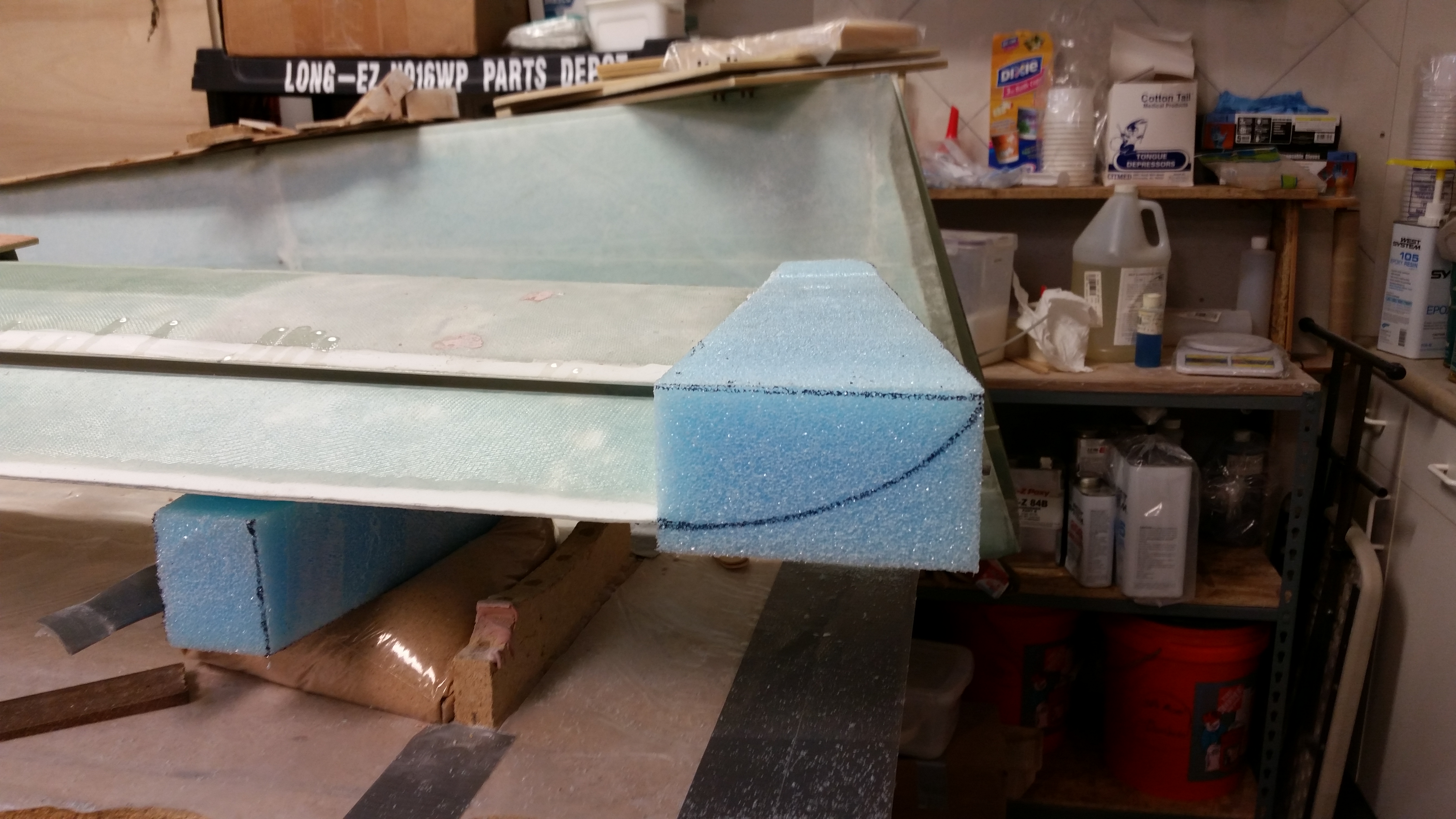
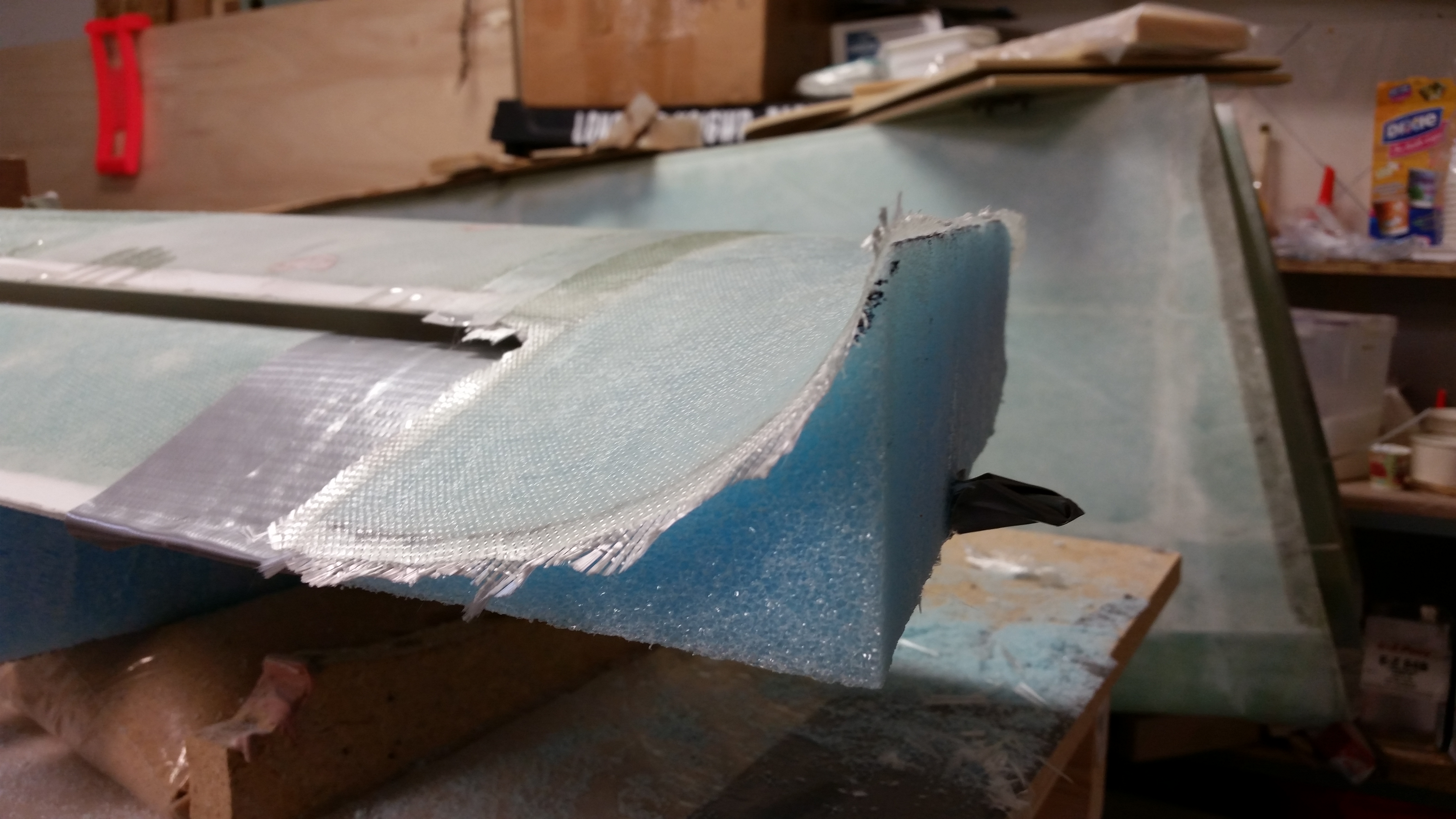
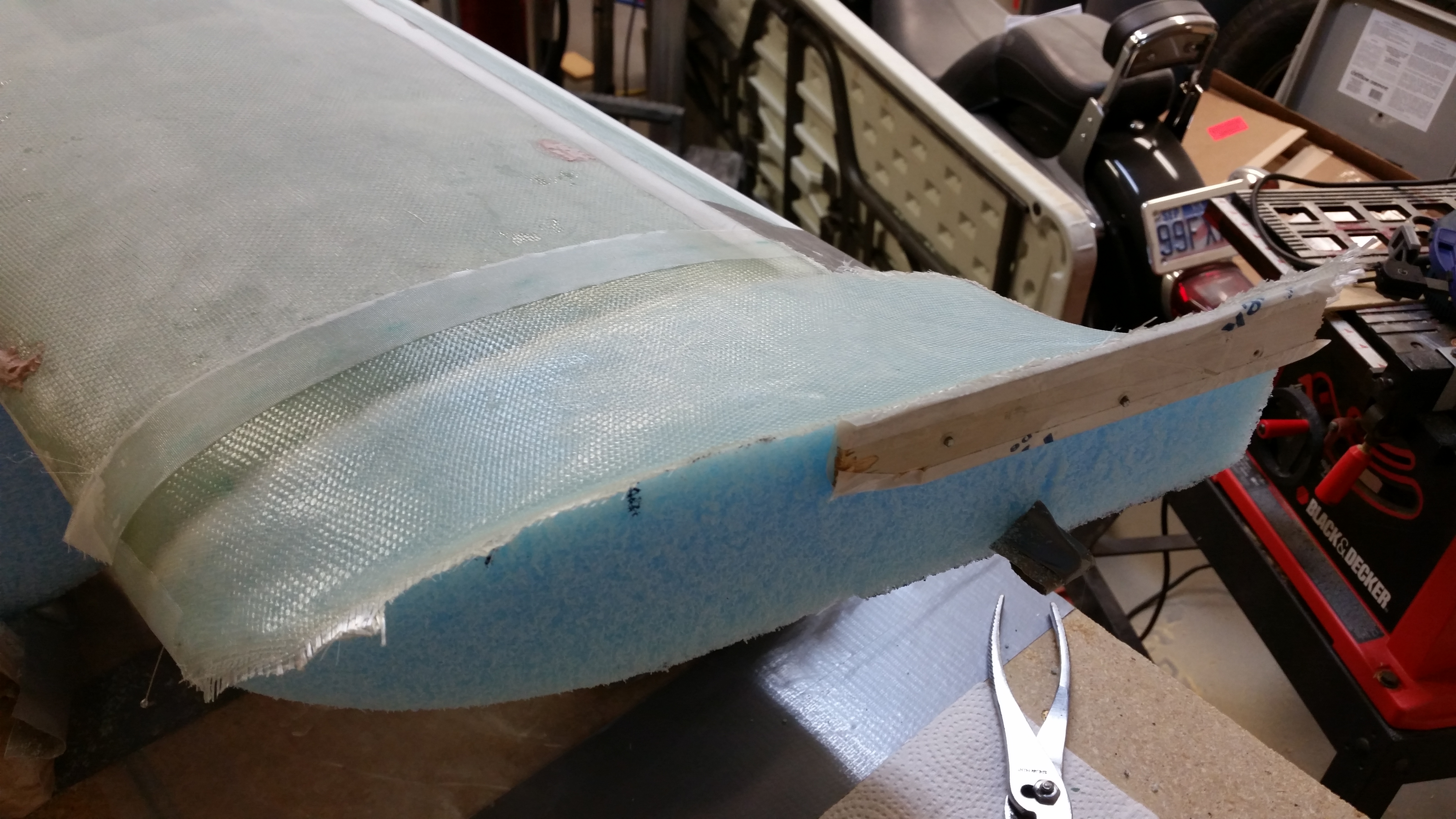
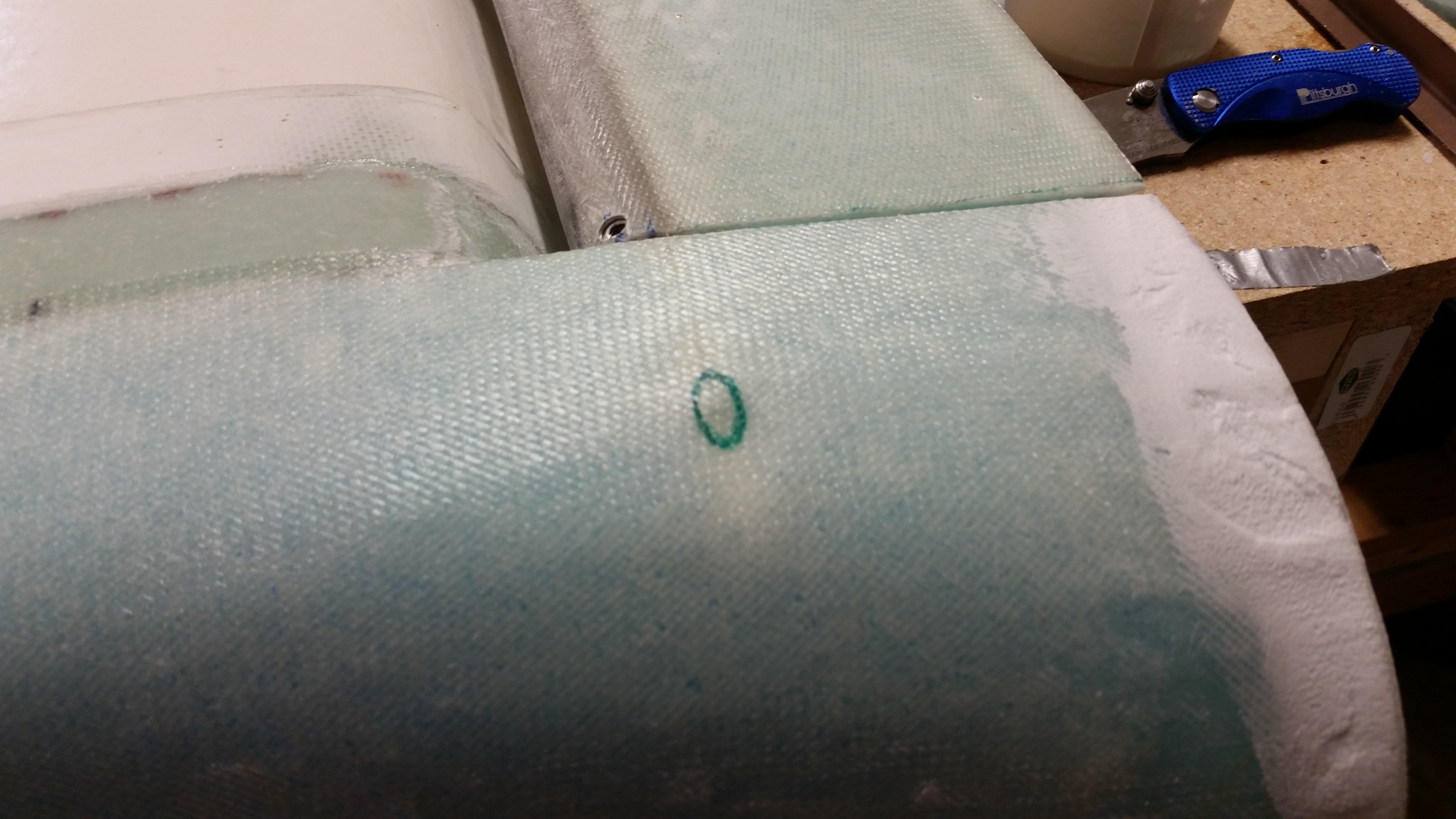
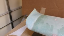
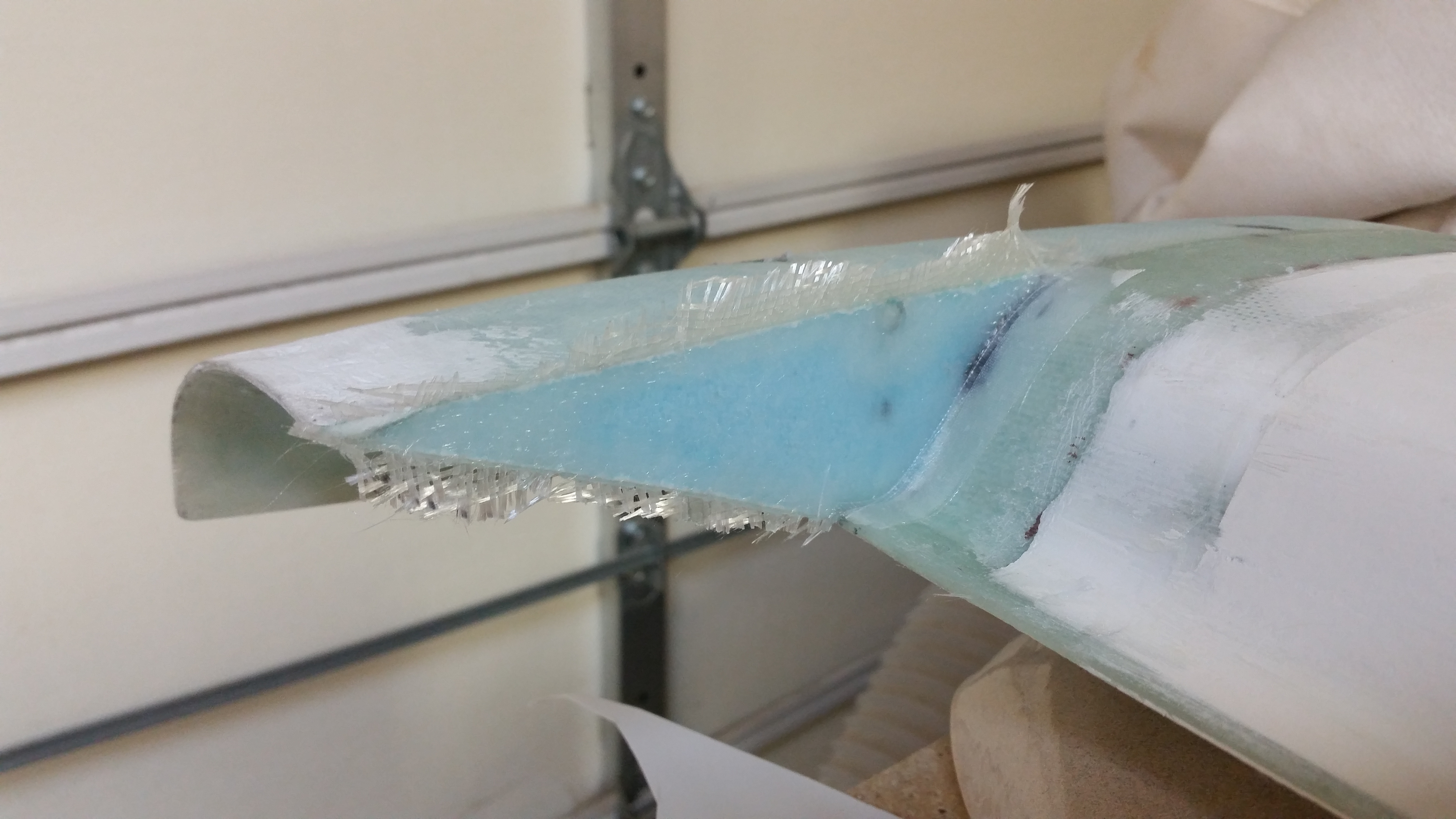
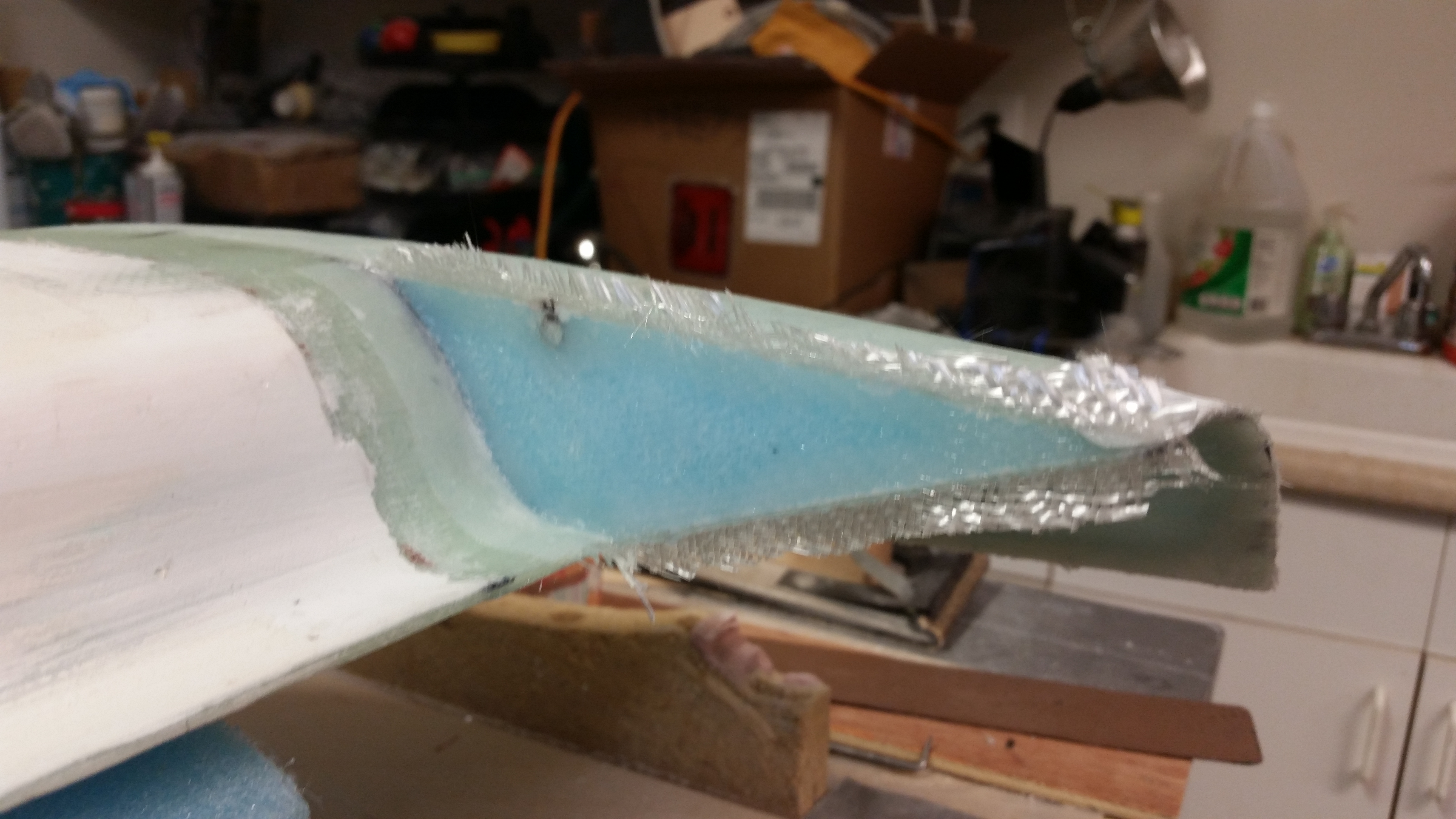
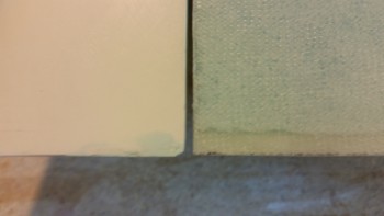
I personally find the texture, gleam & appearance of well laid-up glass (above) wonderful, as I’m sure a lot of other folks that work with fiberglass do as well. But of course this surface can’t remain for the final finish, so we must often cover up some of our best work (and thankfully our not-so-best!) under micro!
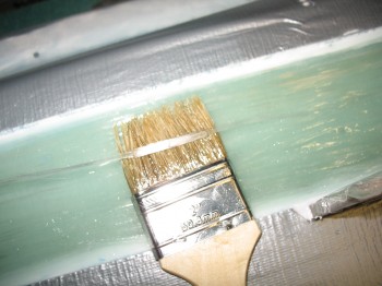
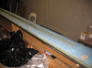
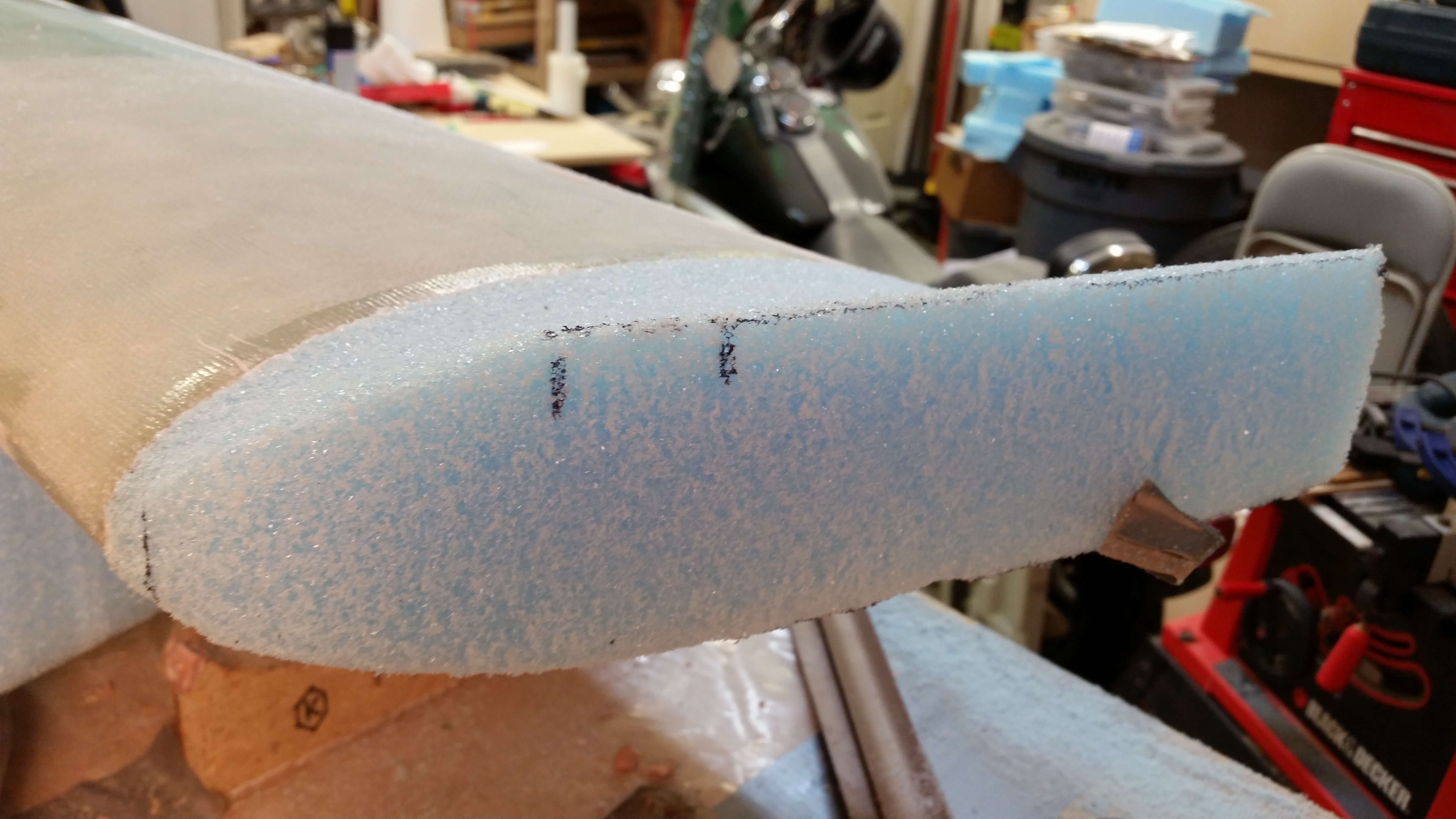
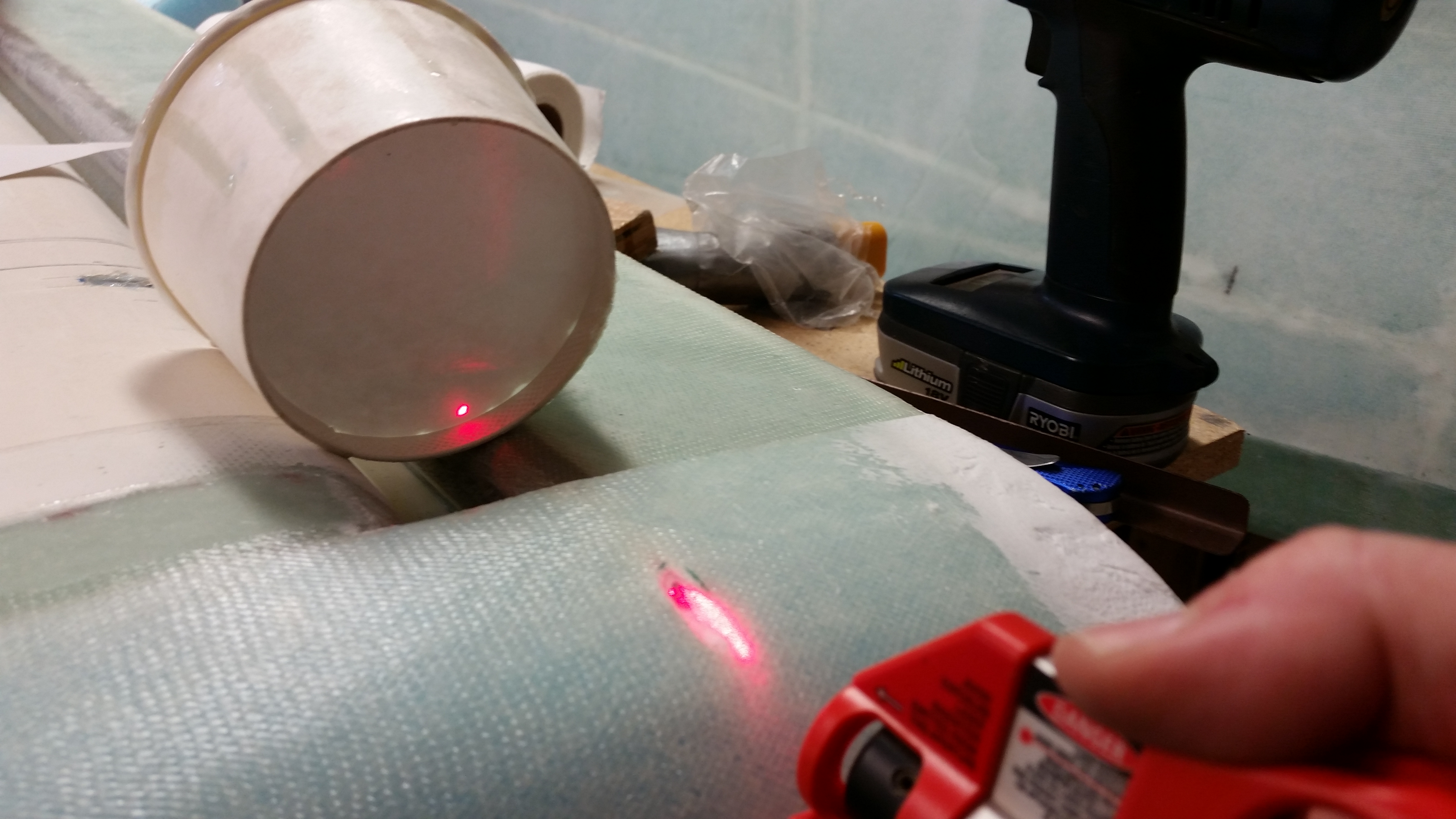
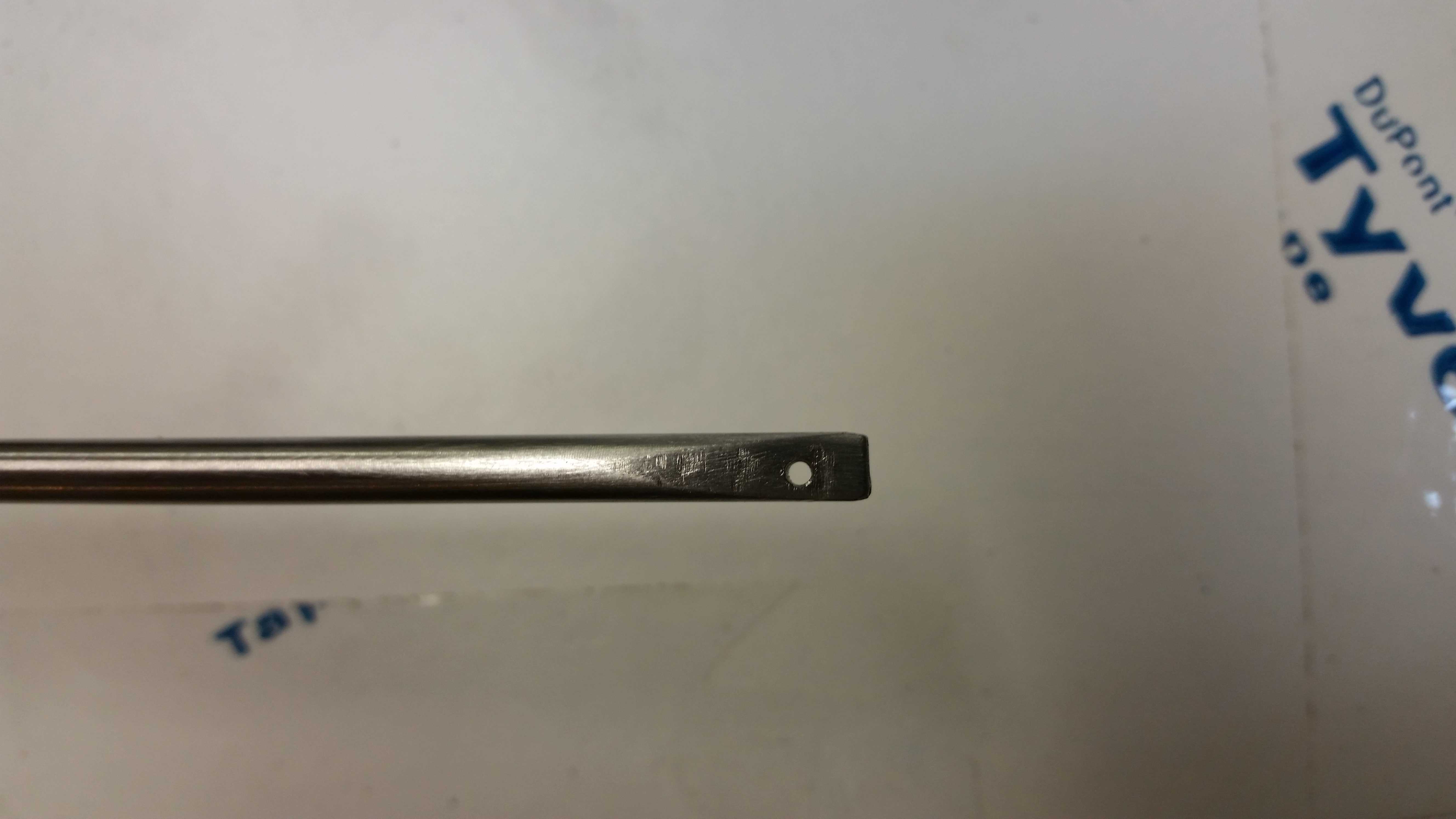
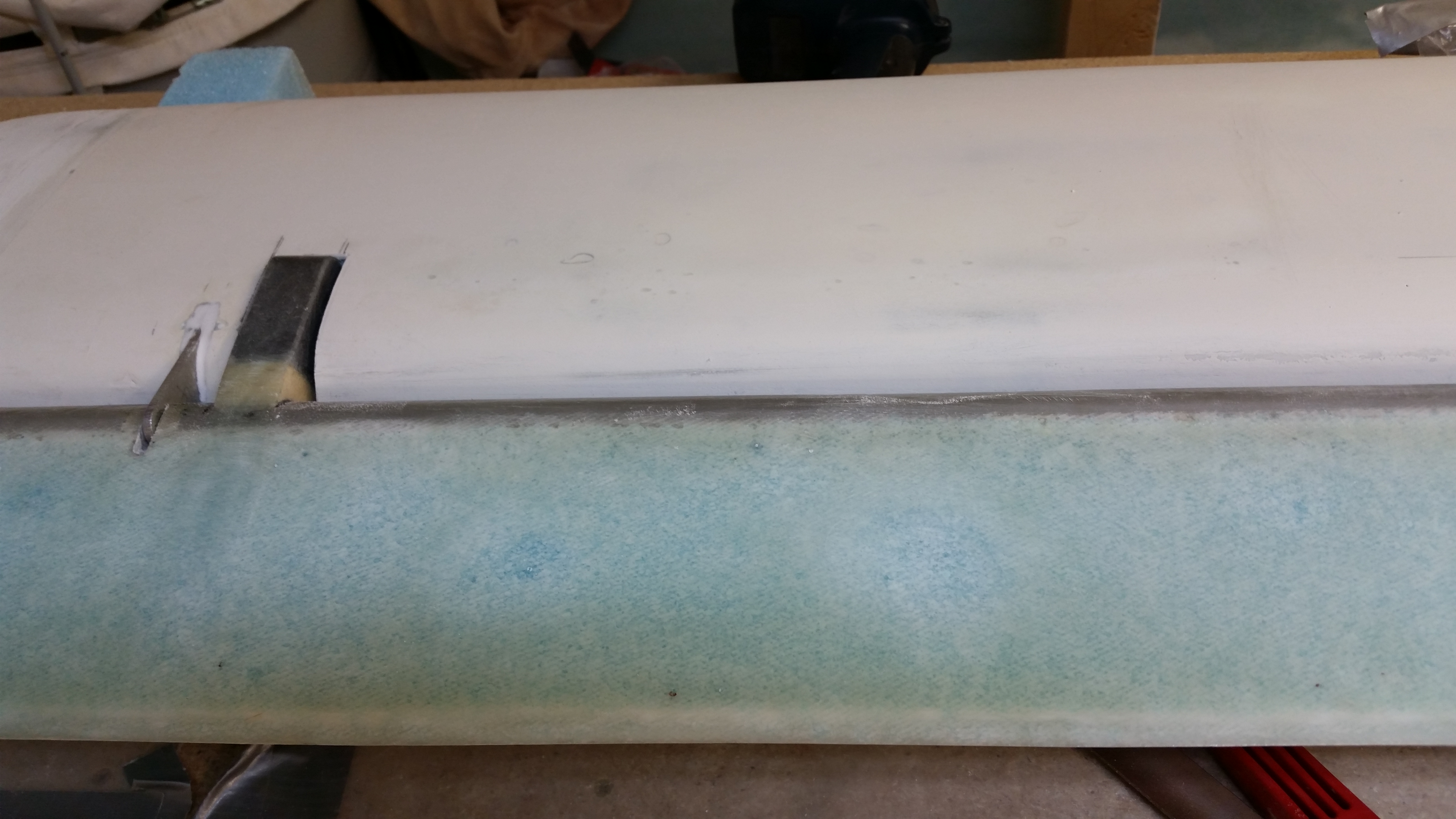
I wanted to add this shot below for my fellow builders who don’t use MGS. I still am impressed by how a line drawn on the shear web can still be seen after ~10 plies of 3″ UNI tape have been laid up over it. As a user of MGS, it will be especially interesting to finish the surfaces of these “transparent skinned” components into a solid-colored airplane.
As I’m sure most of you are aware, I had some definite sandblasting woes when trying to sandblast the rollbar before priming it. I have since done a lot of research and am hoping that I can get this sandblaster to work well enough to finish at least the canard, then I can reassess.
I started by taping up the antenna leads to protect them from any errant sandblasting.
I then did the same for the canard mounting tabs.
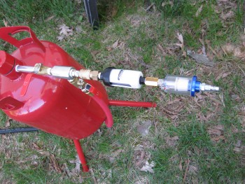
One issue that I wanted to avoid that was a possible contributor to my sandblasting woes was ensuring that the air I was using was CLEAN & DRY. I bought & employed a couple of inline filters & combined them with the appropriate air connectors into an assembly that I jokingly called, “the Kraken.” I then mounted the Kraken to the air inlet on the sandblaster.
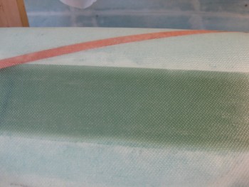
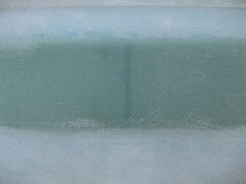
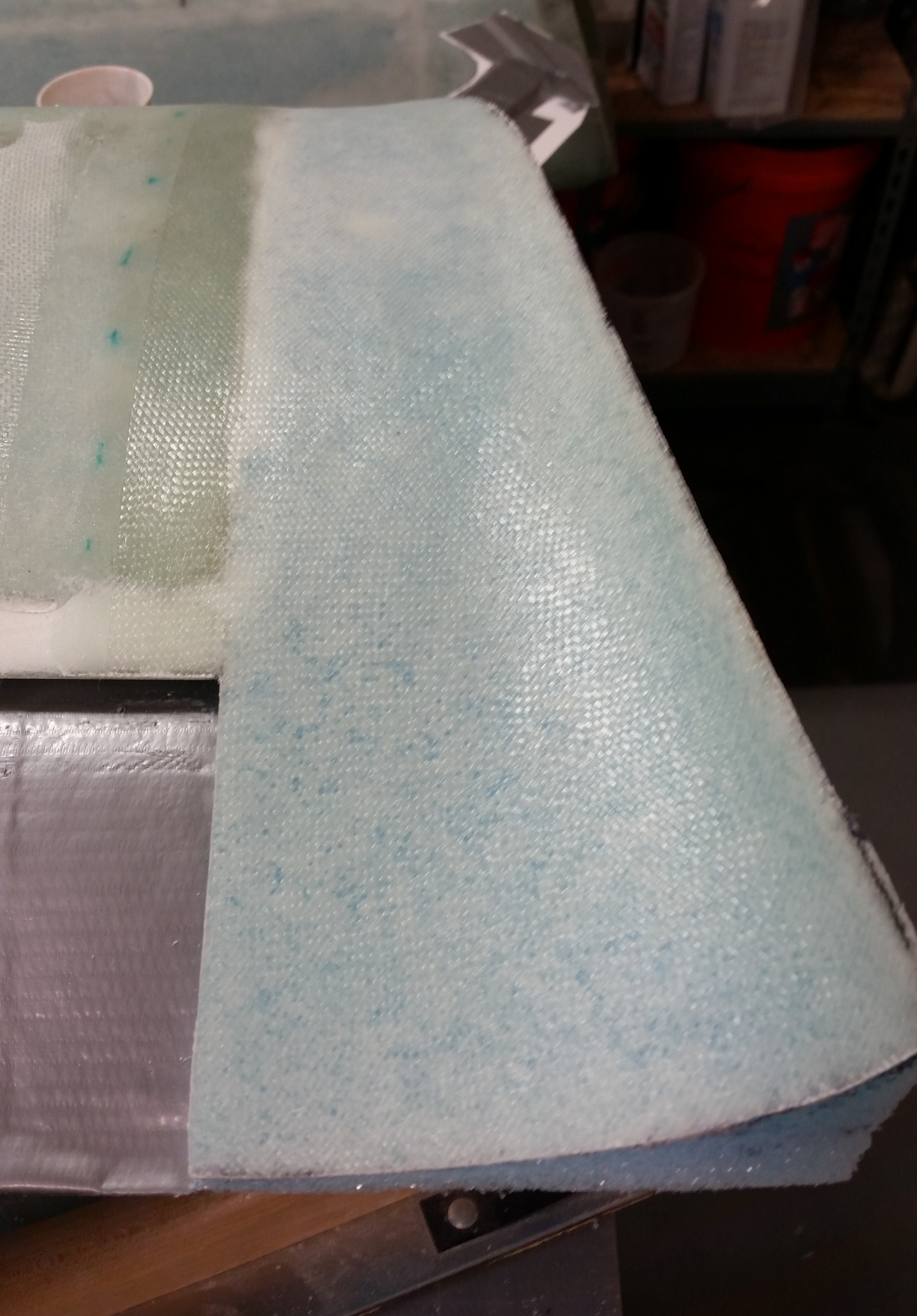
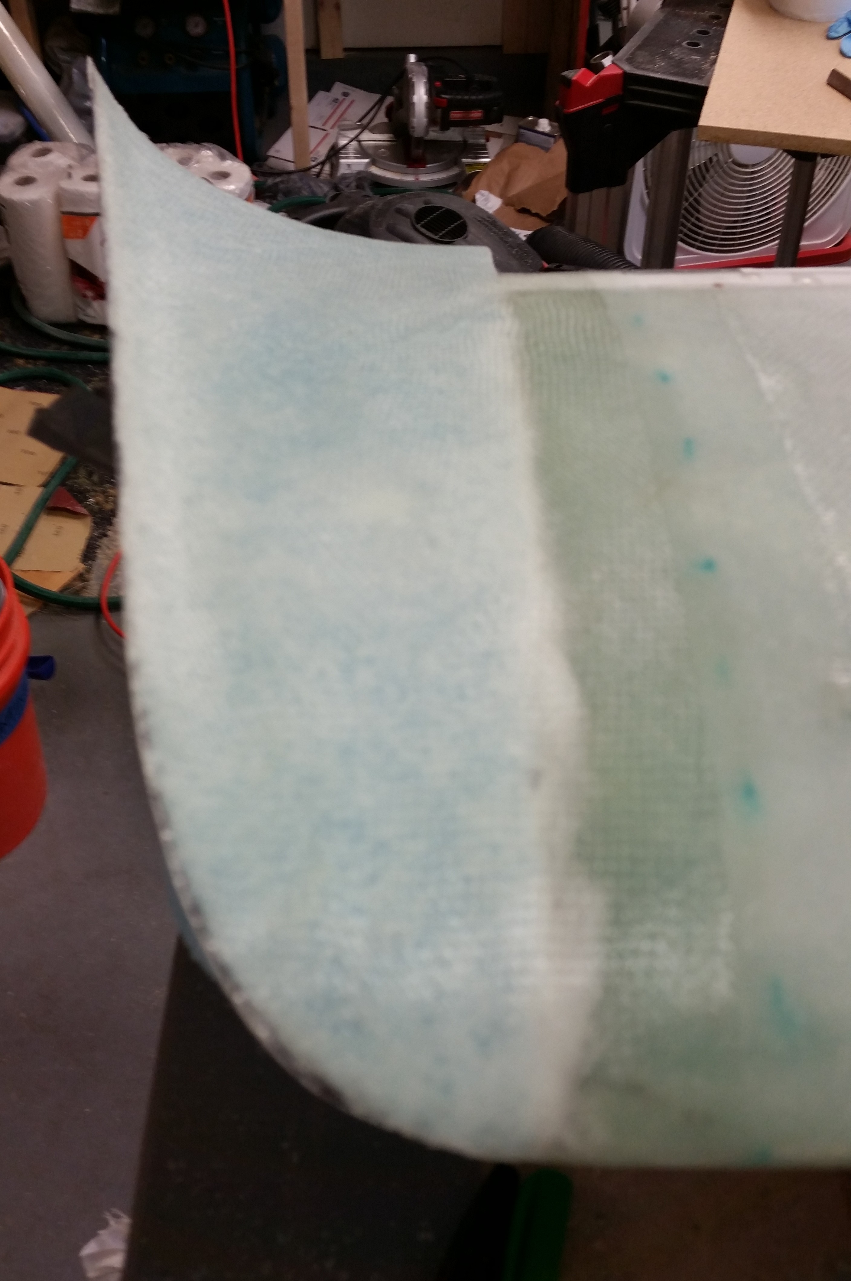
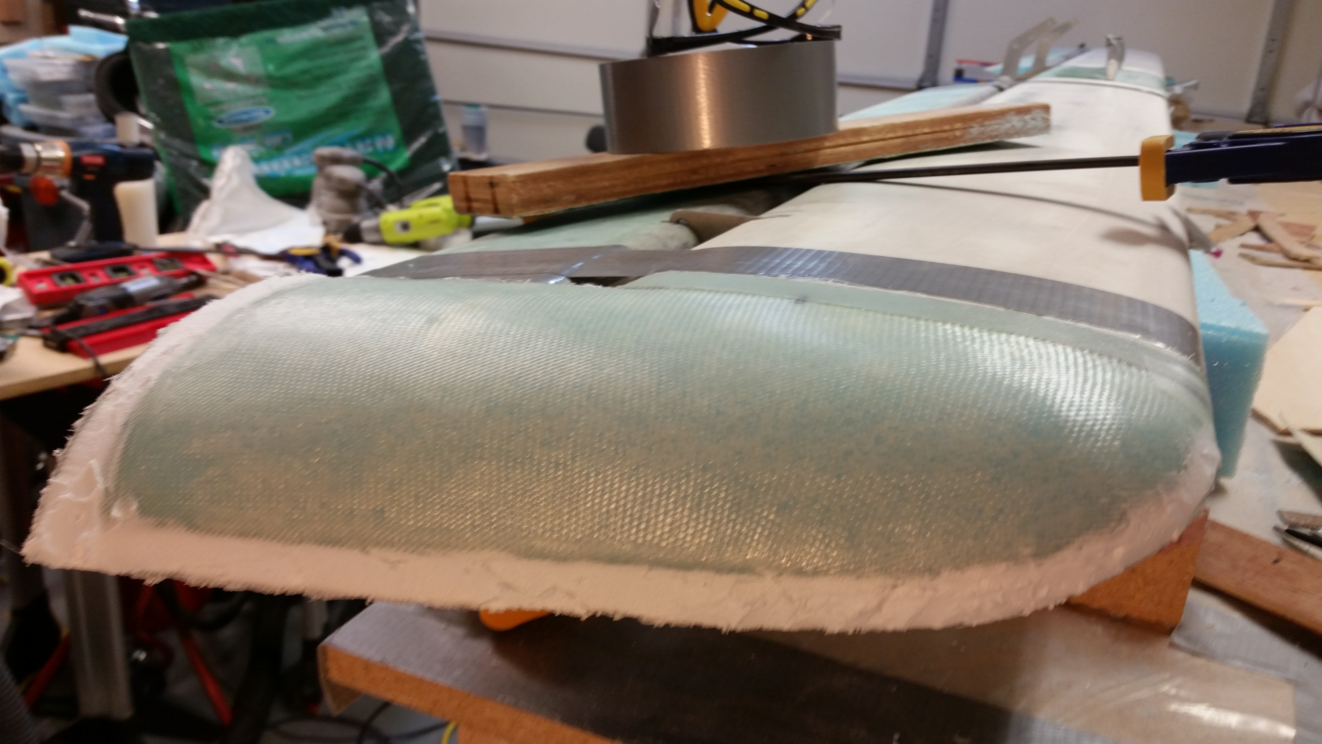
I then employed all the tips, tricks & processes that I had learned about this somewhat cheap sandblaster, and although it’s still not a pleasure to use, it at least gets the job done now. You can definitely tell the areas that were sandblasted & those that weren’t.
Just as Wayne Hicks described his sandblasting experience on his Cozy IV build site, the sandblasting textured the canard surface perfectly and didn’t damage it in any perceptable way.
Thus, stopping every few minutes for both the compressor to re-build up pressure, and clearing out the subsequent plugged-up nozzle from the decrease in pressure, I was able to knock out the bottom right side of the canard in about 40 minutes. With a bigger, higher quality sandblaster I’m sure I could have cut that time in half, but I’m more than happy with the time, effort & cost required to attain the results that I did.

Another technique I employed in optimizing the sandblaster’s ability to simply work was to bring my compressor out to the job site. Instead of running 2 lengths of air hose, I simply used one. The first time around I used 2 hoses, with one of them being rubber. Apparently rubber hoses allow much more moisture buildup, as does longer lengths of hose.
So somewhere in both using the correct sequence in the opening of the 4 valves on the sandblaster, and the corrective measures I took to ensure clean, dry air, I was able to sandblast the entire bottom side of the canard.
At one point fairly early on, I did have to empty the sandblaster of all the media and fill the sandblaster hopper with smaller amounts to keep it from clogging up. But again, that was a minor annoyance in comparison to being able to sandblast this thing on the cheap.
Since it started getting dark, on the topside of the canard I simply sandblasted the edges at the inboard areas where I will need to finish the canard, and the glass covering the outboard extensions which need surface prep for the upcoming glassing of the “swoosh” tip extensions.
All the sandblasting I accomplished today on the canard actually meets all my requirements for completing chapters 10 & 11. However, I will finish sandblasting the top of the canard since as I mentioned before, my plan is to actually finish the entire canard & elevators to paint.
•••
1 October 2015 — Yesterday and today I’ve been pouring over my project to-do lists, plans and tasks in order to get back on track with the build. After spending hours re-covering specific steps in the Long-EZ Plans Chapter 10, the Roncz canard plans, and the Cozy Girrrls instructions on their elevator actuators, I then went back over my notes on finishing the canard with micro, sanding techniques (mainly Wayne Hicks’ methods), etc.
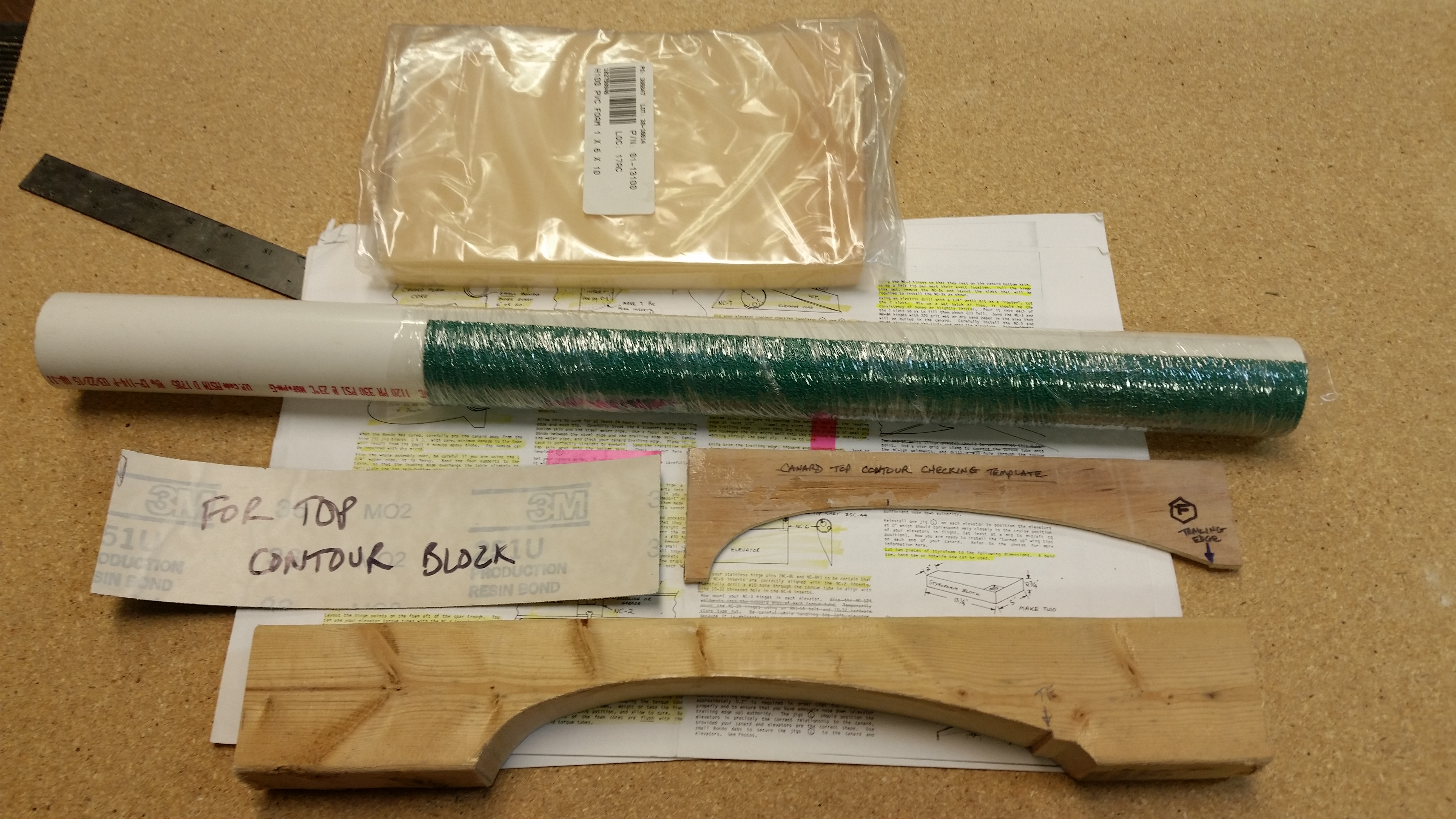
My first order of business, after cleaning & organizing the workshop a bit, was to find all the templates related to the canard and elevators. That took maybe 5 min since luckily I had the box in which they resided in sitting on the work bench. Hey, sometimes I guess I am a little proactive!
My next task was to clean all the goop off the “K” canard mounts to allow them to be reused while finishing both sides of the canard. I spent about 15 with a razor knife cleaning up the crud to allow for a fresh clean canard mounting.
After calculating the distances between the 5 “K” mounts I’m going to use, I then mocked up the canard upside down on the “K” mounts to ensure a study platform on which to finish the bottom side of the canard.
Now, if you’ve seen Wayne Hicks’ webpage on how to finish the canard, then you’ll know that he uses a 3-4″ wide sanding block which is essentially nothing more than a widened contour template that is adjustable in height and which a wide piece of sandpaper can be attached on the inside of the contoured area. Well, on his site Wayne explains that you can’t finish the bottom of the canard using the contoured sanding block setup because of the multiple installed elevator hinge mounts that get in the way.
So, a few years ago when I was talking to Randi (aka “Cozy Girrrl”) she gave me a ninja tip to finish the underside of the canard first, then not only would I have a more concise measured gap between the aft tail of the canard and the front of the elevators, but I would also have eliminated a lot of pain & strife trying to finish that bottom of the canard with those darn elevator hinge tabs in the way! Plus, not only would the finish look much cleaner & nicer, but it would be more aerodynamically correct. A win-win if you will.
One last thought on finishing the bottom of the canard now, is that as simplistic as it sounds, it will be finished. And since I plan on finishing the entire canard & elevators before storing it away until later, it will be one less thing I have to finish when I “hit the wall” that is Chapter 25 (aka “Finishing”).
The first actual step that I needed to complete was repairing the Leading Edge of the canard. You see, back when I glassed the canard as I was pulling the duct tape off the leading edge after the bottom skin had cured, it pulled out a pretty big chunk of the leading edge blue foam underneath. With the canard being upside down, and with some foam missing under that 4″ leading span, the bottom skin glass naturally depressed a little right in that area as it cured. When I flipped the canard to glass the top, I had to back fill micro behind that 4″ deformed area on the LE to account for the missing foam.
When I did the glass layup on the top of the canard, I could tell that I was going to have to repair that damaged LE area later on by adding a few plies of glass. To “mark” the LE area that would required repair, I simply peel plied it. The peel plied area on the LE was thus my marker for the future on the exact area that needed further work.
Well, the time to repair the canard LE has finally come . . . after about 2-1/2 years since I finished the canard. (Wow, time flies!)
I took a straight edge to the front of the canard to get an idea of how much glass to add. I determined I would only add two plies of BID: a) 3/4″ x 4″ and, b) 1-1/2″ x 5.2″. These would give me just enough glass fill that, after sanding, the remaining surface irregularities would easily be filled by the finishing micro.
As per my usual, I will pre-preg this layup so I cut out a small piece of plastic and prepped my peel ply.
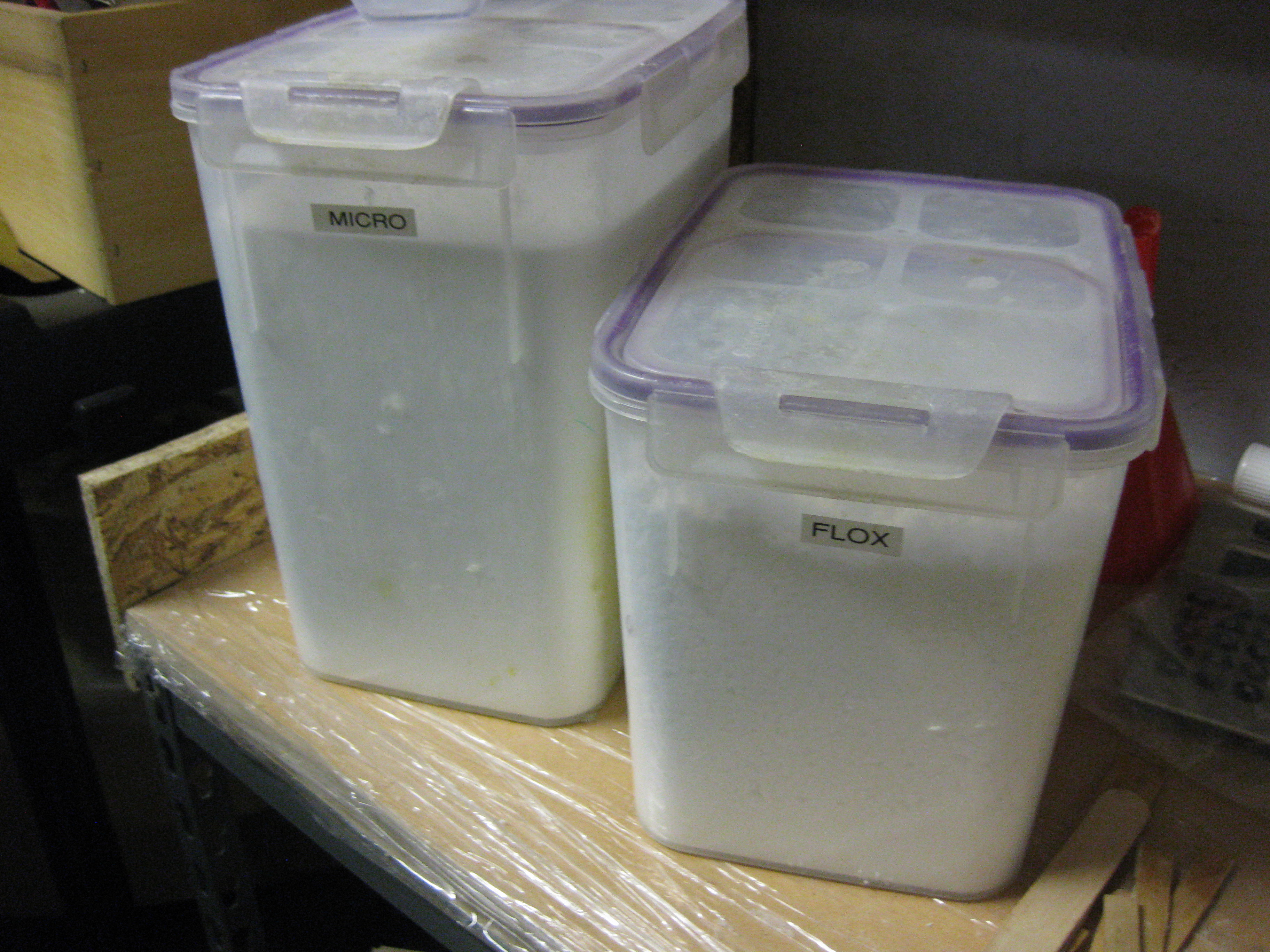
Before getting started on my new build quest, I had to reload both my stock of micro and flox, each container being almost completely empty!
Below is the freshly laid up 2 plies of BID.
 Below are a couple shots of the finished layup peel plied.

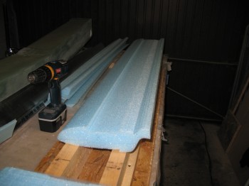
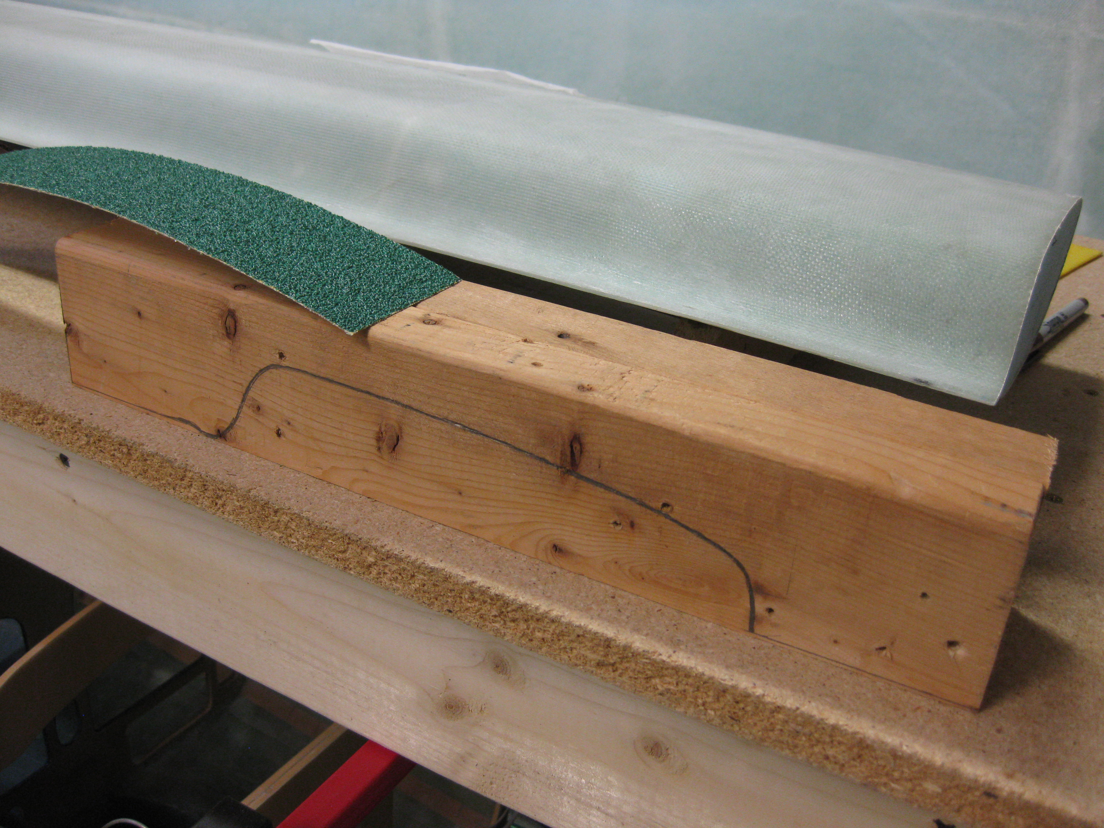
As the LE patch cured, I started working on the canard lower contour sanding block.
A few hours later I pulled the peel ply off the 2-ply BID patch.
And then tested the patched LE area against a straight edge. There are still a few minor irregularities, but nothing that can’t be handled with a little bit of sanding and some micro during the finishing process.
•••
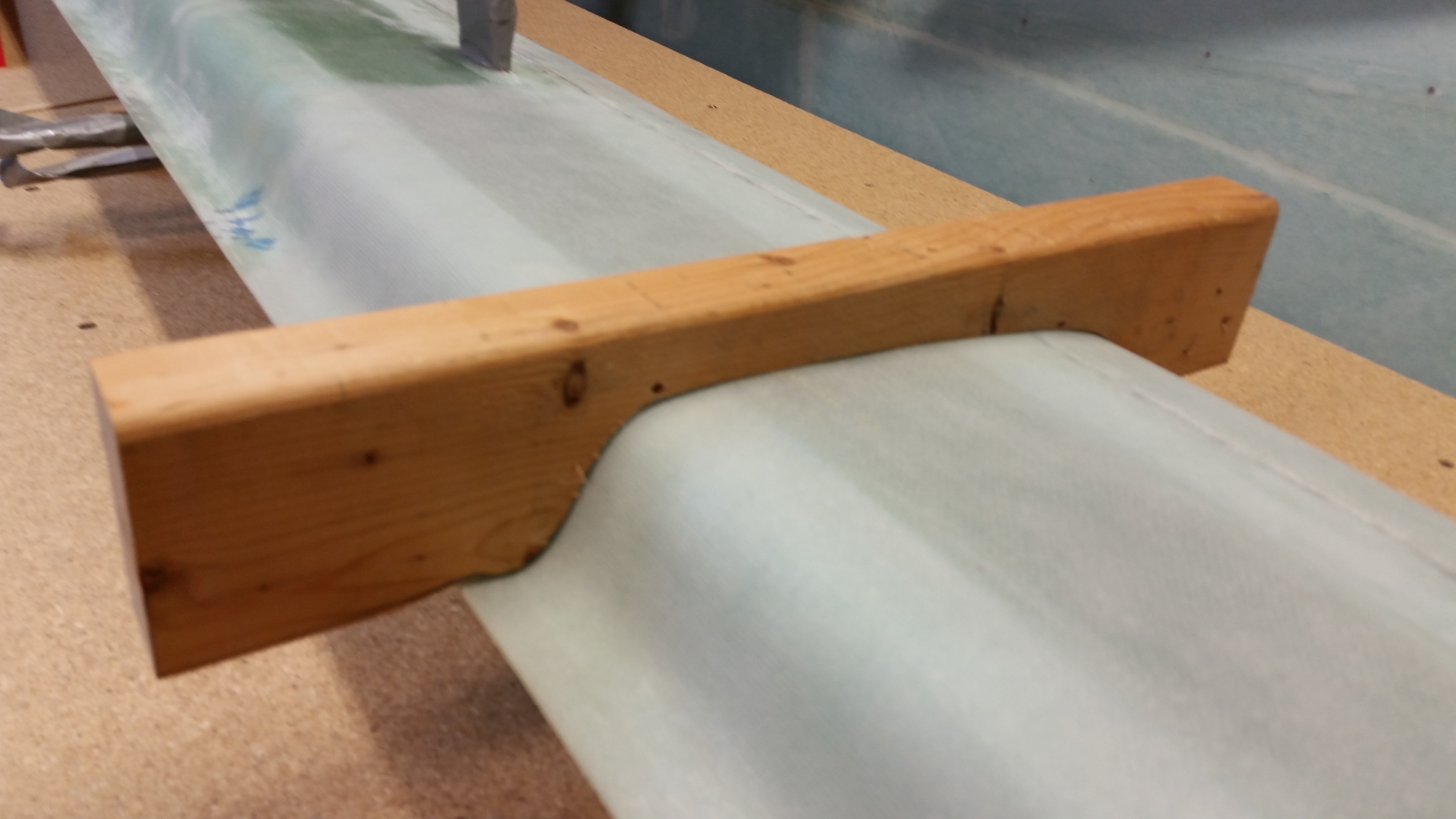
2 October 2015 — This afternoon was all about making the sanding block for finishing the underside of the canard. As I described before, this sanding block is nothing more than a 2-3/4″ thick version of the “F” contour template for the Roncz canard.
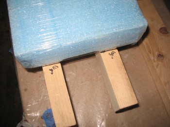
Yesterday I showed a quick pic of the results of my grabbing a 2×4 out of my scrap pile and tracing the “F” contour template on it. Once the outline was traced, I used a dull pencil to retrace the line to allow for the actual thickness of the sandpaper once attached to the contour sanding block. BTW, Wayne Hicks used wider sandpaper than I will be using, but since all my 4″ wide sandpaper is attached via velcro, and my narrower 2-3/4″ sandpaper strips are attached via peel ‘n stick, I figured I would go with the cheaper/narrower peel ‘n stick to start out. If need be, I’ll change this later on.
Again, yesterday I cut two pieces of a scrap 2×4 to length, and then ripped one of them lengthwise to get the correct width, once the two 2×4’s are joined, to match the sandpaper width.
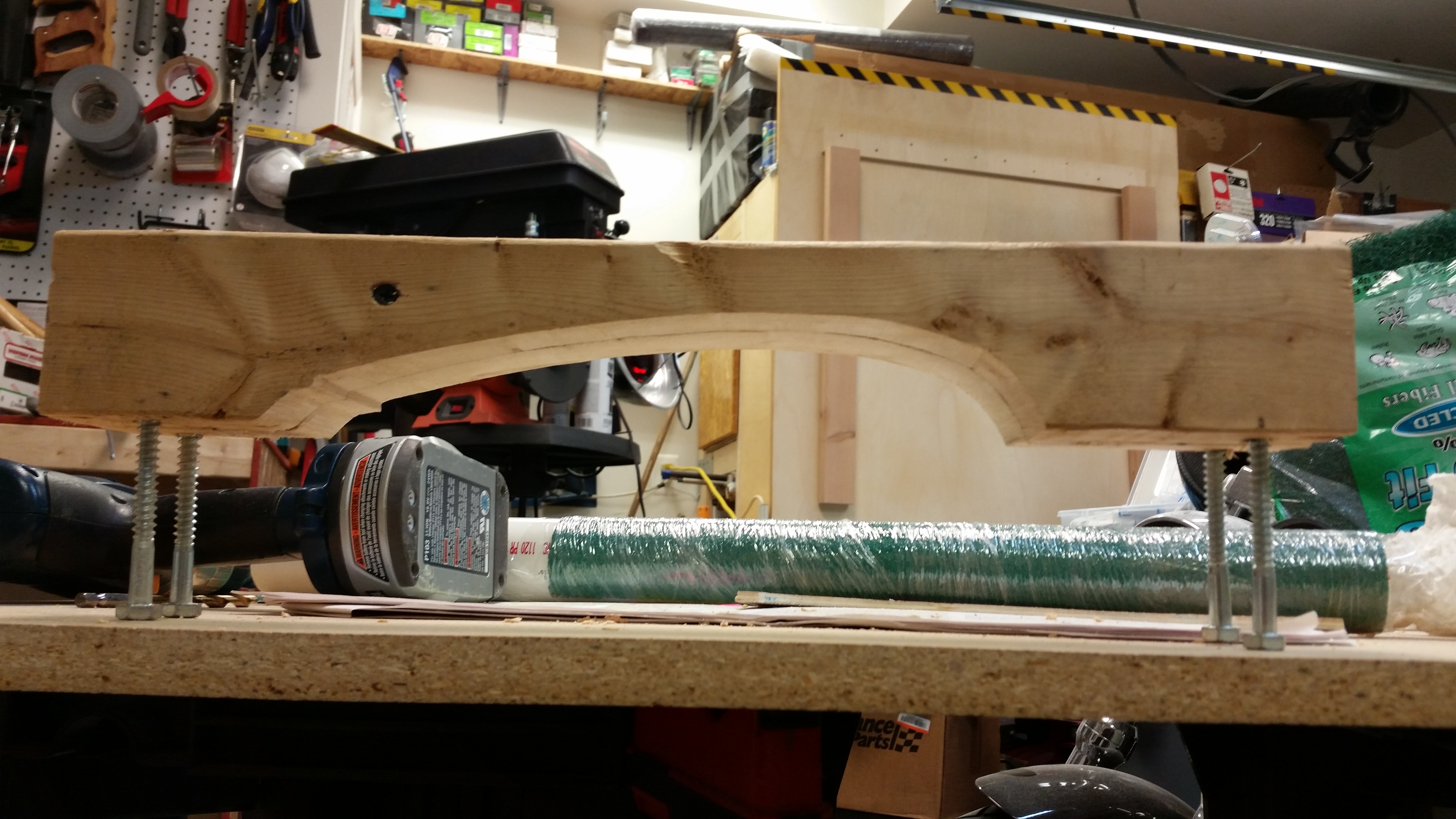
Today I clamped the 2×4 pieces to my “new” table saw as a work bench and used my jig saw to cut the contour profile. [SIDE NOTE: A friend of mine called me up & asked me if I wanted this table saw as she was getting rid of it because sadly her dad passed away. I was wanting a cheaper table saw to use to rip the metal engine mount extrusions since I was really not comfortable doing this on my nicer table saw. I tested this table saw on these 2×4’s, and so far it works like a champ.]


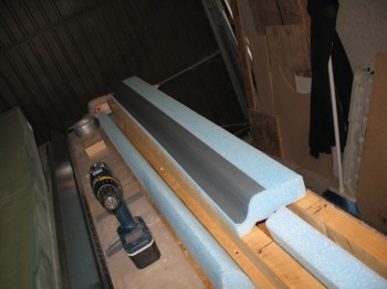
Here’s the result on 2×4 piece #1:
I then transferred the outline of the first (narrower) 2×4 piece to the second 2×4.

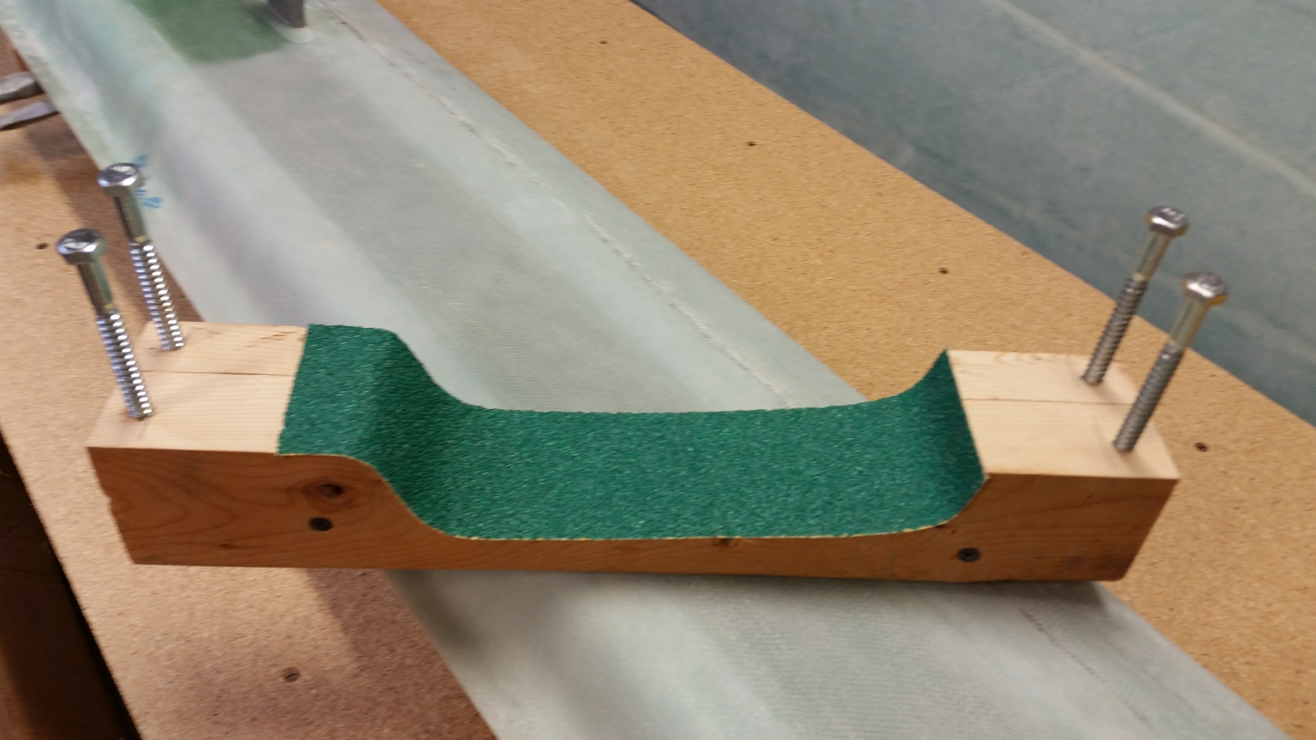
After the profile shape was cut into 2×4 #2 I then clamped the two sides and screwed them together. I then cut and attached a piece of sandpaper to the contour of the sanding block. With the shop at about 70 deg F, I noted the sandpaper was having trouble sticking to the more curvy parts of the contour. I used the heat gun to warm up the sandpaper’s adhesive backing a little, but even after that I’ve come to the conclusion that I will probably have to use 3M 77 adhesive spray to really get it to stick.
Hmm, maybe a good argument for using the velcro-backed sandpaper?
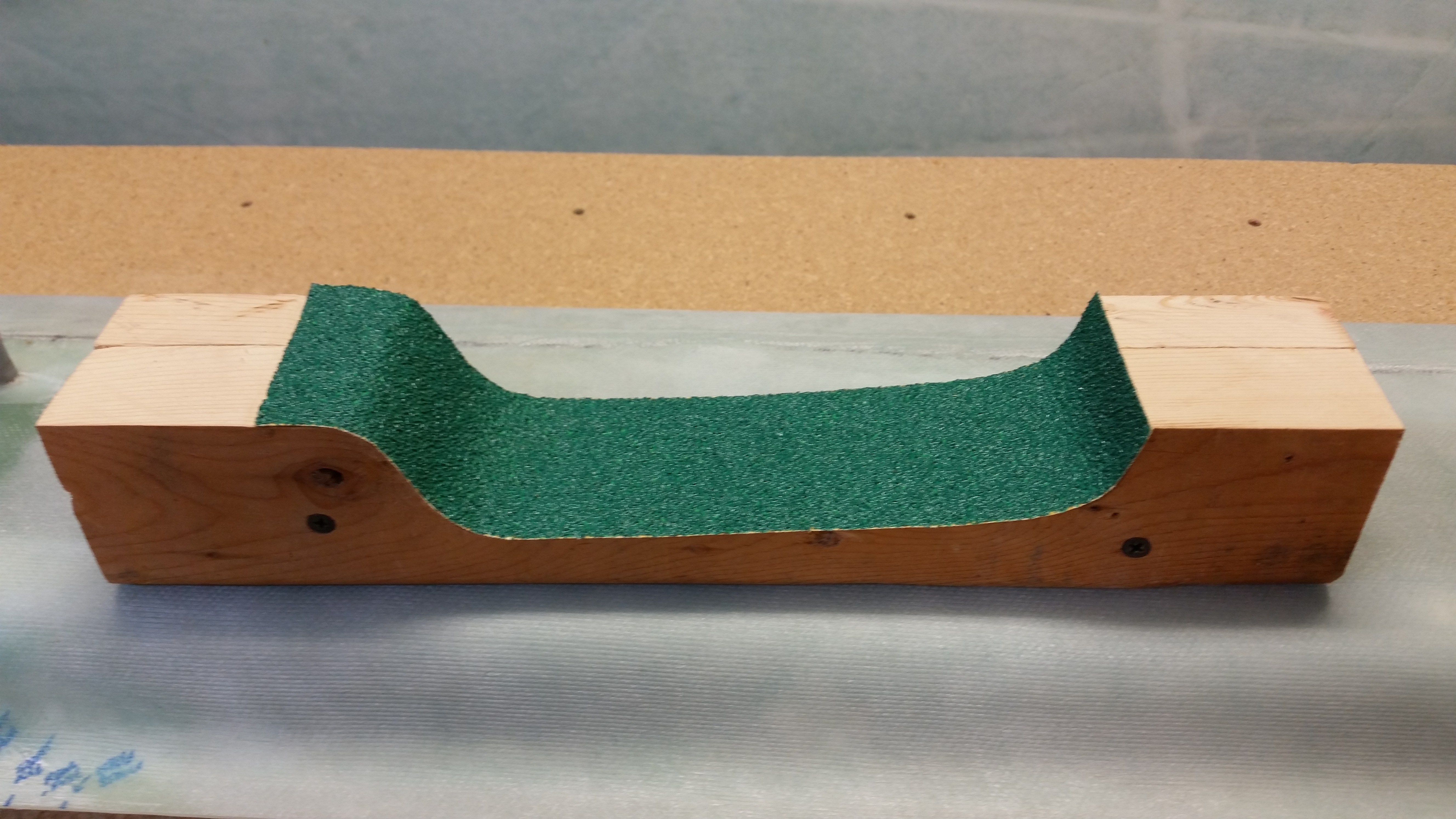
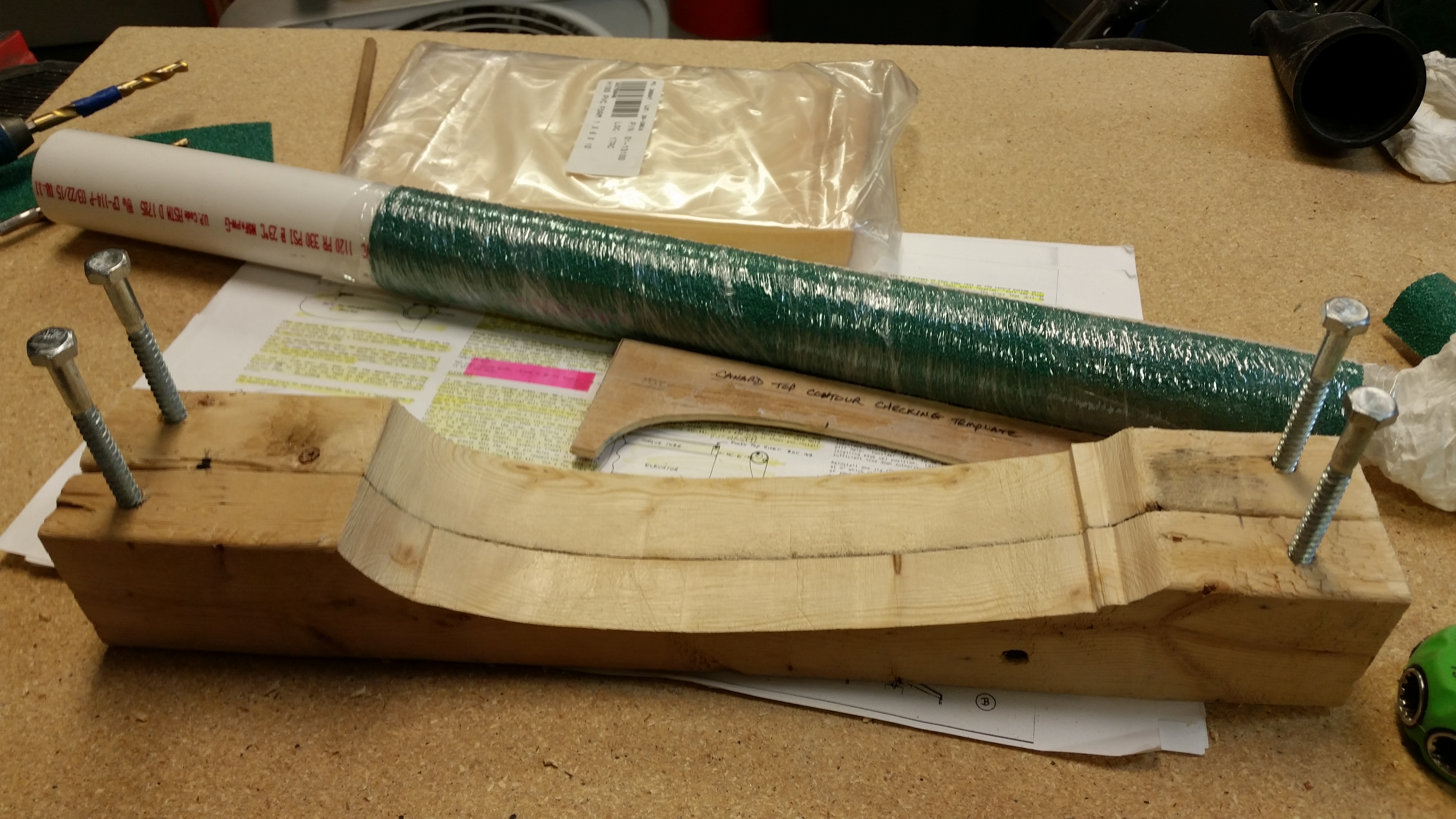
Here’s a shot of the finished product sans “legs”.
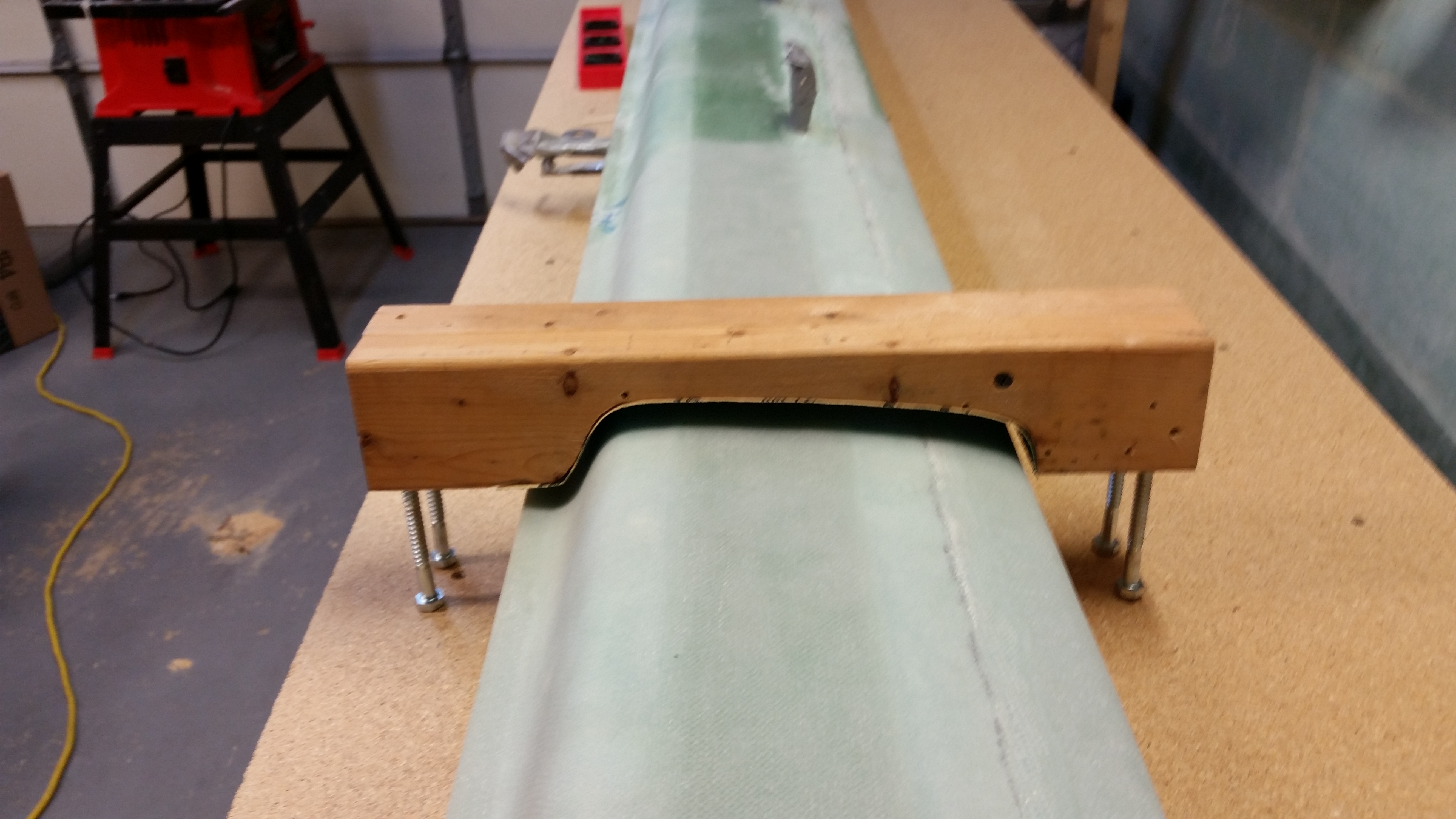
To give this project some legs (yuk, yuk), I drilled a pilot hole in each corner and screwed in a 5/16″ lag screw (I think… don’t quote me on actual size since they were merely sitting there conveniently in my tool bin). Each lag screw is 3-1/2″ long which will be good for the starting height I’ll need once the canard is mounted.
And here’s a quick shot of the finished contour profile sanding block for the underside of the Roncz canard. Tomorrow, I plan on hard mounting the canard to the table and “K” blocks and then getting to work on finishing the bottom of the canard.
In prep for finishing the bottom of the canard, I marked the canard about 1.2″ inboard of each end to show me the point where I need to stop the micro finish on the lower canard surface. The reason for this of course is that the Roncz canard swoosh tips require 1″ of glass overlap onto the canard ensure that they’re solidly attached.

•••
3 October 2015 — Early afternoon I went to Home Depot to pick up some supplies to start the micro finish on the bottom of the canard.
Shortly after I returned home, I met future Long-EZ builder, Sohail, and showed him around my shop, and all the various pieces parts of my Long-EZ project. Of course what ensued was a long conversation on building Long-EZ’s, canards, and airplanes in general.
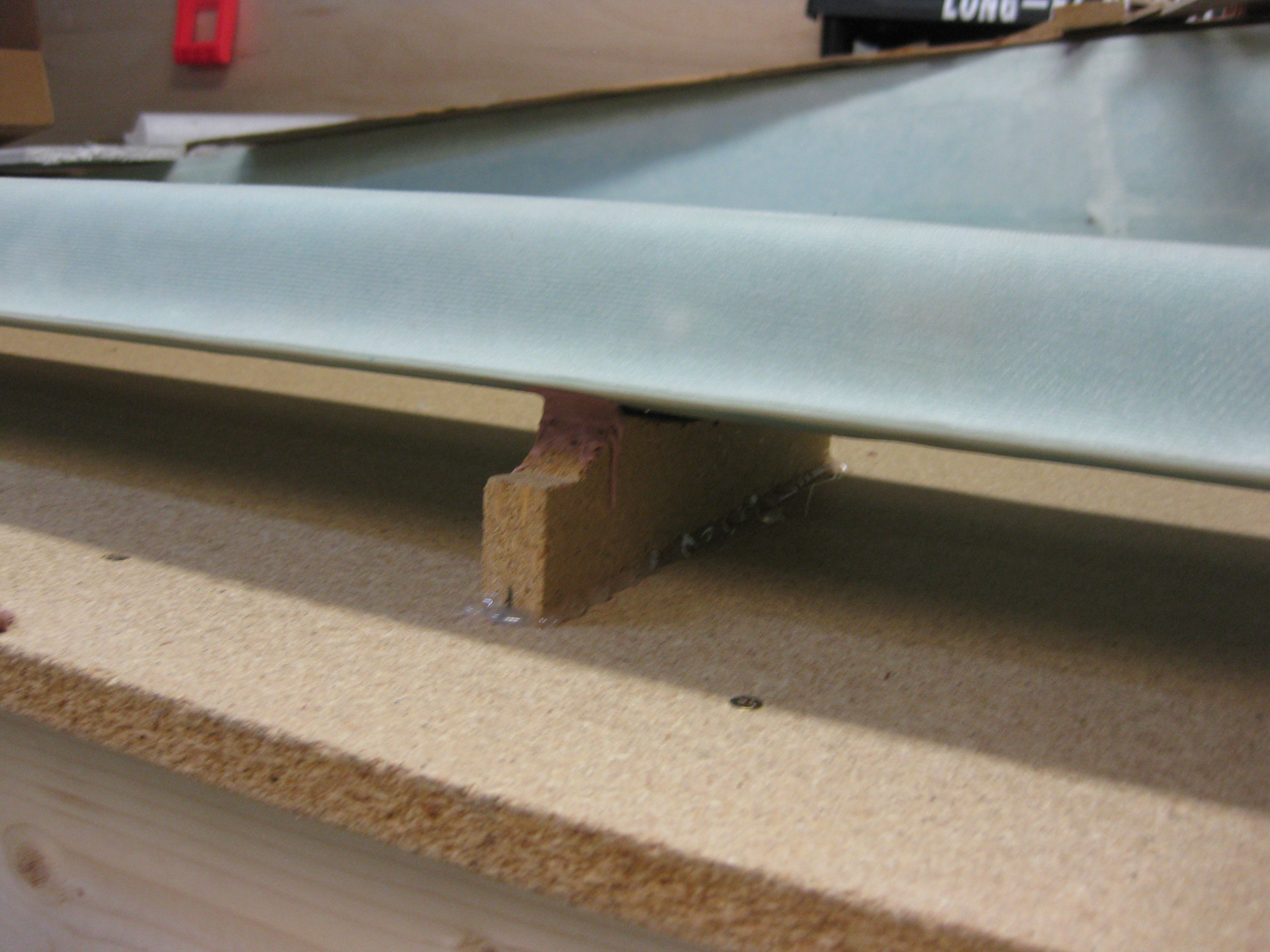
After Sohail left, I worked on getting the canard mounted upside down on the workbench. Thus, my first order of business was to secure the “K” mounts to the workbench surface.

I had thought about either hard-mounting the “K” mounts with screws & maybe some brackets, but I really wanted to minimize the holes in the workbench top. Plus, all but one of the “K” mounts are made of particle board and I didn’t want to add any stress to them by drilling holes, etc.
Another option was of course bondo, but I didn’t want the mess, the smell or the pain of sanding it off the workbench surface after removing the “K” mounts. As you can see by the pics, I went the hot glue route. Hot glue has plenty of strength for the job and it cleans up fairly easily.
After ensuring the “K” mounts were aligned & spaced properly, I hot glued them to the workbench top.

•••
4 October 2015 — Today I undertook my first official act of finishing a surface on this Long-EZ. As I mentioned before, I re-read the notes & material I had on finishing to brush up on this endeavor that apparently seems to be half science and half art.
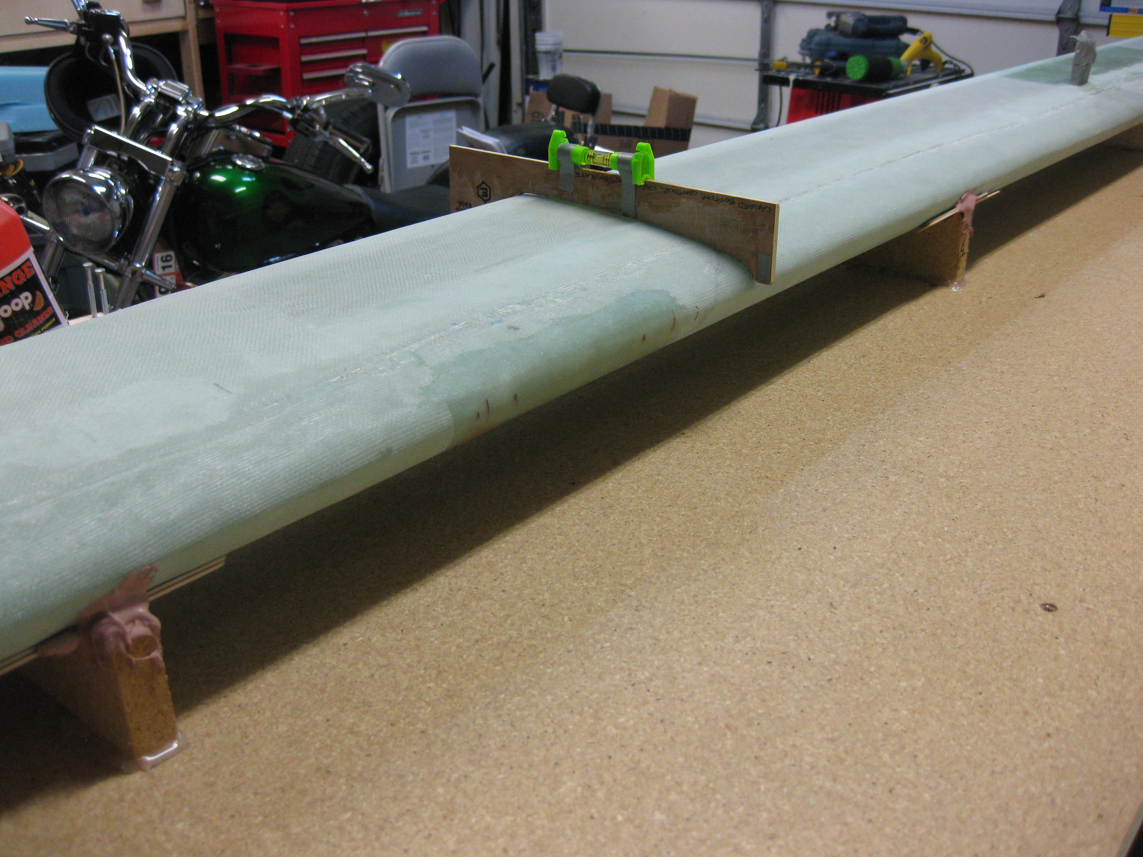
I started out the morning by confirming the side-to-side slant of my workbench so I would know how to position the canard to match the workbench surface. My first thought was to simply use cargo straps in the center area of the canard, but after playing around with the whole setup I realized that the “K” mounts weren’t entirely even (how I had placed them, and they were now glued to the table… I believe this is in concert with slight differences with the top surface of the canard as well). This meant that the contacts between the underside (actually the top) of the canard as it lay here was not in perfect contact with the “K” mounts. When I tightened the tie-down straps on each side of the mounting tabs, I was getting all kinds of weird angles due to the force down on the center of the canard, making the outboard areas seat differently on the “K” mounts.
After playing around with the straps for about 30 minutes, I realized that I had to call “no joy” on this method and resort to something I really didn’t want to use: Bondo.
I spent about another 45 minutes working to get the canard to lie naturally on the supports without any stress from the top (technically bottom canard surface) of the canard in this position. Since the spar cap may be higher on the aft side in one area of the canard and then higher on the forward side 2 feet down the canard, there are a myriad of tiny surface variances that affect how the level attached to the “E” template will read. I spent a lot of time figuring out where my “normal” areas were that I was getting good readings, then I found the locations that had weird readings for any surface anomalies rearing their ugly head.
Again, I started with my digital level crossways on the table, as well testing my little bubble level that I taped to the top of the “E” template.
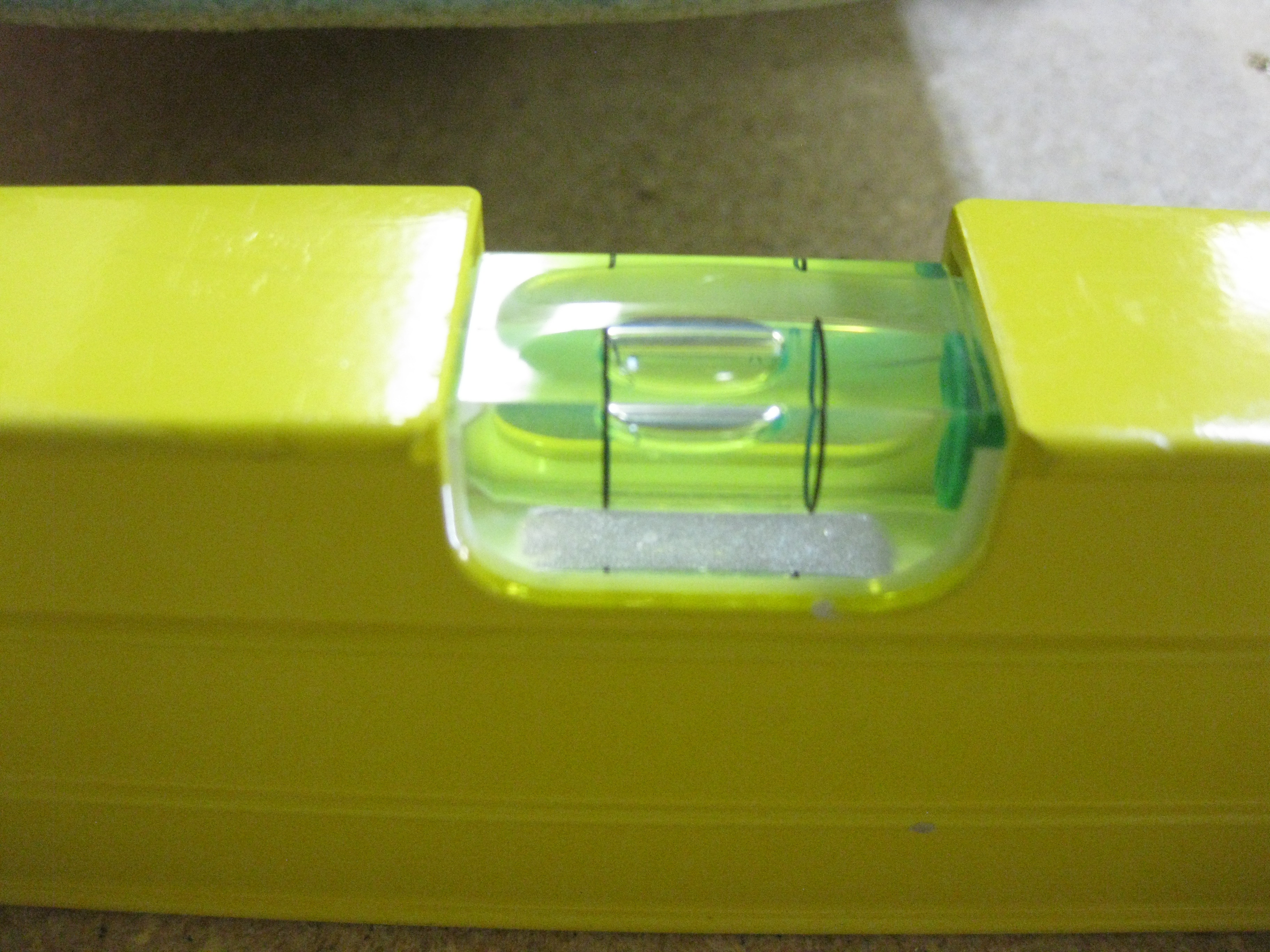
Below is the “E” template at the far Right side of the canard, the middle of the canard, and on the Left side of the canard (of course all underside), respectively. As you can see, the bubble is situated in pretty much the same spot on all of them.

Happy with the position of the canard, I went about the nasty task of Bondo’ing the canard to the “K” mounts.
After I was finished with the Bondo and as it cured, I took my Bottom-side Canard Contour Sanding Block outside and shot it with 3M Super 77 spray glue, along with the actual backing of the sticky sandpaper. Since it takes a bit of time for the spray glue to set up, I went ahead and weighed the sandpaper down to get it to lay correctly in the contoured area.
After messing around with getting the sandpaper weighed down, I went back to the canard and spent about 5 minutes double checking that its angle & elevation were correct in relation to the workbench. Thankfully, it was.
And below are some shots of the Bondo holding the canard in its correct position.
With the canard nice, snug & secure, I took one last opportunity to sand the LE overlap glass seam and any other overly bright & shiny spots. After my sanding spree, I vacuumed up the mess and then cleaned the canard surface with an incredible effective cleaning solution: water!
•••
To streamline this site, I’ve removed the pages on the finishing of the canard since they’re also posted in Chapter 25. To see the Finishing of the Roncz Canard, please visit Chapter 25 – Finishing Canard.
•••
8 October 2015 — Last night I had a fairly lengthy discussion with my buddy Mike Beasley on the finer points of finishing the composite surfaces on Long-EZs. In fact, at Christmas-time last year, Joe Caraggio went down to Georgia (does that make Joe the devi . . . hmmmm? Interesting, but I digress) to assist in Mike in finishing his bird. So, during my discussion with Mike I got both his take and a lot of what he picked up from Joe on finishing techniques.
In addition, after having met the venerable Terry Schubert (Editor of Central States Association newsletter) at Rough River, I’ve been leaning on his guru-ship as well to ensure I don’t muck anything up! Terry has been very generous in offering me advice & info that has greatly facilitated my build progress.
Let me reiterate: this is the first round of finishing that I’ve done (ever!) and obviously the finish is the one HUGE thing that people see right off the bat when they look at your airplane. It doesn’t matter if the underlying construction of your airplane is strong or weak, or that it’s a thing of beauty or crying out to be covered in gobs of paint to hide its hideousness . . . none of that is truly judged when your bird is sitting on the flight line somewhere. Again, what is judged is how the surface & lines of your airplane flow, and how smooth & glossy the finish is on your paint job.
Thus, I want to get this finishing thing right from jump street.
So let me get off my soapbox and on to the build! Today I started out by taping up the outboard and inboard edges of each side of the canard. The outboard edges need to be epoxy free so that I can of course glass on the Roncz canard swoosh tips after I’m finished installing the elevators. Once the canard swoosh tips get glassed in place, then I’ll finish them as well and blend them into the existing finish on the bottom of the canard, and the top of the canard too for that matter.
The inboard areas will get smoothed out and feathered into the non-finished interior of the canard. This middle area doesn’t get finished to save weight of course since once the canard is mounted it remains buried & hidden inside the confines of the fuselage.
•••
15 October 2015 — Before I went any further with mounting the elevators I gave Mike at Feather Light a call about the Canard TE and the interface gap between the canard and elevators. Since Feather Light cut my canard & elevator cores, I wanted to discuss my slightly high TE as compared to the template in the Roncz canard plans. My TE is just angled slightly less downward as it slopes aft, which makes the ENTIRE TE measure about 0.07″ higher than the diagram in the Roncz canard plans. Since the fishtail on any aerodynamic surface is glassed first, this wouldn’t be an issue of my doing since I merely glassed the bottom of the canard first, which included the already shaped TE fishtail. After a good talk with Mike I felt comfortable in keeping my gap wedges at 0.23″ thick, since this would: A) put the bottom of the elevators ever so slightly toward their original position as per plans, and more importantly B) still give me an appropriate gap, especially once the finish and paint is complete. So, I pulled the trigger & moved on!
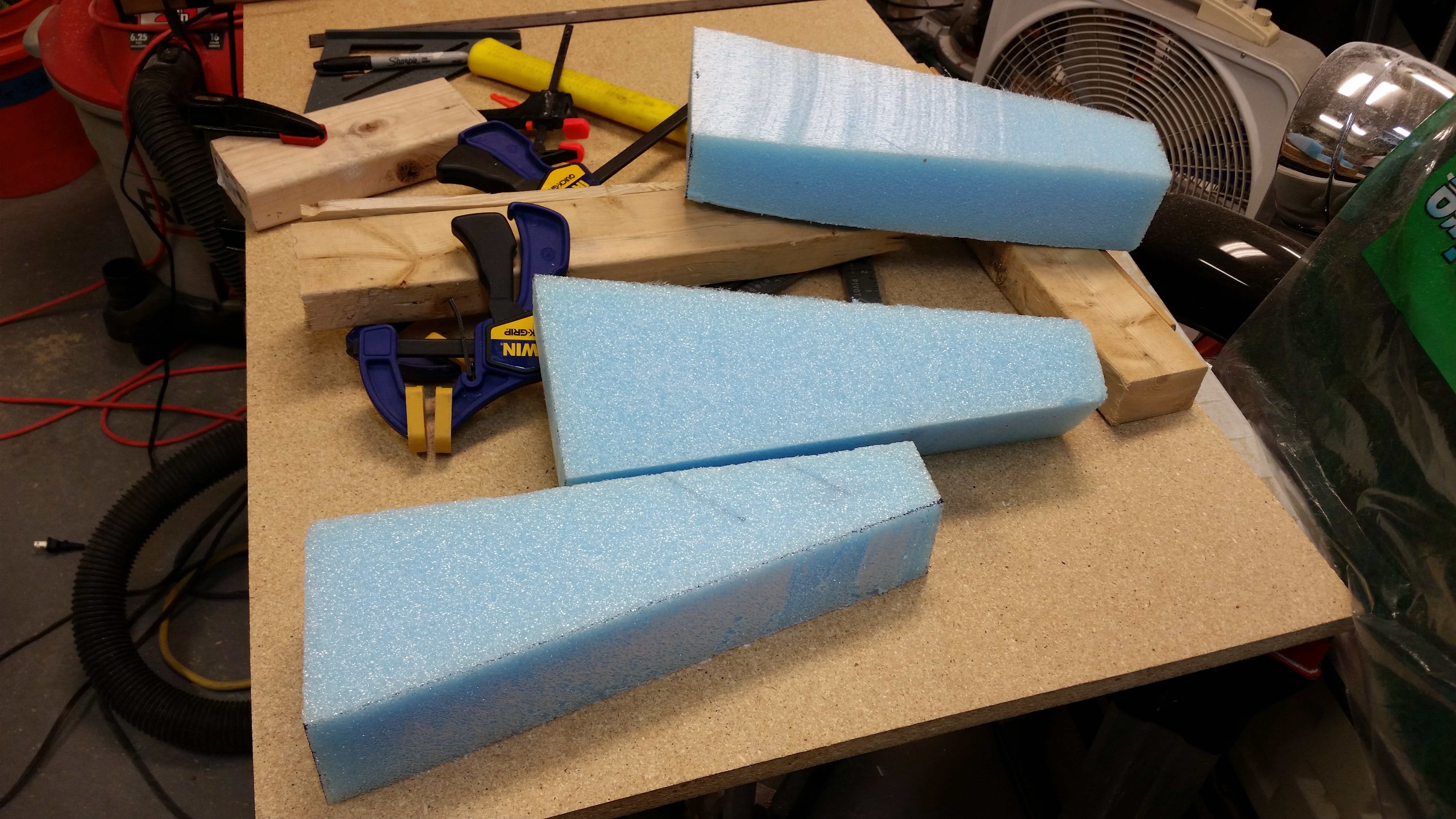
While the elevator hinges’ flox cures I attempted to be productive by cutting the blue foam wedges for the Roncz canard swoosh tips. I figured the easiest, cleanest way to cut the blue foam was using the hot wire cutter.
I added a 1/4″ scrap runner to the top of two 17″ long 2×3’s that I cut. Of course the 2×3’s are, interestingly enough, 2-1/2″ wide. I then clamped the 2×3’s on each side of the first piece of blue foam and tested it out.
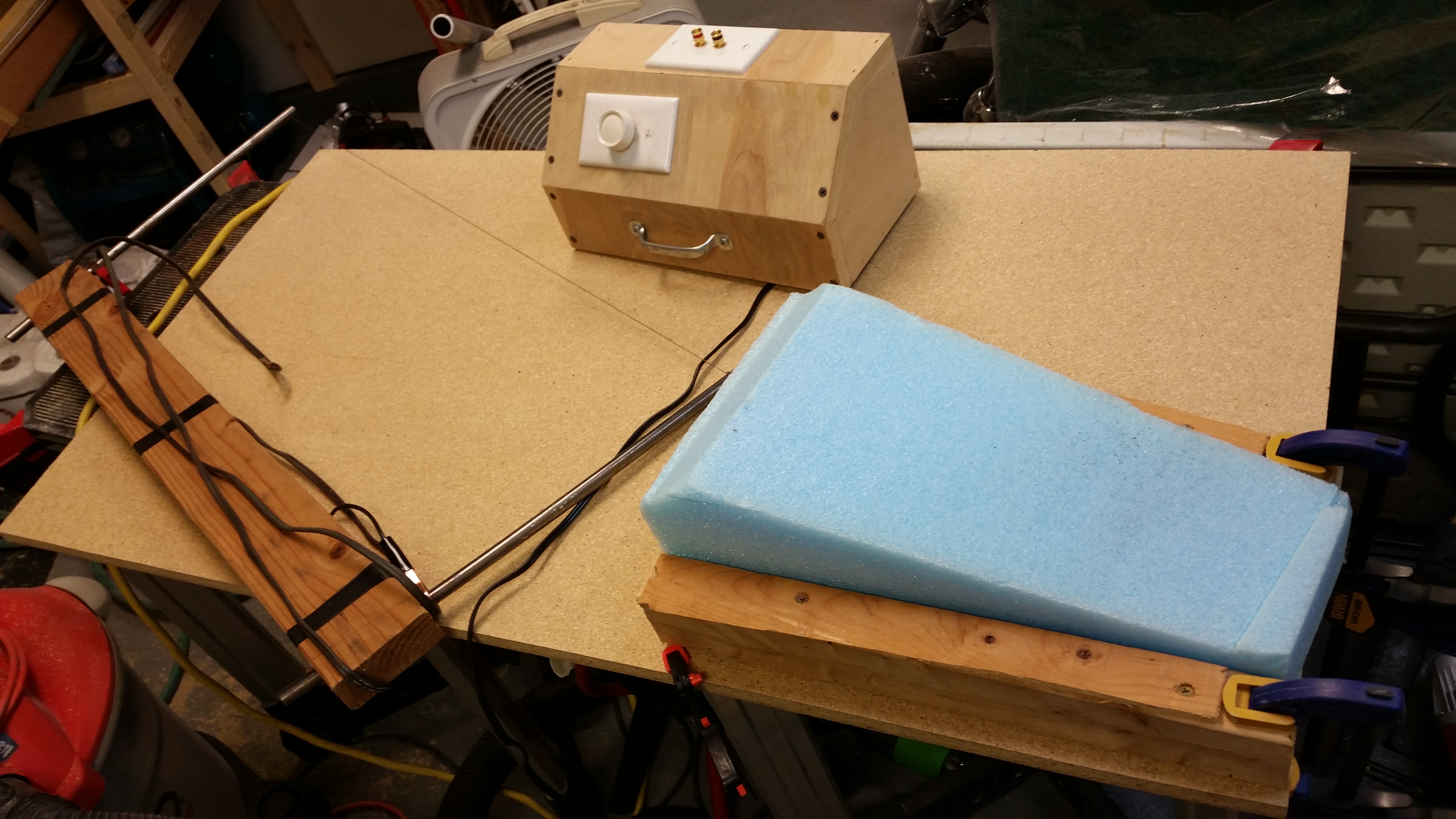
And here’s the result. Not bad, but the hot wire cutter definitely felt “dull.”
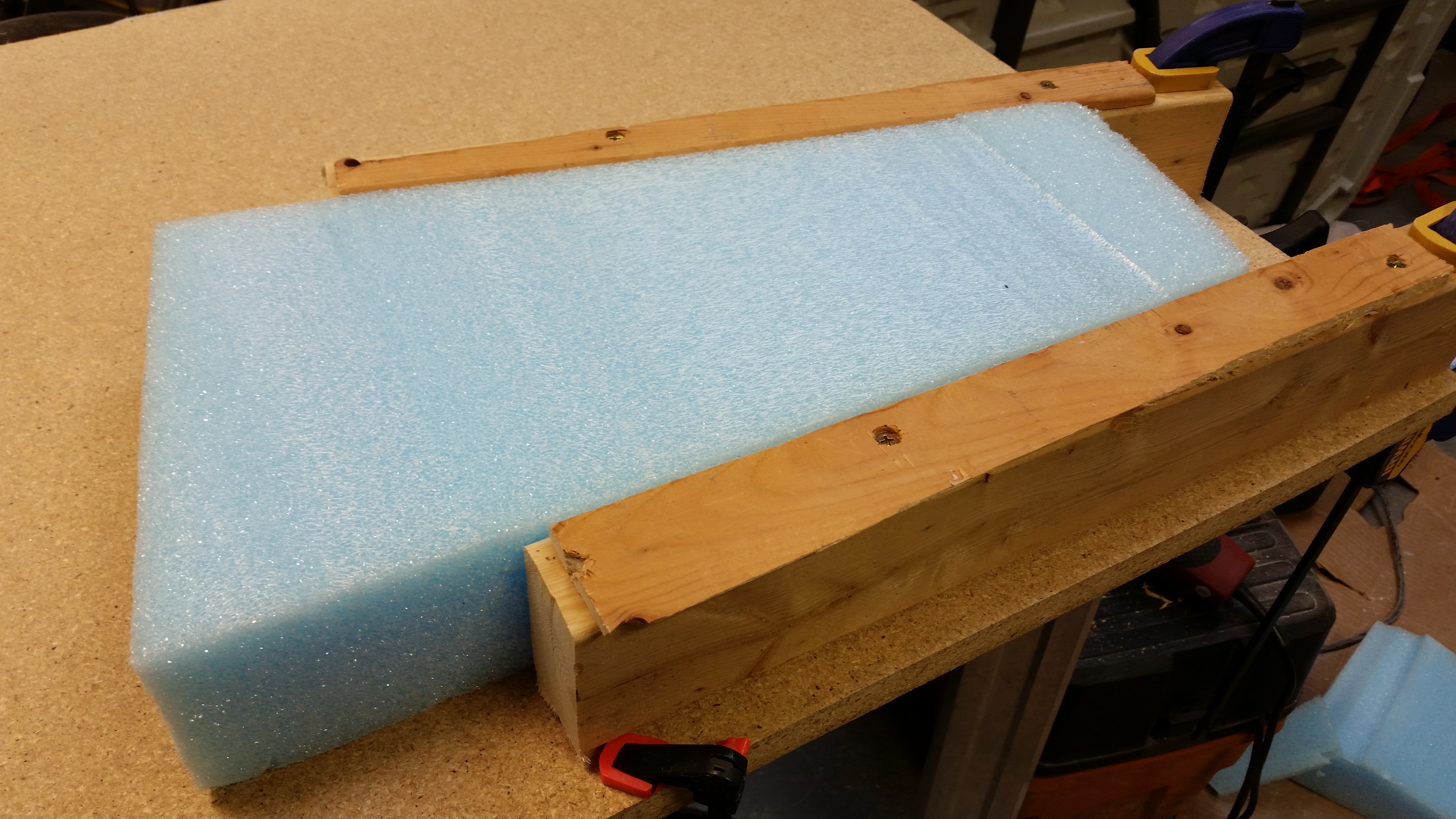
I continued cutting the first blue foam piece to get the swoosh tip piece as per the plans dimensions.
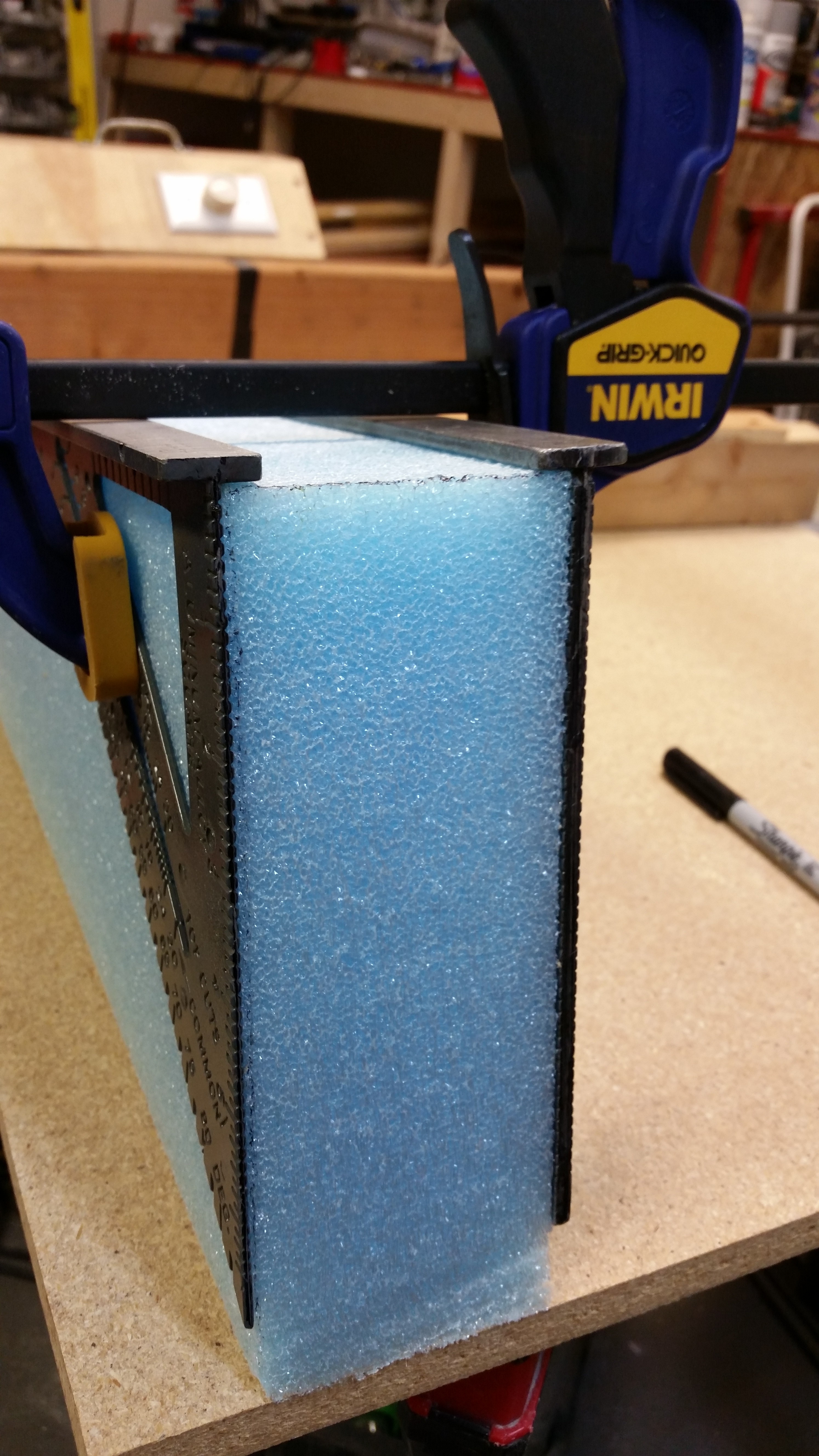

And then I grabbed another piece of foam to make the second blue foam canard swoosh tip wedge piece.
Funny, but if I had started with the first piece of foam, I would have ended up with the two swoosh tips that I needed. Oh well, now I have a spare!
Since I won’t mess with the elevators or canard for a full 24 hours after I set the hinges, I’ll be working on getting the top canard contour “E” template traced and made into a canard top contour sanding block just as I did for the bottom. I’ll also find the pieces of UNI for the canard tips, locate and/or procure the plastic tubing for the canard tip elevator hinge pin bracket, etc.
•••
16 October 2015 — I traced out the Top Canard Contour Template “E” onto one of the 2×3’s I used for cutting the blue foam swoosh tips and made the first half of the top canard contour sanding block.
Also, when I was at Home Depot yesterday I looked at buying a 24″ long piece of 4″ PVC pipe to sand the swoosh tip foam. They wanted $8 for it and I wasn’t in the mood to spend that much on a one time use thing, so I simply recycled my 2″ OD PVC pipe that I used to Alodine the Spool Tube. I attached a piece of 36 grit PSA sandpaper to it and plastic wrapped to allow the paper to fully stick to the PVC tube.
I then ripped the other 2×3 to 1.1″ wide, attached the two halves, gave the interior working edge a good sanding to get the surface evenly matched, drilled the lag screw pilot holes and then mounted the lag screw support legs. As you can see below, the canard top contour sanding block is complete.
I did tweak the TE of the top canard sanding block just a hair so that my sanding of the canard top wouldn’t end up being a “let’s destroy the TE” party. Last week I traced out the actual-sized profile of the canard from the Roncz plans to double check my progress. And as per my discussion with Mike at Feather Light, you may be able to make out that my TE on the canard is definitely just a tad higher than the Roncz plans outline.
•••
17 October 2015 — After I confirmed that the elevators good, I started the process of attaching the blue foam canard tips. Now, when I hot wired the foam tips one came out a little narrow than the other. With my canard TE just a bit straighter (read: higher), it messed with the 1″ dimension that gets measured up from the TE to the upper side of the foam. On the narrower blue foam wedge I couldn’t squeak out this 1″, so I ended up grabbing a wood handsaw and cutting another blue foam canard end piece.
I then temporarily attached a blue foam swoosh tip blank on the left side of the canard with the elevator hinge pin sticking out a couple of inches. I noted that I had over 1″ to work with above the canard TE and ensured that my spacing was good.
One thing that you may notice that is not per plans is that I started my canard swoosh tip attachment endeavor with the canard mounted upside down. Per plans this step starts by flipping the canard right side up, but since my canard is “bolted” to the table via Bondo, I decided to start with it upside down and then flip after I had micro’d the tips on. This would allow me to see both sides of the micro bond and ensure all is good.
Here’s the right side of the canard where I repeated the same process as the left.

I then confirmed that the dimensions of the blue foam tips would work by marking it up as per plans, only in the upside down configuration. I also outlined the end profile of the canard to know where to micro the blue foam tip when attaching it to the canard end.

Below are a couple wide angle shots of the canard with the blue foam tips attached. The first one is the with the canard upside down, and the second pic shows the canard right side up. I guess you could say the main reason I attached the foam tips to the canard while it was upside down is time. I wanted to the tips mounted and the micro curing before taking the time to carefully detach the canard from its perch… which I obviously did after the tips were micro’d on.

A long view . . .
Here’s a more close up shot of the tip micro’d in place while the canard was still upside down.
After the micro cured I removed the tape securing the blocks.
I then rounded the front of each blue foam tip in line with my initial plan for the shape of the swoosh tip.
Tomorrow I plan to get the canard swoosh tips shaped and glassed, at least the top sides.
•••
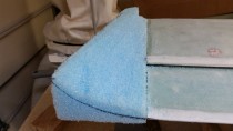
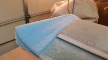
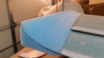
18 October 2015 — I started out early this morning carving the “swoosh” tips out of the blue foam that I micro’d to the canard last night. This is one of those very distinctive exciting steps in building a canard aircraft since, obviously, these swoosh tips make a stylistic statement about the bird. Also, since Roncz canards are all built with the same plans there’s not that big of a difference in the “I’m cool” department . . . the scenario is more along the lines of, “Hey, check out all these nice turned up tipped Roncz canards here, and mine look like crap!” Ha! That’s what I’m trying to avoid!
Thus, I did exactly what the plans stated and started out slowly. BTW, I grouped all the pics in a series per the angle of the camera shot so you can see a progression of the foam taking shape.
I think the biggest Aha! moment was realizing that the toughest part of this whole carving exercise is the first 3-4″ on the LE side. Wow! What a head-scratcher as far as, “What the heck do I do here? And what do I really what this thing to look like?” I went back upstairs at this point (after having carved away on the front side) to look at the large pics in the Roncz plans and check out a half dozen websites where I knew I could find some pics of Roncz canard tips. Talk about one area that I never gave much thought to, even as I started carving! Another crazy thing is that you really don’t know exactly how good the top swoosh tip contour is going to look until after the bottom is finished.
Oh, well. After getting a better mental picture I went back to carving. I will say that if I had known what I know now, I would have had a better plan for that front area. I’m happy with how it turned out, but I would have gone in just a slightly different direction if I hadn’t starting carving without an idea of what the front LE area transition should look like.
After doing my best to make sure that I had a smooth surface with good transitions, I pulled the trigger and glassed the top skin of the right swoosh tip with 2-plies of UNI biased in the typical 30° to each other.
Some rear views . . .

And some top views . . .
A number of hours later after I knife-trimmed it with the Fein saw, and then sanded the edges.
To show you my original thinking, take a look at the template to the right in the pic below. That’s how I had originally envisioned the nose of the swoosh tip. That quickly transitioned into an insane template that would have been better described using a NASA 3D modeling program. I thought maybe a working knowledge of geometry may come in handy here . . . oh, no, folks! We’re talking calculus & quantum physics for this project!
Why?! Well, in Burt’s sadistic command, “form to a pleasing shape” I can see where it may not be a big deal. Except in this case you have to make a mirror of that which you just free formed into a “pleasing shape!”
So here’s round two of “forming into a pleasing shape.” Obviously side 2 is all about replicating side 1 . . . some heavy stuff here my friends!
I started in quickly and got the left side canard tip to pic #1 in about 5 minutes, and to pic #4 in about 20 minutes. But after I got the basic shape, I then kept going back and forth from one side of the canard to other. Measuring distance, elevation, slope, etc. to get this side as close to the other side as possible. I guess the saving grace is that these sit about 11 feet apart from each other on opposite ends of the canard, so it obscures any slight differences.
Nonetheless, at the end of another 20 minutes or so, I felt like I had a good mirror replica of the right side swoosh tip.
I prepped the left side canard swoosh tip for glassing. One thing of note is that the back to top corner was a little dinged up, so I added a small buttress to keep the aft skin layup straight.

I then laid up the top of the left side canard swoosh tip with 2-plies of UNI just like the right side. I will say that after I was finished I had an issue with the shape of the left canard tip. You see, after I put the wood support piece in place I needed to finish sanding the outboard top edge to a fine point to get the shape to match the other side (this was before the layup). Well, I used my Perma-Grit half moon sanding toold which–unbeknownst to me at the time– caused a much sharper radius in the foam right at where it made it’s final turn up at the edge. It’s basically like comparing the curve of a “C” like I had on the right side compared to the shape of a “U” which I had now on the left side. Again, this was all occurring in the very outboard upturn, and all within about 3/4″ of an inch from the edge.
After I glassed it, I compare it to the right side and that outboard upturn was staring me in the face. Since I hadn’t feathered that final removal of foam for the sharp edged upturn, it was showing up much more prominently after glassing. To be clear, if this was the way both sides looked, it would be fine and not something that looks like a mistake. It was simply a different style, or look, than what I had on the right side.
After a couple more double takes, and comparing it to the other side again, I couldn’t take it. I peeled back the UNI, grabbed the 2″ diameter PVC tube sander (that I had made for shaping the swoosh tips) and simply feathered the micro-covered foam down to “a pleasing shape!” I then made sure it was what I wanted and matched the other side, and simply laid the UNI back into place and squeegeed it flat. It all took maybe 5 minutes and I was then infinitely happier with the outcome of the left side swoosh tip layup since it flowed with a nice gradual curve from base to tip just like the right side.
Since I had a little bit of pure epoxy left over, I grabbed the BID scrap box and a piece of plastic to make a 4-ply BID sheet, of which to cut out a Vortilon or two. I laid the 4 plies of BID into a pre-preg setup and poured all the epoxy into the layup. After heating up the pre-preg with the heat gun it flowed well enough to wet out all the epoxy. I then put another plate on top of it and weighed it down with my heavy tool bag (right pic).
Here’s a few shots of the finished top side of the right swoosh tip.
Next will be the shaping and glassing of the bottom sides of the canard swoosh tips. Then back to working on the elevators to get the weights mounted, etc.
•••
19 October 2015 — I started out today sanding the right side canard swoosh tip to shape. Besides ensuring that you have a minimum of 0.4″ of glass to glass contact, the Roncz canard plans doesn’t really go into detail on glassing the bottom glass to the top. So besides the glass to glass contact, I made a little trough all along where the two glass edges meet. On the foam inside edge I ran a narrow bead of flox all along the edge to give it some strength before glassing it.
The actually sanding and shaping went a heck of lot quicker than the topside since there’s only so much you can do with the bottom side. I tried out some 1/4″ OD Nylaflow and the 3/16″ ID seamed to work perfectly for the hinge pin conduit through the swoosh tip, so I cut a small piece, filled it with twisted Saran (plastic) wrap to keep the gunk out, and installed into the hole made by the original hinge pin.
The picture on the left shows the initial glassed swoosh tip, and the next two are a few hours later after I added dry micro to the edge after knife trimming the glass in its “green” stage (still tacky but definitely well on its way to curing).
In the evening after it had cured, I marked the hinge pin conduit and cut it out.
I drilled out the saran wrap and cleaned out the conduit with a 3/16″ drill bit. I used a laser to make sure the conduit was clear.
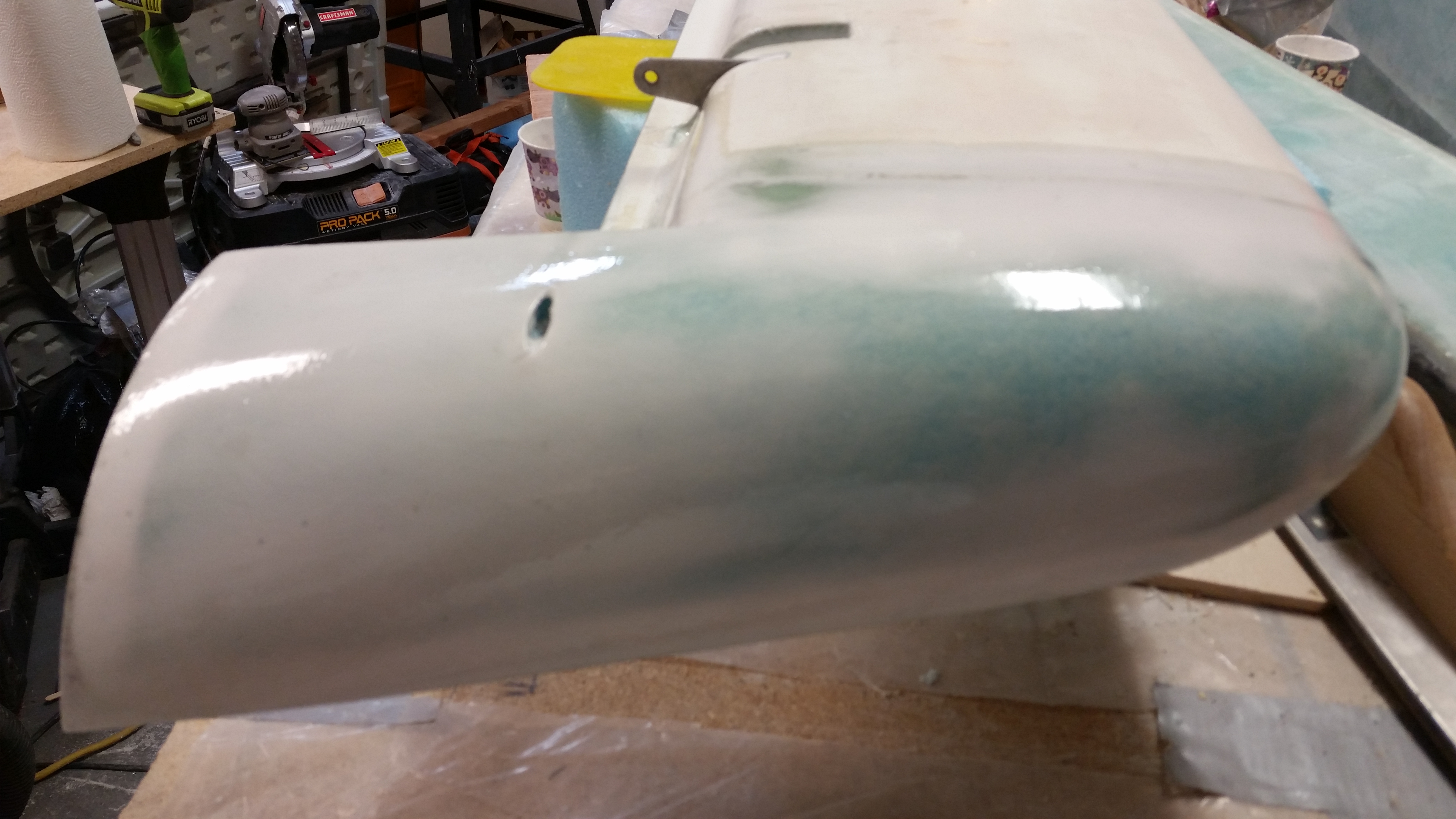
Below are some random pics I took of the right-side canard swoosh tip with the canard in the normal upright position.
Here’s some better pics of they Nylaflow that I used for the hinge pin conduit. This was right before I inserted it into the foam as I was glassing the lower left side canard swoosh tip.

Since I had the hinge pins out for glassing the lower swoosh tips, I grabbed one to work on the outboard end of it. I shaped it with the Dremel tool, then I drilled a 1/16″ hole in it to allow for its removal later on with something like a scribe.
And here’s the lower left canard swoosh tip after I razor trimmed it and added dry micro.
Since I had used some leftover epoxy yesterday to make a set of Vortilons, today I wrote it into the work plan to finish the set for both wings. Here’s they 4-ply BID layup for two more sets of Vortilons.
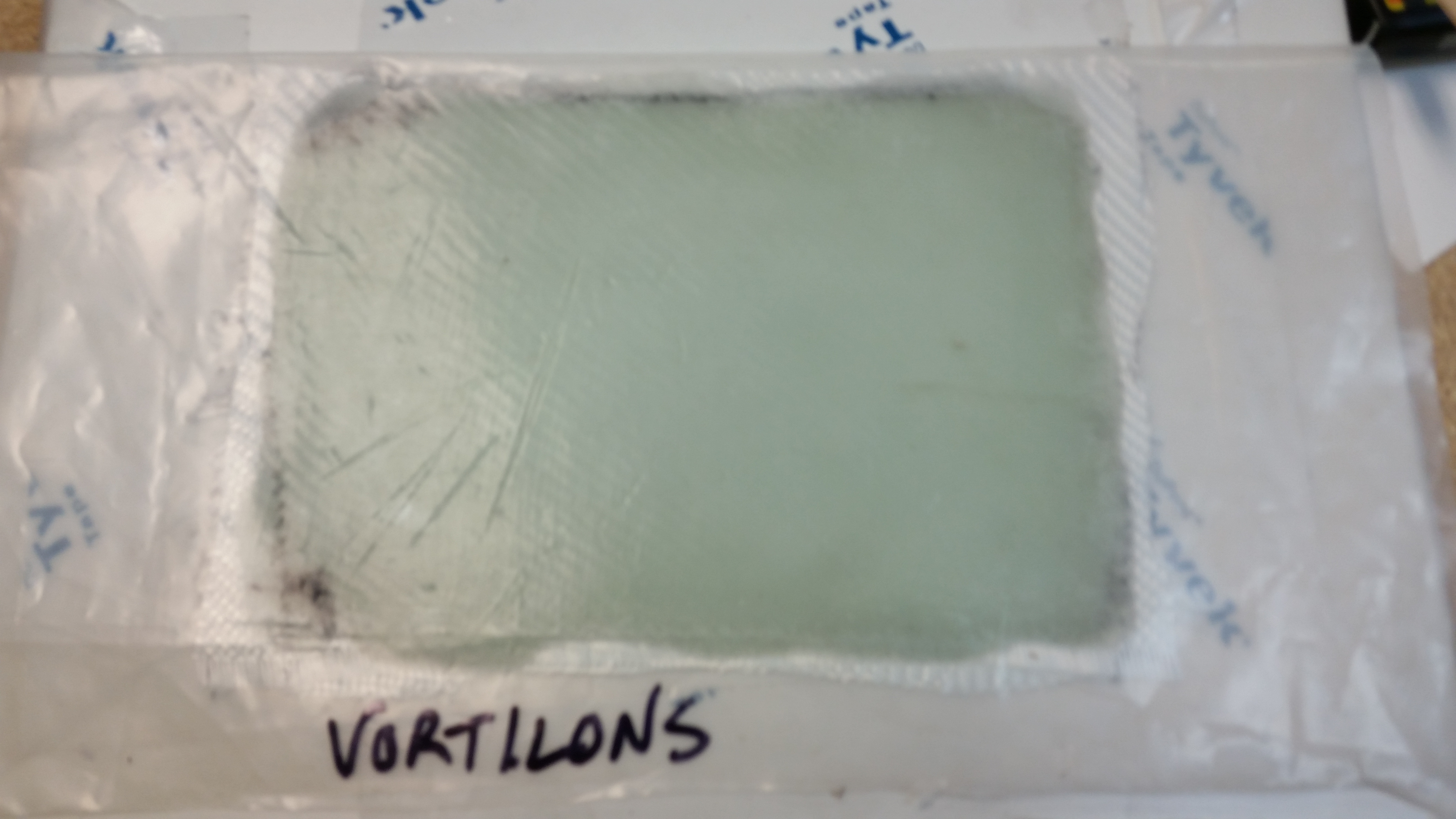
And here are the initial two that I cut from the glass I laid up yesterday. These are the largest of the 3 sets of Vortilons.
Finally, here’s the hinge pin hole from the left side swoosh tip. Since the glass was still in the green stage, I took the opportunity to razor cut the whole for the hinge pin conduit. You can still see the quite tacky micro in the right photo.

Next I’ll continue working on the swoosh tips and the elevators to get the entire canard & elevator combo completed. There are no major tasks left after the swoosh tips were glassed, but there sure are a myriad of small tasks that need to be accomplished before I can call these officially done.
•••
20 October 2015 — I started off by knocking out the small 1-ply BID layup that sits just inside the swoosh tip on each end of the canard. The Roncz canard plans states to create a flox corner around the perimeter of the foam and then layup the glass.
Personally, I would have preferred to have this “mini root rib” set back a little bit somewhat like the front inboard rib of the wing, with a little bit of an edge with the vertical wall of this layup sunk back from the edge, say a 1/2″ or so. The problem is that this adds a little more time to the layup, and since I’m not sure if I would be adding to some kind of drag here or something else negative, I simply pressed forward with the plans version of this layup.
I cut a little trough around the hinge pin tube since there wasn’t a lot of meat or mass holding them into place on either side. Also, once I put the flox in the corners, there was about 1.5 square inches of foam left so I simply finished out the tiny bit of flox I had left by using it to surface prep the foam vs. spending the time to mix up micro. I KNOW! The weight I added by such reckless building should be noted! (Read: sarcasm!)
While the elevator weight flox was curing, I traced the remaining Vortilons onto the 4-BID sheet I had just laid up. I then used a jig saw to cut them out (last time I did it by hand with a coping saw). When I traced them I used a Sharpie to make thick lines, so they’re cut just a hair oversized. I’ll dial in the exact shape when I go to install them.

Here’s a shot of inboard swoosh tip layup after I knife trimmed it. The other side looks pretty much the same.
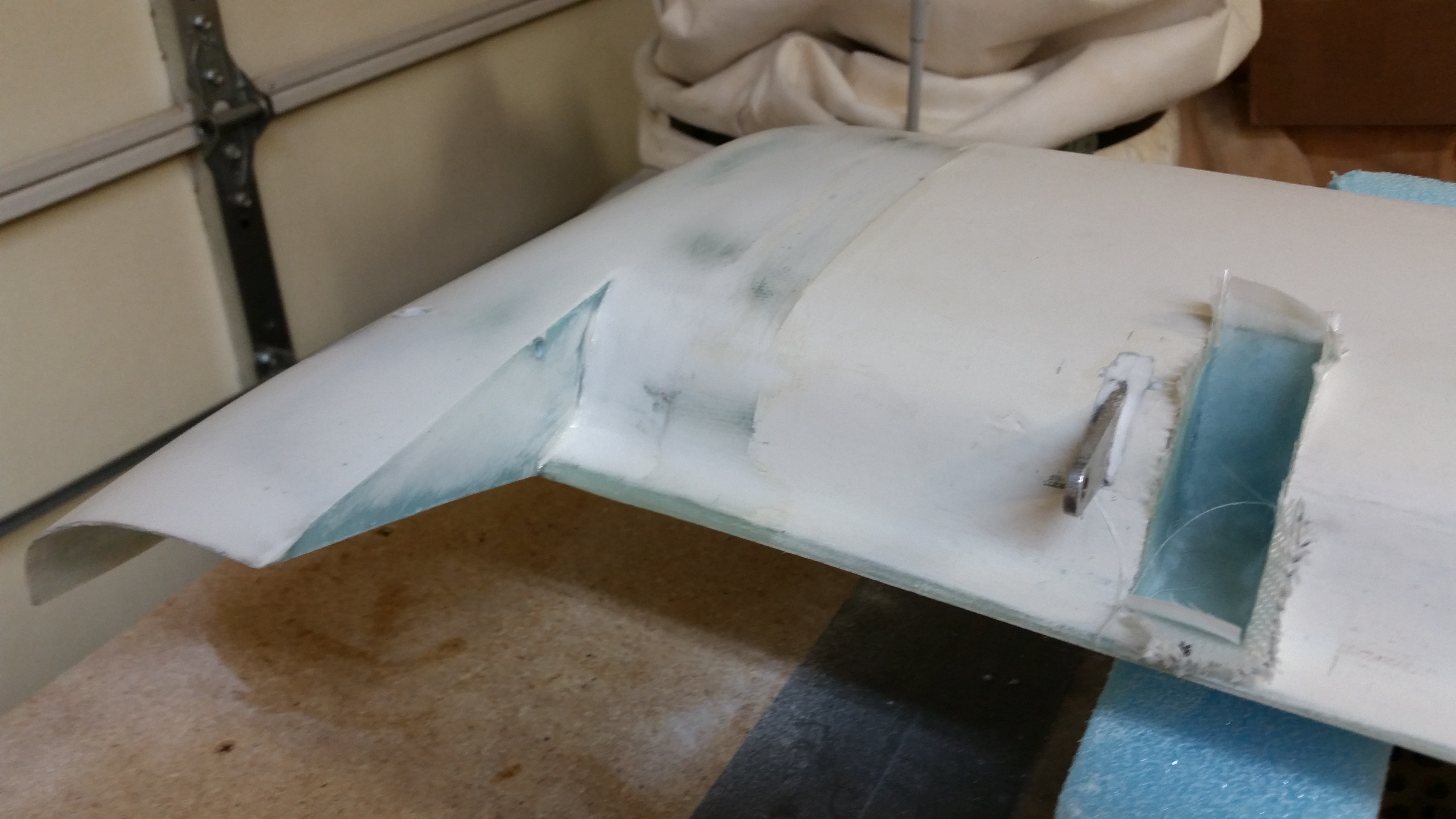
As I was working on other stuff, I noted that this was the first time I had seen the canard in this state: elevators removed and the hinge tabs showing. Something different so I snapped a pic.
The plan is to simply finish all the number of little jobs that will get Chapters 10 & 11 into the history books. I’ll finish adding the elevator weights and cut the slots into the canard for the outboard elevator weights, glass those slots, etc.
•••
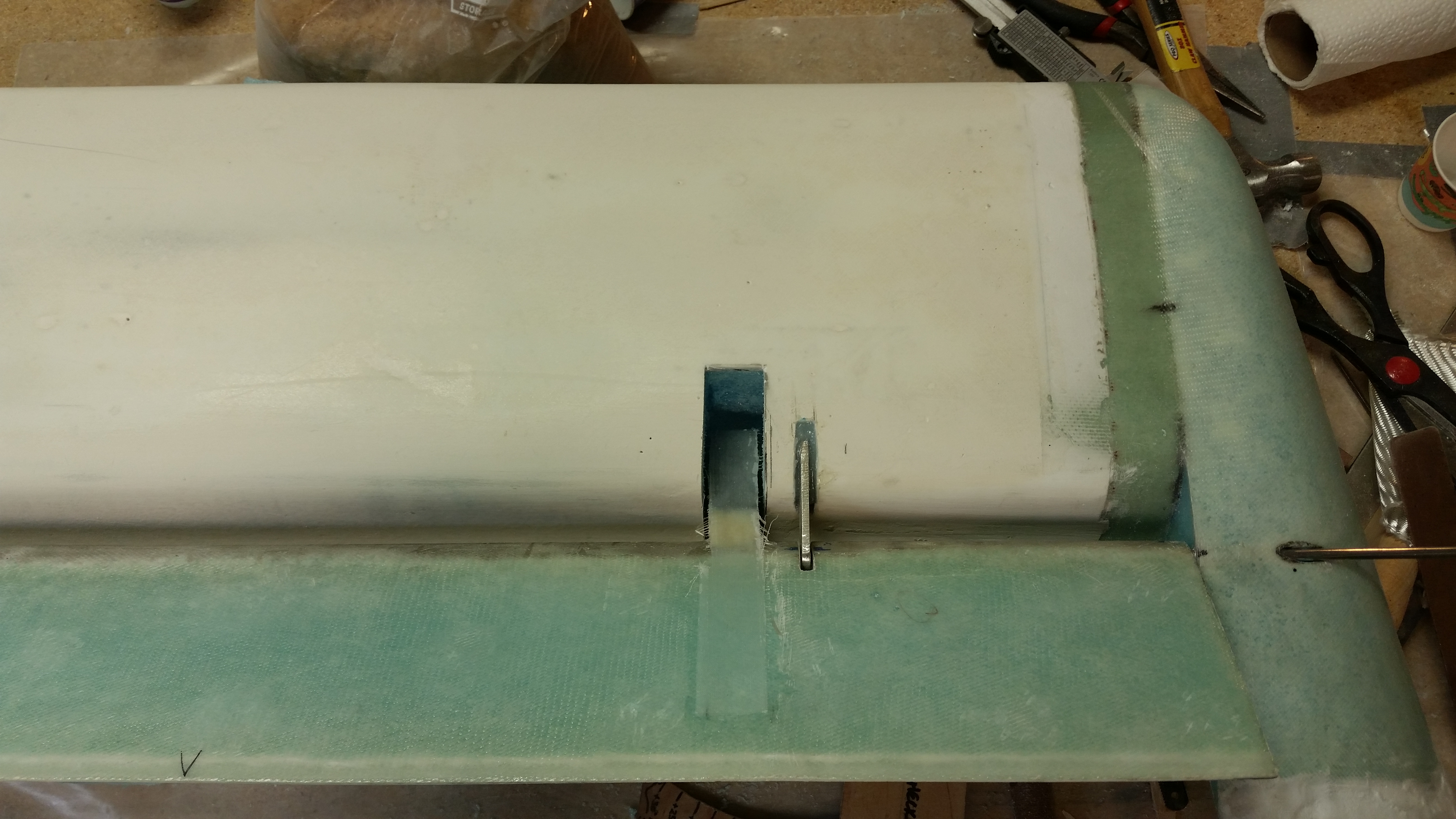
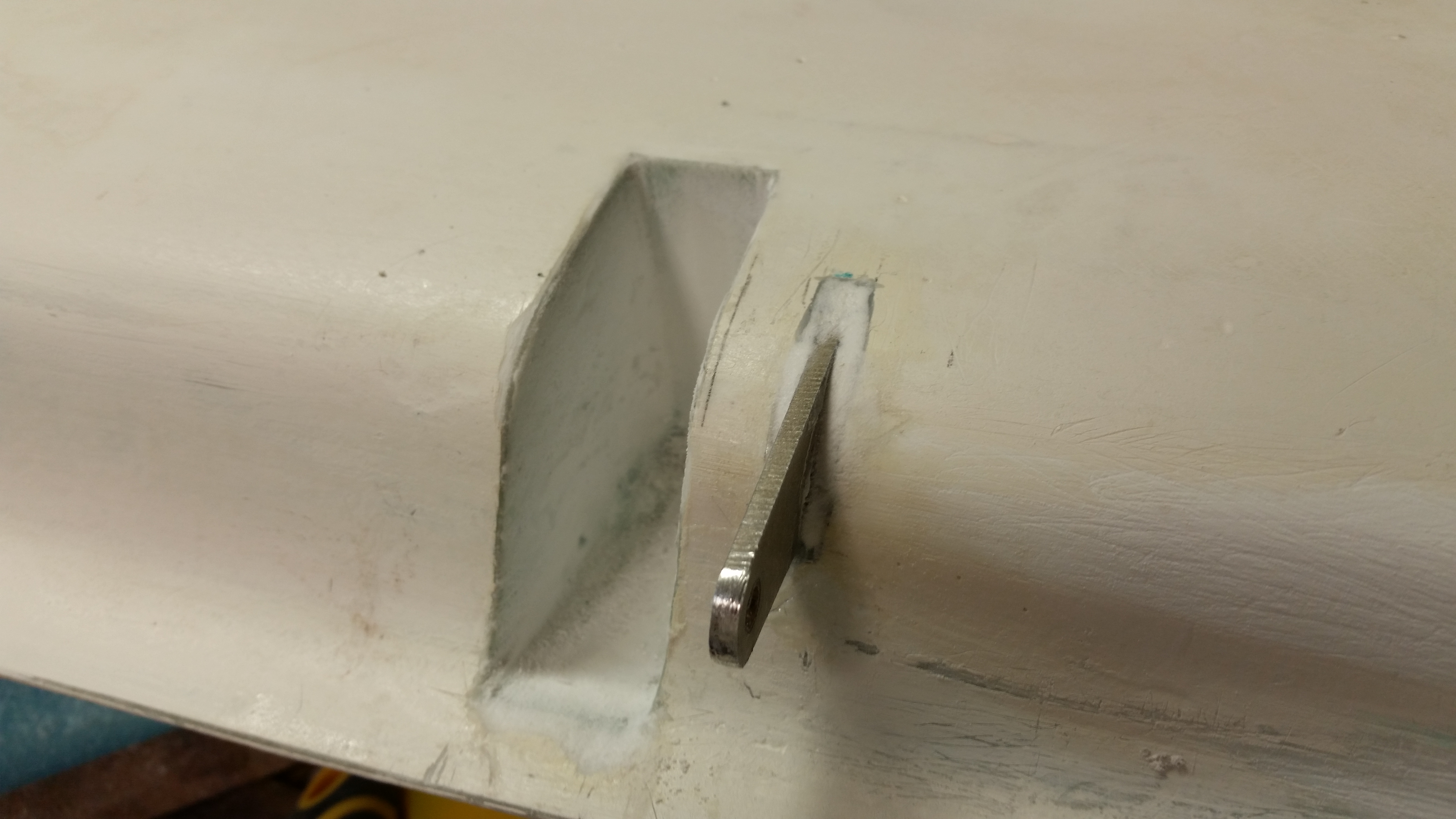
21 October 2015 — I mocked up the elevators and made the embedded notch in the canard on the left side to allow clearance for the outboard elevator weight.

Here’s the left elevator with attached outboard weight moving freely in/out of the notch on the canard.
•••
22 October 2015 — With the elevator balancing drama unfolding, I didn’t cut the outboard elevator weight notch in the canard on the right side. But I laid up the 1-ply BID in the left side elevator weight “pocket.”
Since I had extra epoxy left over at one point–and hate wasting it–I finished shaping a piece of polyurethane foam into a mold for the elevator weight ice shield. The pics below are immediately after I popped it off the mold and set it on the canard to see how it fit.
Here’s the same ice shield after I trimmed it. I may change the shape later on, but it was a quick kill and for now I know that I have them done and ready for use.

•••
26 October 2015 — Yes, my dear friends, I’m calling the canard complete!
I started off today by cutting out the right elevator weight notch in the canard.
Here I’m checking the opacity of the glass beneath . . . ha!
I measured everything out using the right elevator as a template and then got to work on micro’ing the sides and laying up 1-ply of BID to protect the foam.
BTW, here’s the left side still in the same state I left it in after last night’s cheese grating.
And here are the smaller bits ‘n pieces after I hit them with some 80 grit.
After I got the weight notch sorted out, I mixed up some West epoxy and started applying epoxy swipes to the remaining parts of the bottom of the canard that weren’t finished (swoosh tips, swoosh tip inboard rib, weight notches, etc.).
Here’s a shot of the right inboard swoosh tip area after a couple of coats of epoxy. And a shot of the glassed right elevator notch with 1-ply BID.
Below is a shot about 9 hours after the one above, and the tips are covered with 5 coats of epoxy. I’lll let it cure overnight and sand it tomorrow.
•••
Again, to streamline this site, I’ve removed the pages on the finishing of the canard since they’re also posted in Chapter 25. To see the Finishing of the Roncz Canard, please visit Chapter 25 – Finishing Canard.
•••
26 January 2016 — Today the first thing I did was spend almost a good hour clearing off the canard work bench, and cleaning & organizing the shop.
I then got to work sanding the TE area of the canard with 220 grit sandpaper. I wanted to keep it a finer grit, but after a bit of sanding I realized that 220 just wasn’t getting it all done, so I switched to 150 grit. Much better to get the stubborn areas leveled out & smooth.
I then flipped the canard around & started working on the LE. Although I sanded both the LE & TE, they’re both going to need a decent amount of filler. I want to wait though until I get a (real) high build primer to apply a couple of coats of that before doing any filling with putty, etc.
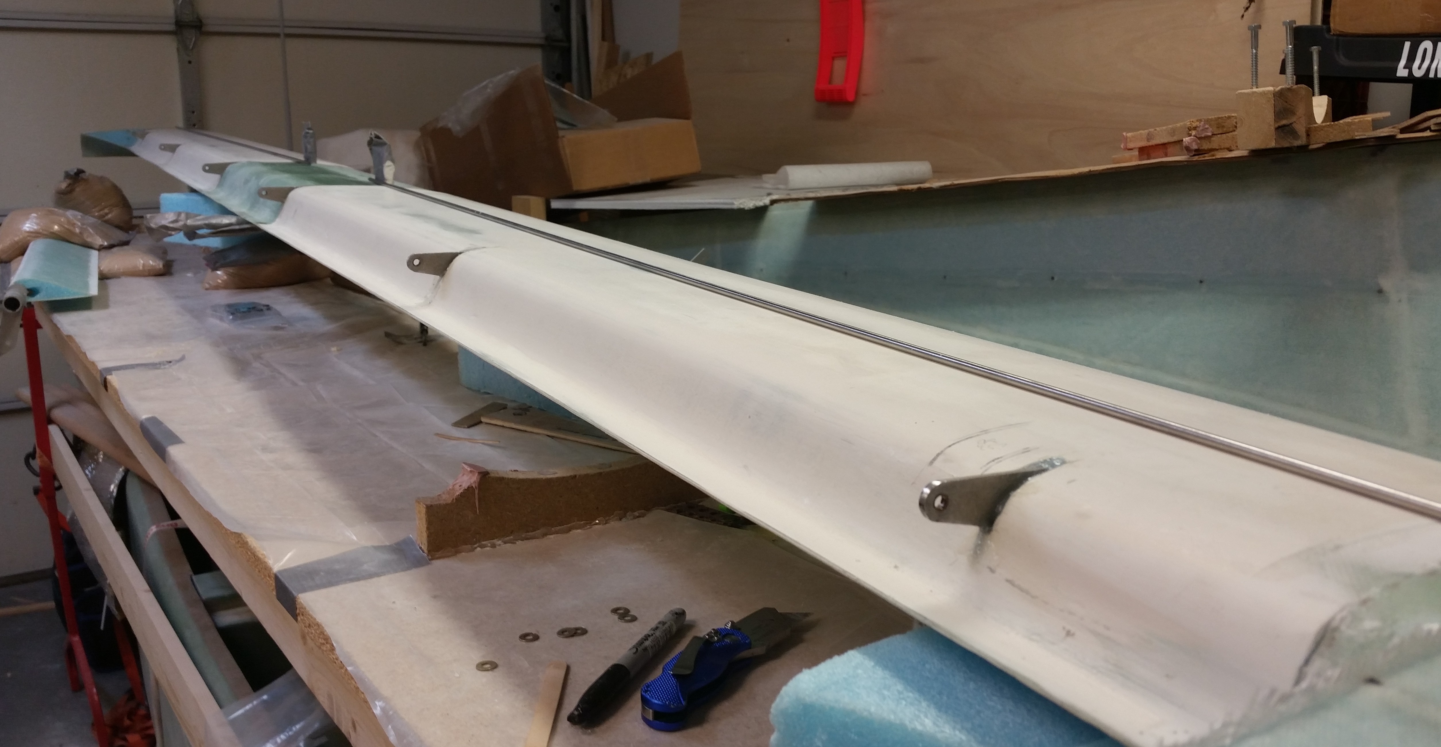
I then reinstalled the hinge pins & remounted the elevators, which resulted in a sheer amount of pain in getting that hinge pin installed [For detailed info on the elevators check out the Chapter 11 page].
Once the elevators were installed, I checked the gap between the bottom of the TE & the top of the elevator. The taped-together popsicle sticks I used to test the spacing were from the original set of spacers I used when I installed the original elevators. I double-checked the width of the spacer and it was right at 0.22″. I checked the fit of the spacer into the gap between the canard TE & the elevator on 3 spots each side: outboard, middle & inboard. Of all 6 spots, I got 3 spacings that were spot on (meaning 0.22″ gap), while the other 3 were just a tad tight (closer to 0.2″). So my spacings are looking great.
All in all, for having to re-glass & remount the elevators, I’m really pleased with the quality & fit of the elevators on the canard.
I then grabbed a couple long shot pics of the canard with the new elevators, both top & bottom views.
•••
26 January 2016 — I started off today by sanding the internal front edge of the outboard elevator weight pocket to allow the clearance required for the weight to move freely within the pocket.
I then taped up each aft outboard elevator corner to protect it from the glazing putty I would apply to the swoosh tips to level up the TE between both sides.
I was planning on waiting until I applied the high build primer to do any surface patching on the canard, but since I was mixing up some glazing putty anyway, I went ahead and applied it to a number of spots on the bottom side of the canard.
I then spent a good 2 hours sanding the bottom of the canard and finished up with the swoosh TE edges to get them to match the TE of the elevators. The putty on the TE is still a bit rough and will need another round of putty & sanding, but I’m waiting until I do the finishing of the elevators to finalize the swoosh tip TE finishing.
You may note in the pic below that I’ll have to add some micro to the right elevator swoosh tip/elevator intersection gap to even it out when I do the final finishing of the elevators & canard.
I decided to hold off on the finishing of the elevators at this time. I do strongly feel that getting the parts finished as they’re completed is a good way to go, but since I’m most likely heading back to school in early February to take the Commercial Rating ground school and flight instruction, I want to focus on getting the main gear and associated components installed as a completed milestone before I start back spending a fair amount of time flying.
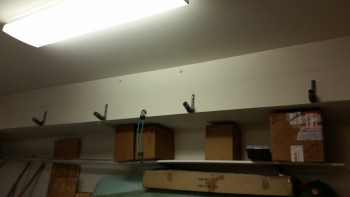
Switching gears: In prep for remounting the canard back onto the wall, I lowered the mounts a few inches to allow for the added swoosh tip ends & elevators that weren’t on the canard when I originally had it mounted up there before.
But before the canard went back up on the wall, I wanted to terminate the canard VOR/LOC & glide slope antenna cables with connectors and check the VSWR.
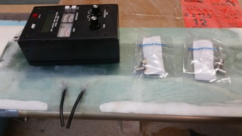
The first step in terminating the antenna connectors was to get down the center conductor of the RG-58 cable by removing 1/8″ off the end of each cable.
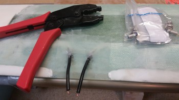
I then crimped on the center coax pins using the RCT-2 crimper (B&C) shown above.
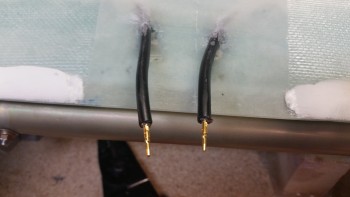
I then slipped on the ferrules.
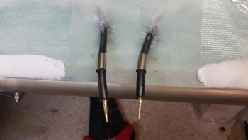
I then stripped away another 1/2″ of the outer jacket using a coax cable stripper. This exposed the cable shield braiding.
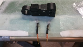
I then slid the main connectors into place, slid the ferrules forward over the braiding and then crimped the connector assemblies into place.
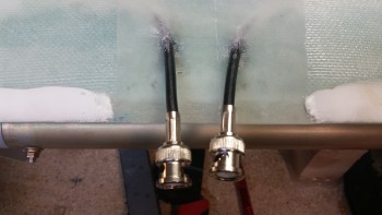
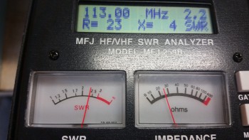
I then checked the VSWR of the VOR/LOC antenna using the MFJ-259B Antenna Analyzer, which read 2.2. A VSWR value of 3 or under is acceptable, so I’m very pleased with 2.2 VSWR value. Unfortunately, since the center frequency of the glide slope antenna is 345 MHz I couldn’t check the VSWR for that antenna on this meter, so I’ll figure that out later. [If you’re wondering what the heck VSWR is, check out Jim Weir’s article in the Dec 2013 issue of “Kitplanes”… where he explains it very well].
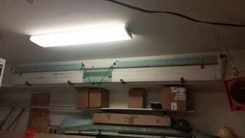
With the antenna cables terminated, I then remounted the canard with attached elevators back onto the upper shop wall.
•••