
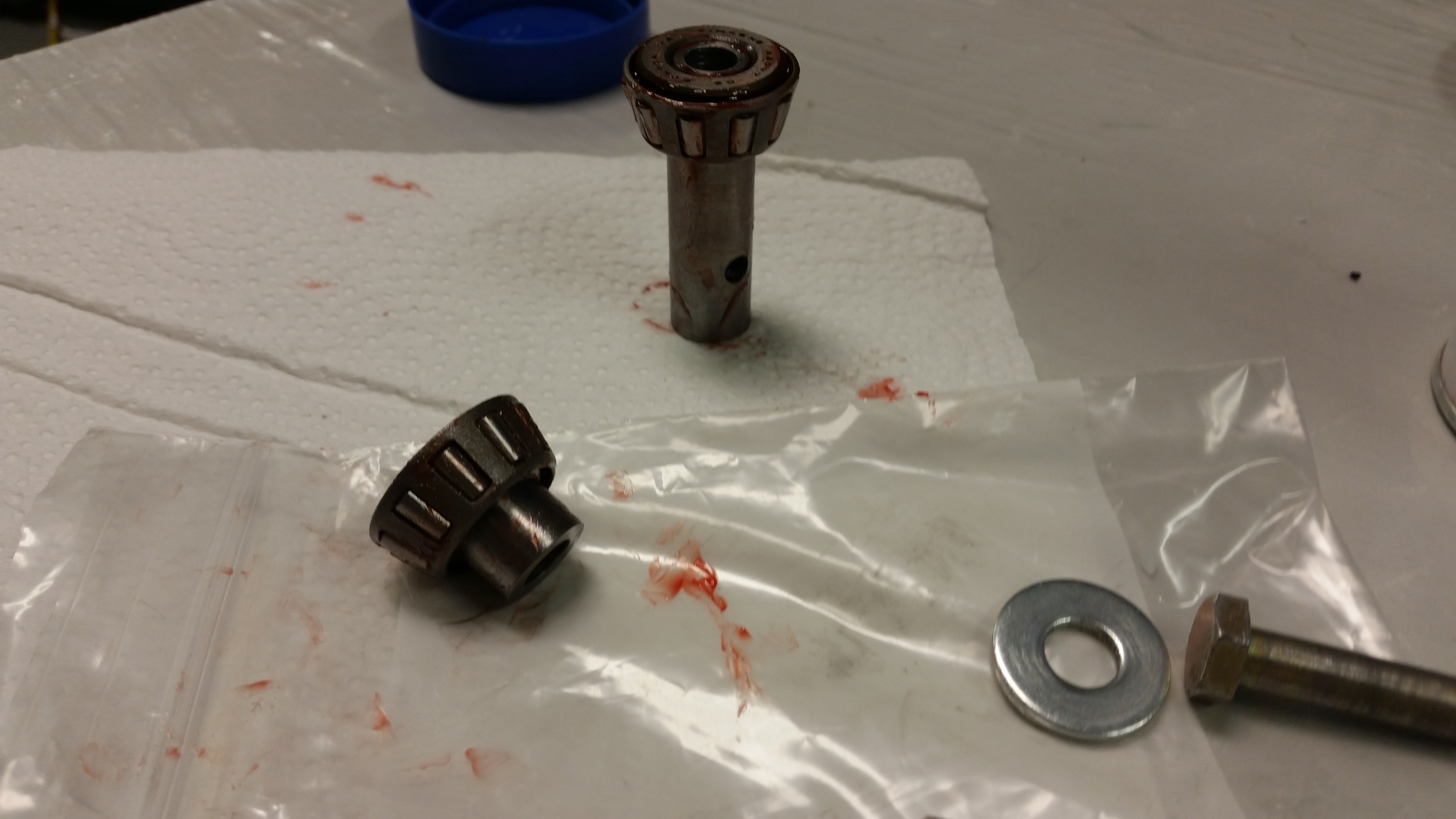
Since I had to remove the NG6B and gear strut assembly to glass the inboard F1-3 bulkhead (“Napster”), I started off today by greasing up the NG6B bearings.
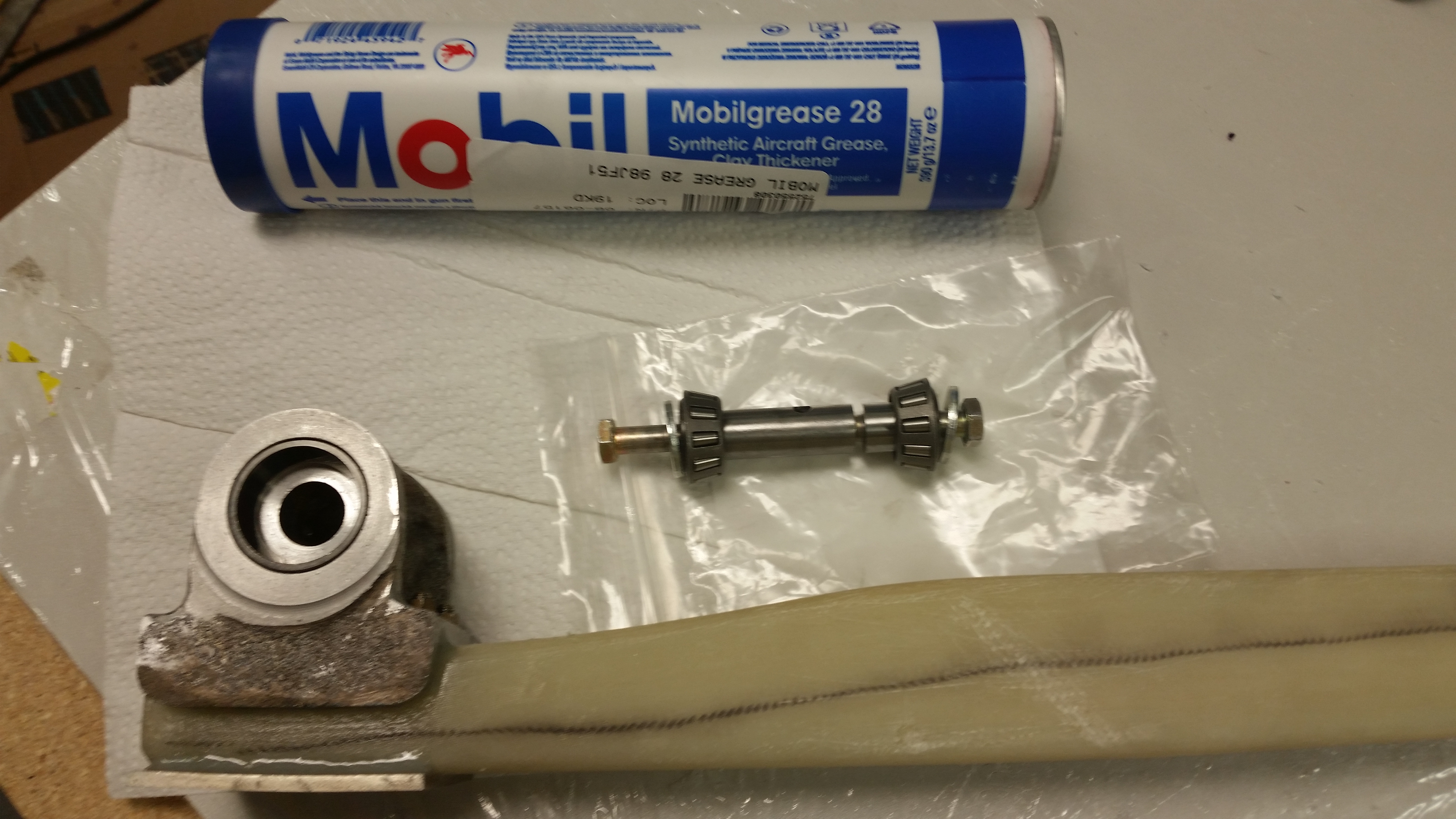
Here’s an action shot of me greasing the bearings!
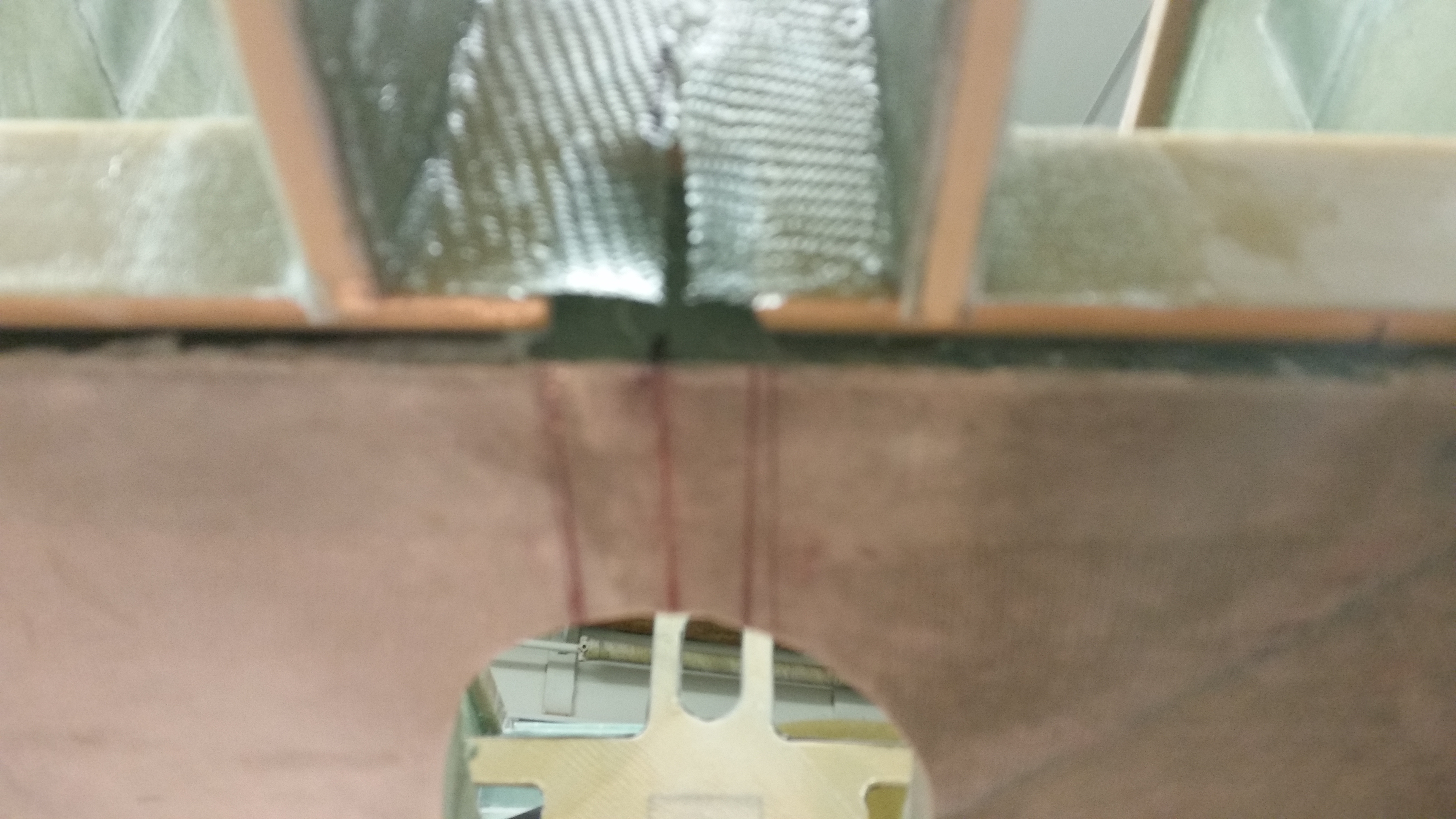
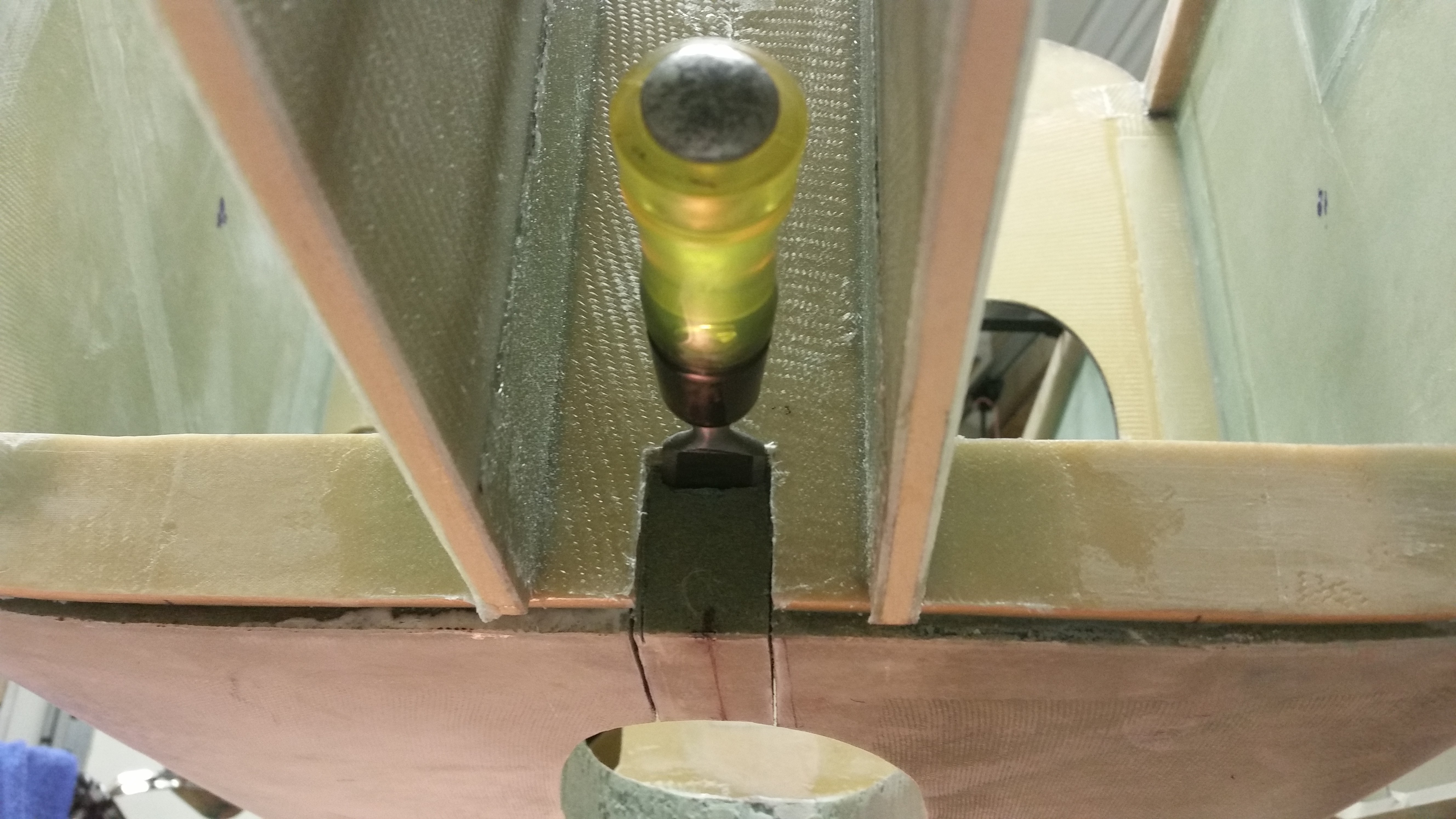
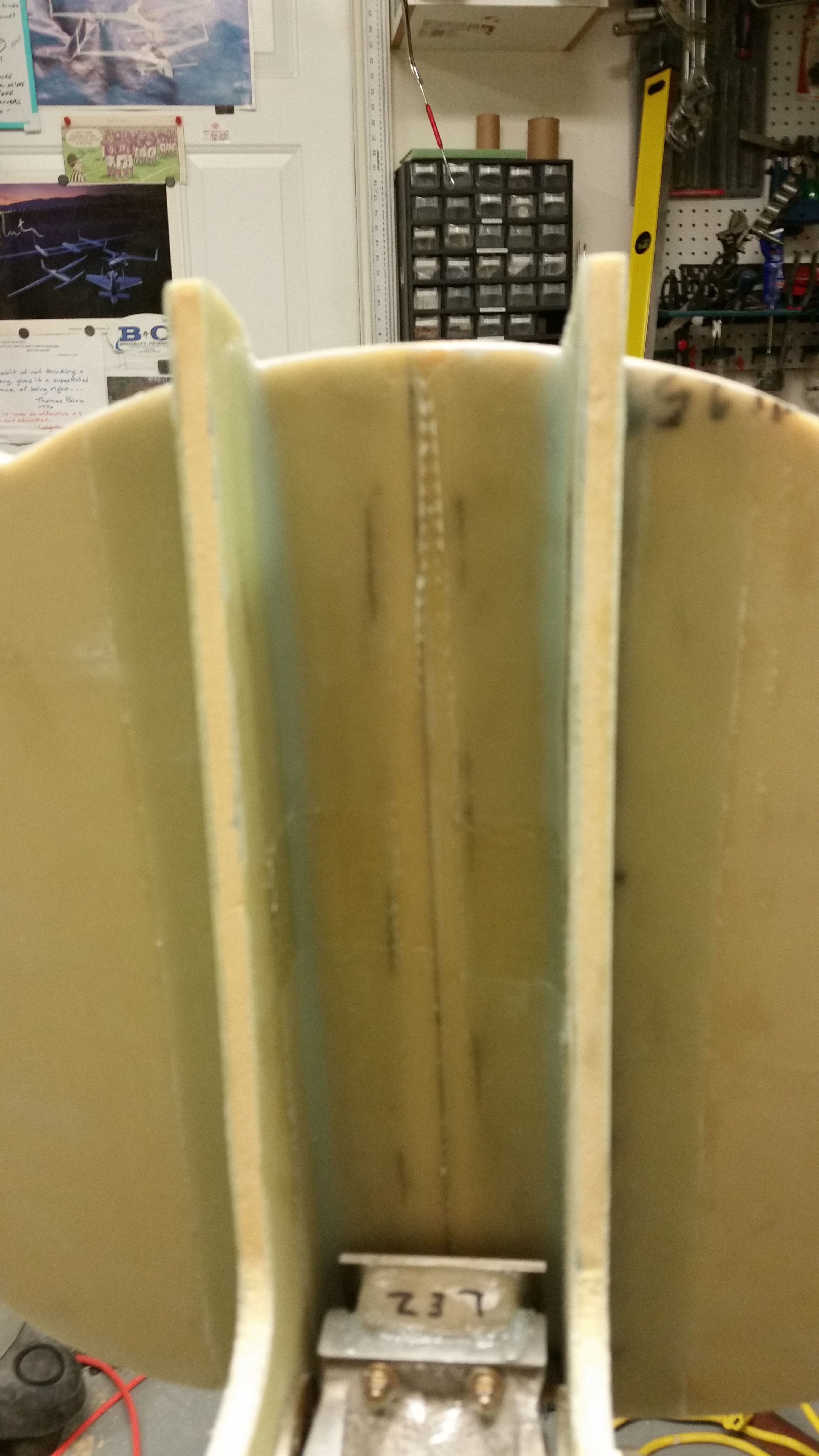
I then started on the gear strut channel that runs from F22 aft to the wheel well. The first task was to mark the cut lines.
I then cut the lines with the Fein saw.
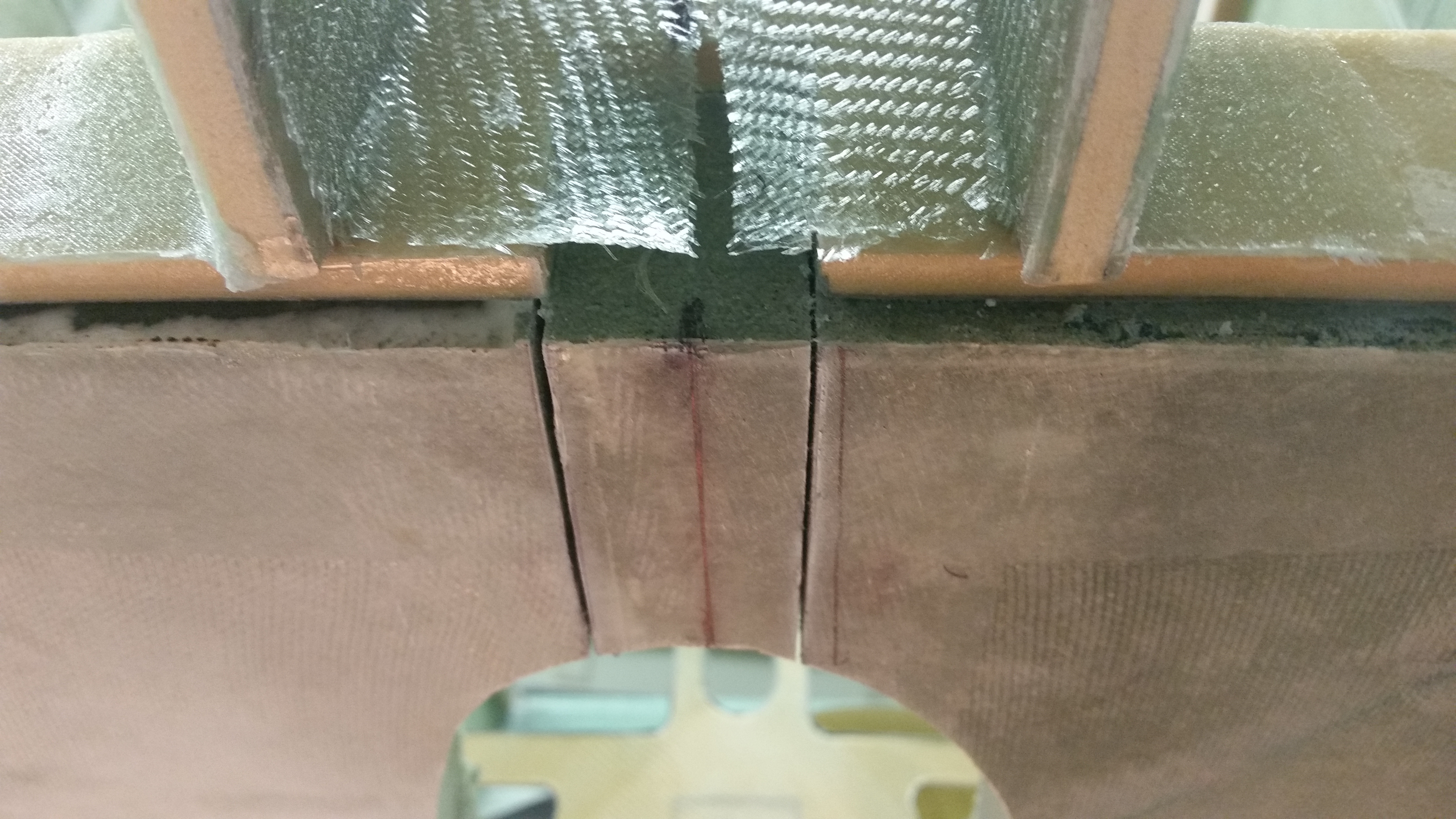
And cleared out the dead glass, foam, etc.
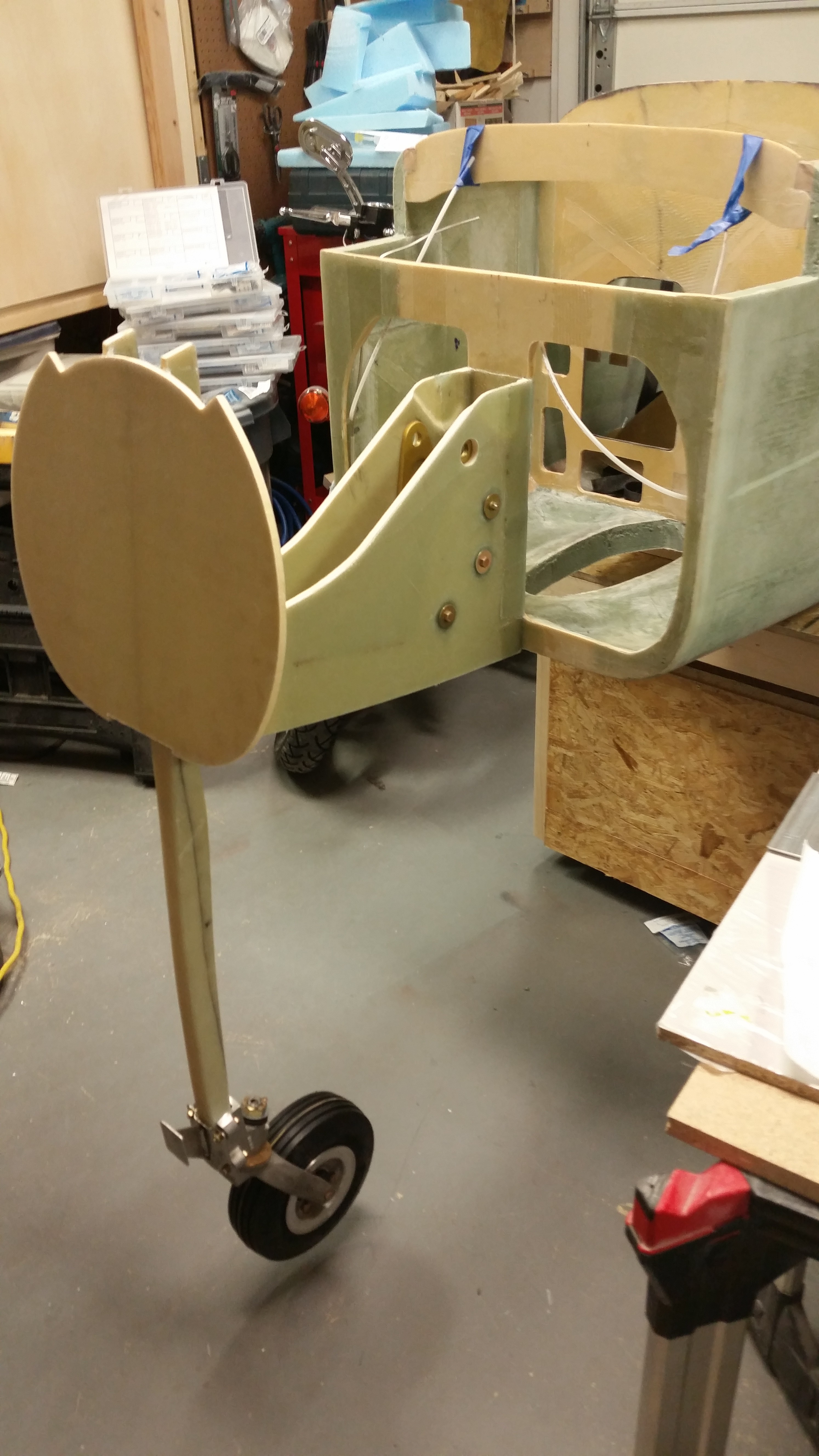
Here’s a shot of the nose wheel spacing.
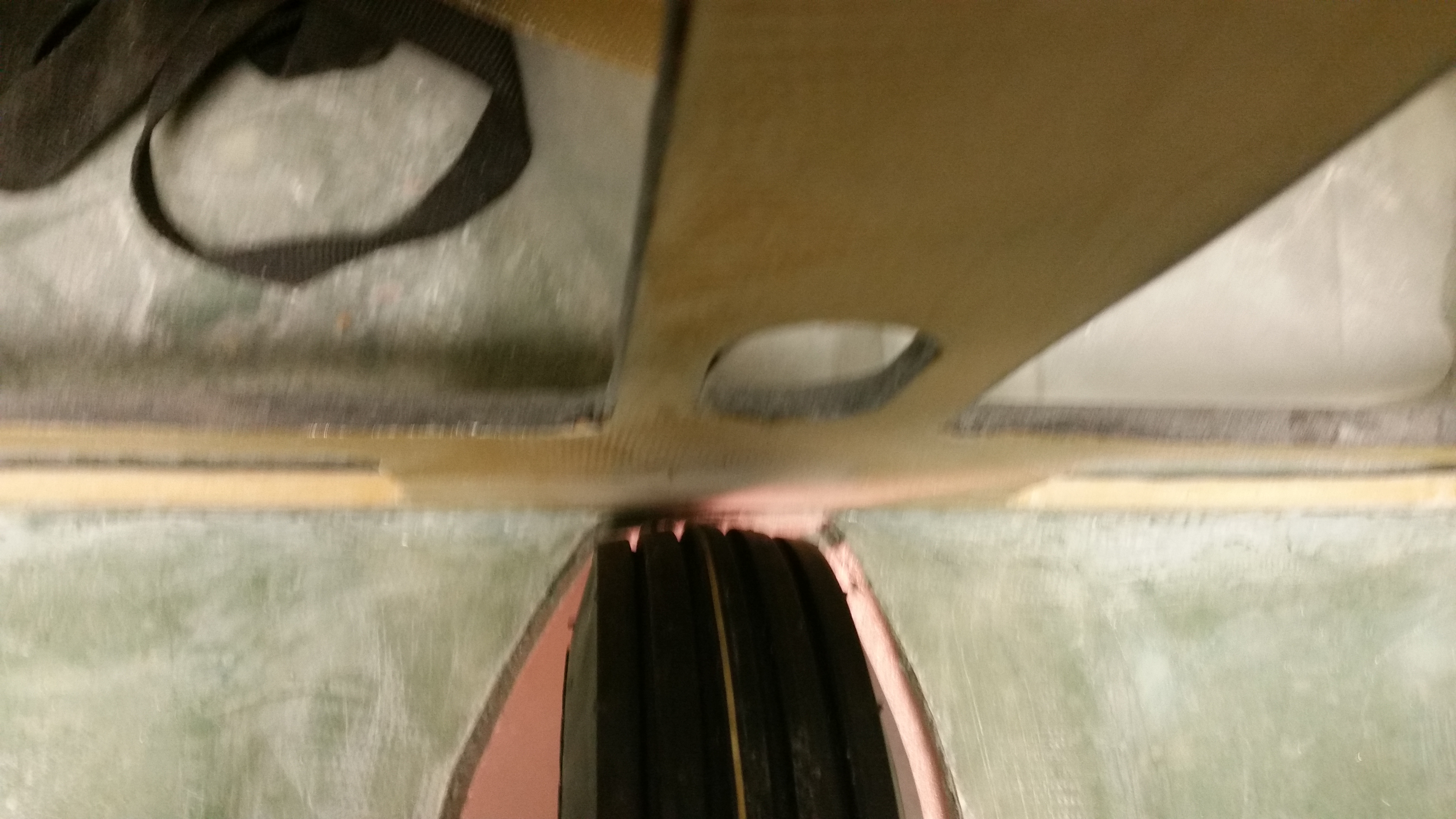 Ok, some of my fellow builders have discussed the issue of the stock nose wheel sticking out down below the bottom of the fuselage, normally around 1/4″ to 1/2″. Fortunately, I don’t have this issue on my bird, and it’s all really because of a serendipitous reason.
When the foam called out per CP 34 back in 1982 changed from the old PVC to the now standard Divinycell, the foam for the fuselage bottom changed from 1.6″ to 1.75″ thick. Thus, when I built the F22 to the plans height dimensions the fuselage bottom ended up almost 0.2″ lower than the bottom edge of the F22. I don’t remember all my reasons for doing so right now, but I didn’t sand the bottom fuselage surface to blend into the bottom of F22 (you can see this in a couple pics above). One reason I left the bottom fuselage foam at 1.75″ was so that the entire nose structure would be a bit lower.
Now, let’s fast forward to a few days ago when I mounted the NG30s to the front of F22. To keep the bottom of the fuselage even, I dropped the NG30s even with the fuselage foam. Obviously when I did this it dropped the Water Line (W.L.) of the nose gear pivot down by about 0.2″. This time around, I was hoping that the lower fuselage/nose gear box would result in an angle that would avoid any further messing around with the gear strut, etc. to fix a less than shy nose wheel.
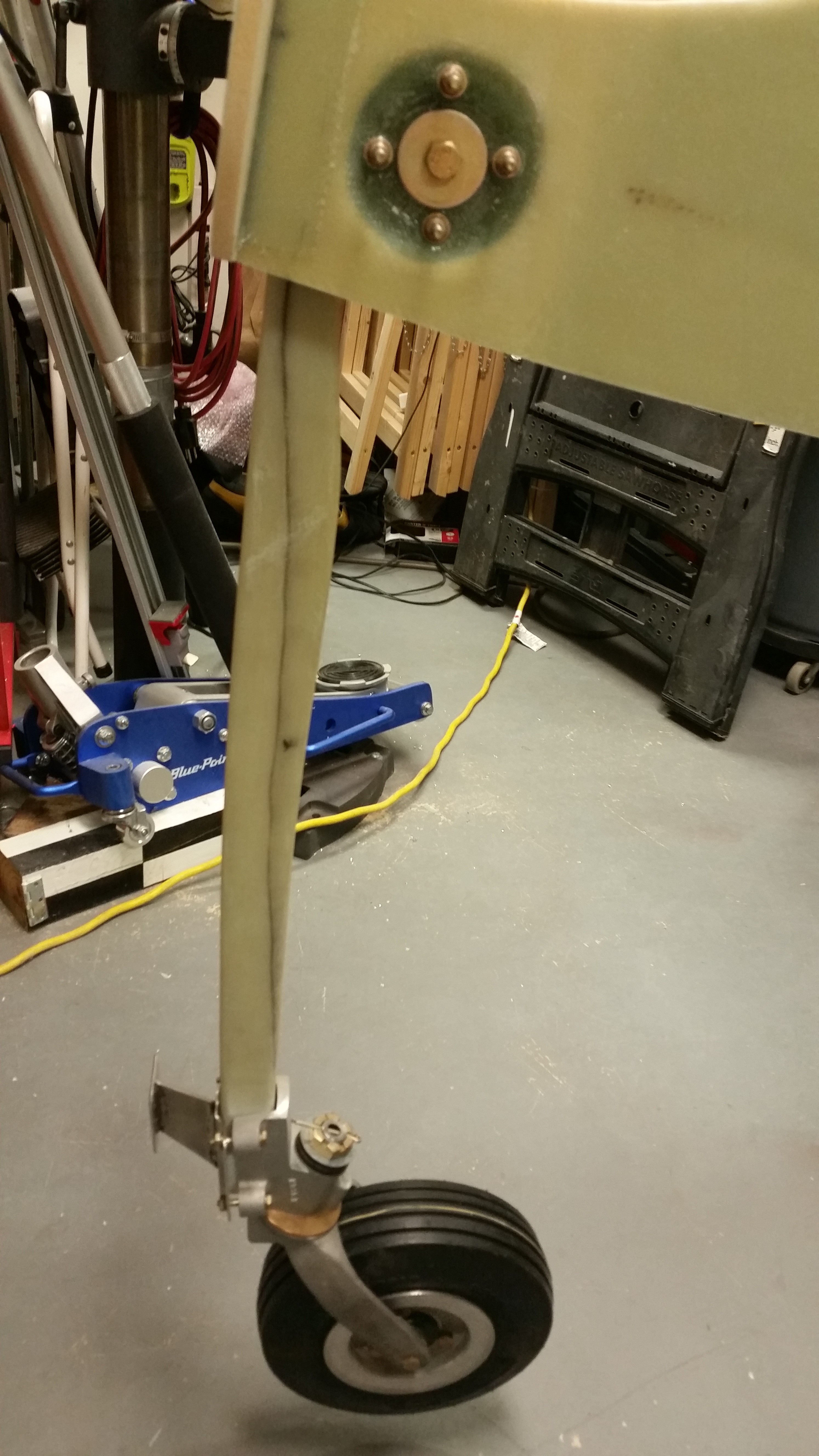
Well, it did. When I cut the nose gear strut channel, mocked up the nose gear, and checked the spacing of the wheel in the wheel well I was pleasantly surprised that with a stock gear strut channel (read: no more cutting or layups) my nose wheel sunk out of sight into the wheel well.

Of course, with the wheel sinking deeper (meaning up) into the nose wheel well it means that the standard nose wheel cover (NB) isn’t deep enough and will have to be increased height-wise.

Here’s a shot of the nose gear in the wheel well.
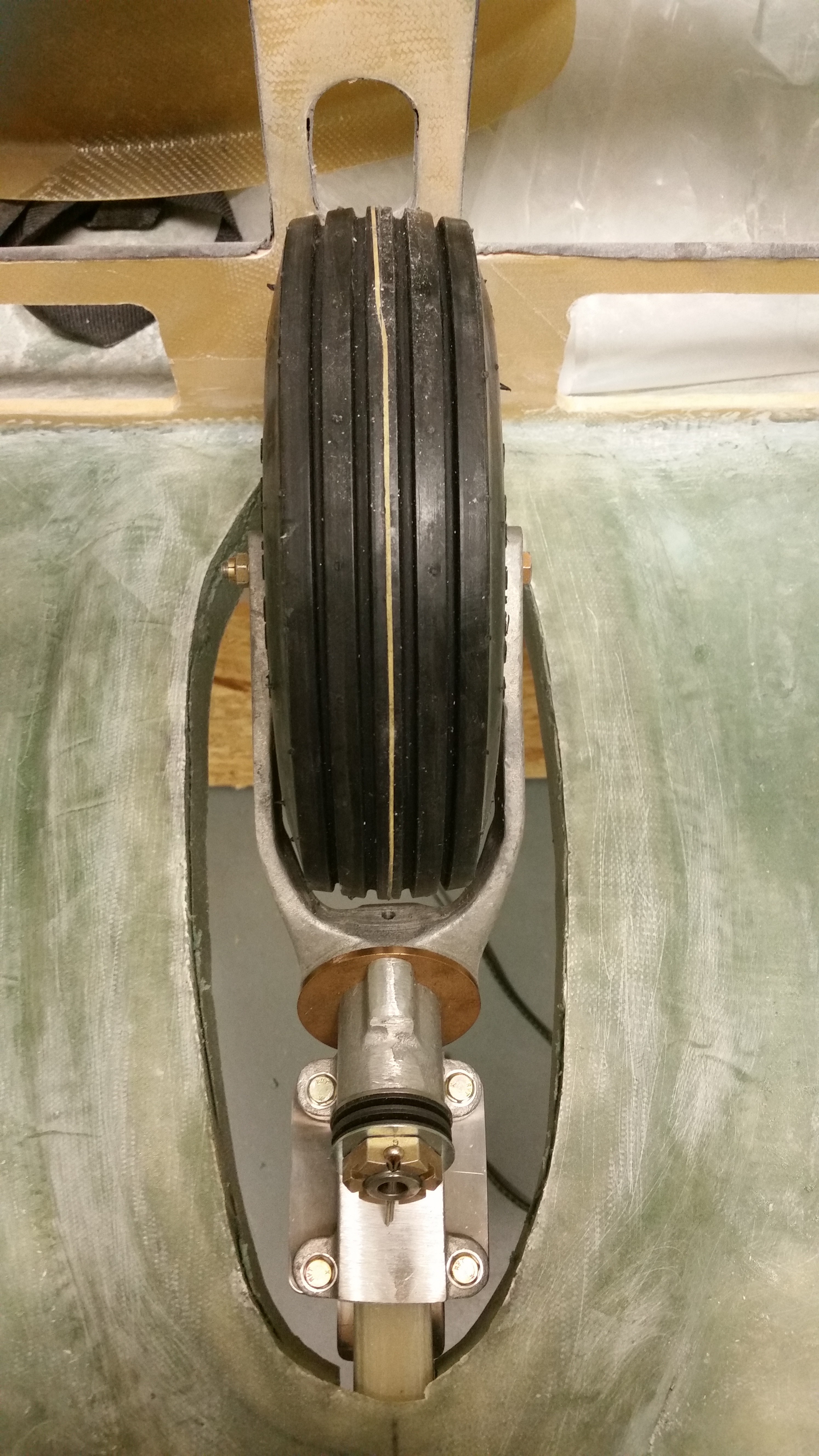
And a couple shots of the nose gear strut mocked up [Note that I removed the temporary NG6B shipping bolts and installed the final AN5-15A bolts and AN970-5 washers when I remounted the gear strut].
I also pulled the peel ply from the inboard BID tapes holding Napster to the NG30 uprights.
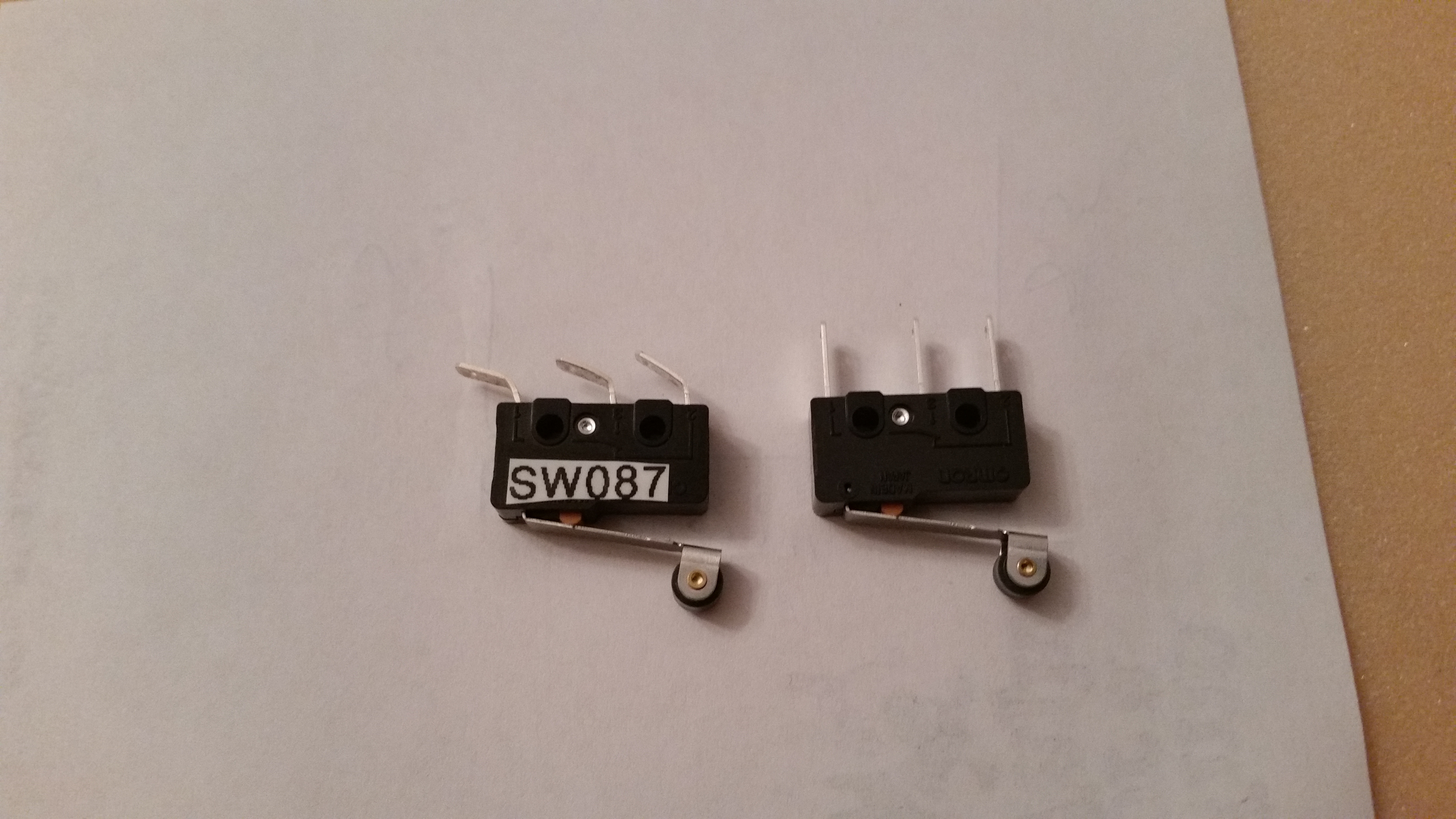
I then prepped a microswitch for mounting on the nose gear actuator as a part of the nose gear warning system.
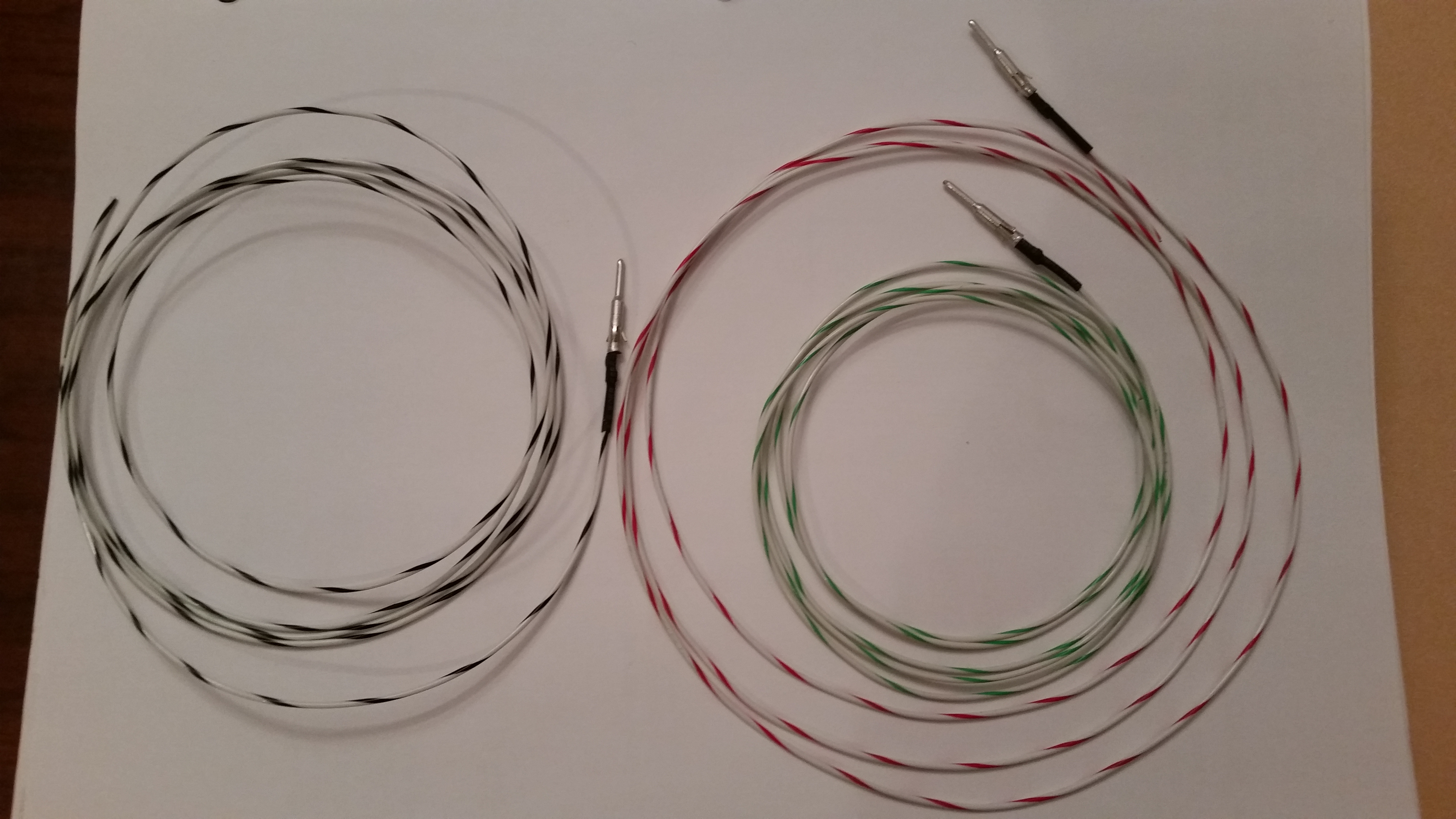
I crimped up some 22 AWG wires for the nose gear warning system. These wires will be ran through the bigger AMP CPC connector that I recently ordered from Mouser.
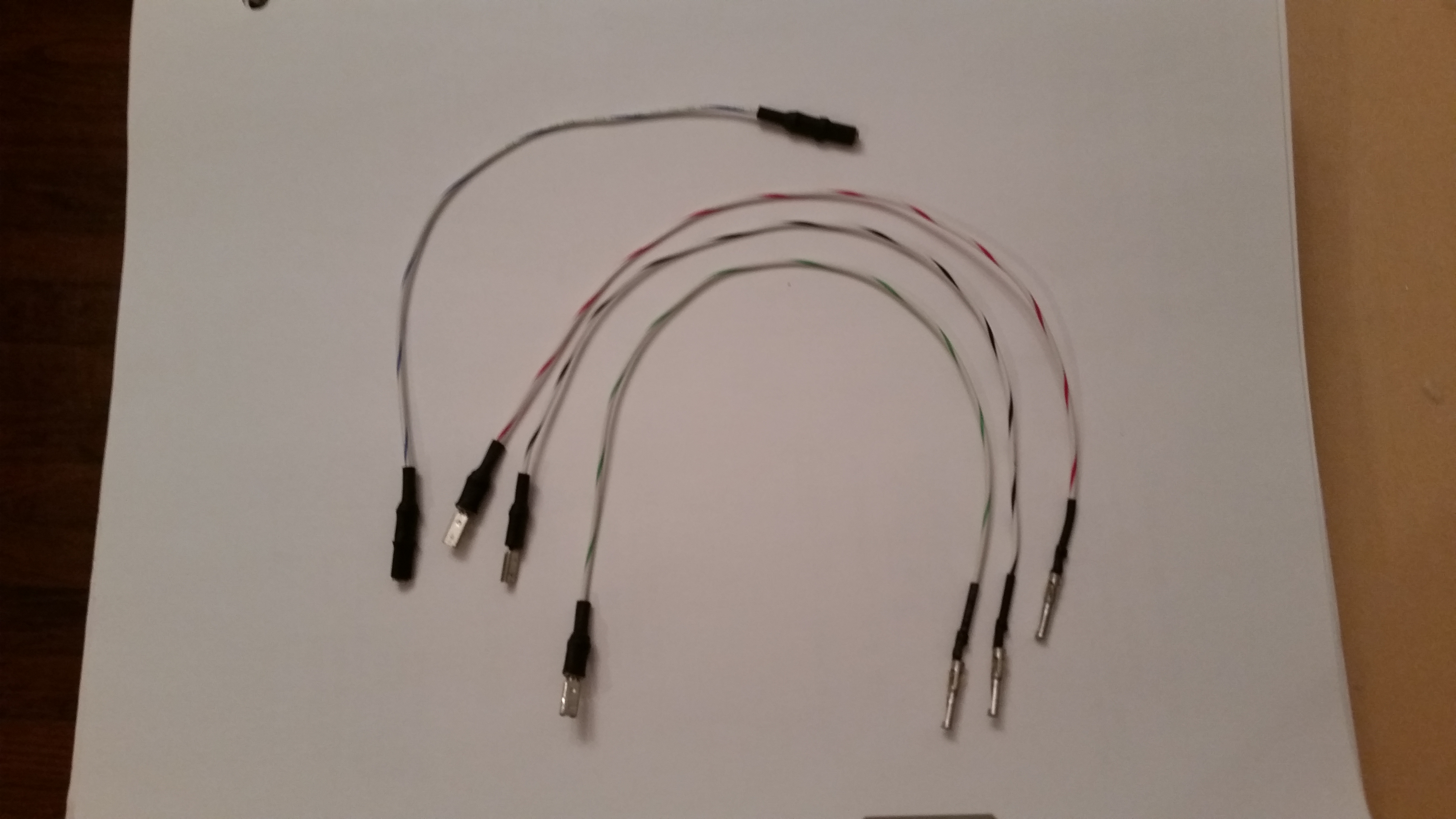
These wires are also for the nose gear warning system, but they mount into the opposite side AMP CPC connector and will terminate at the gear & canopy warning module.
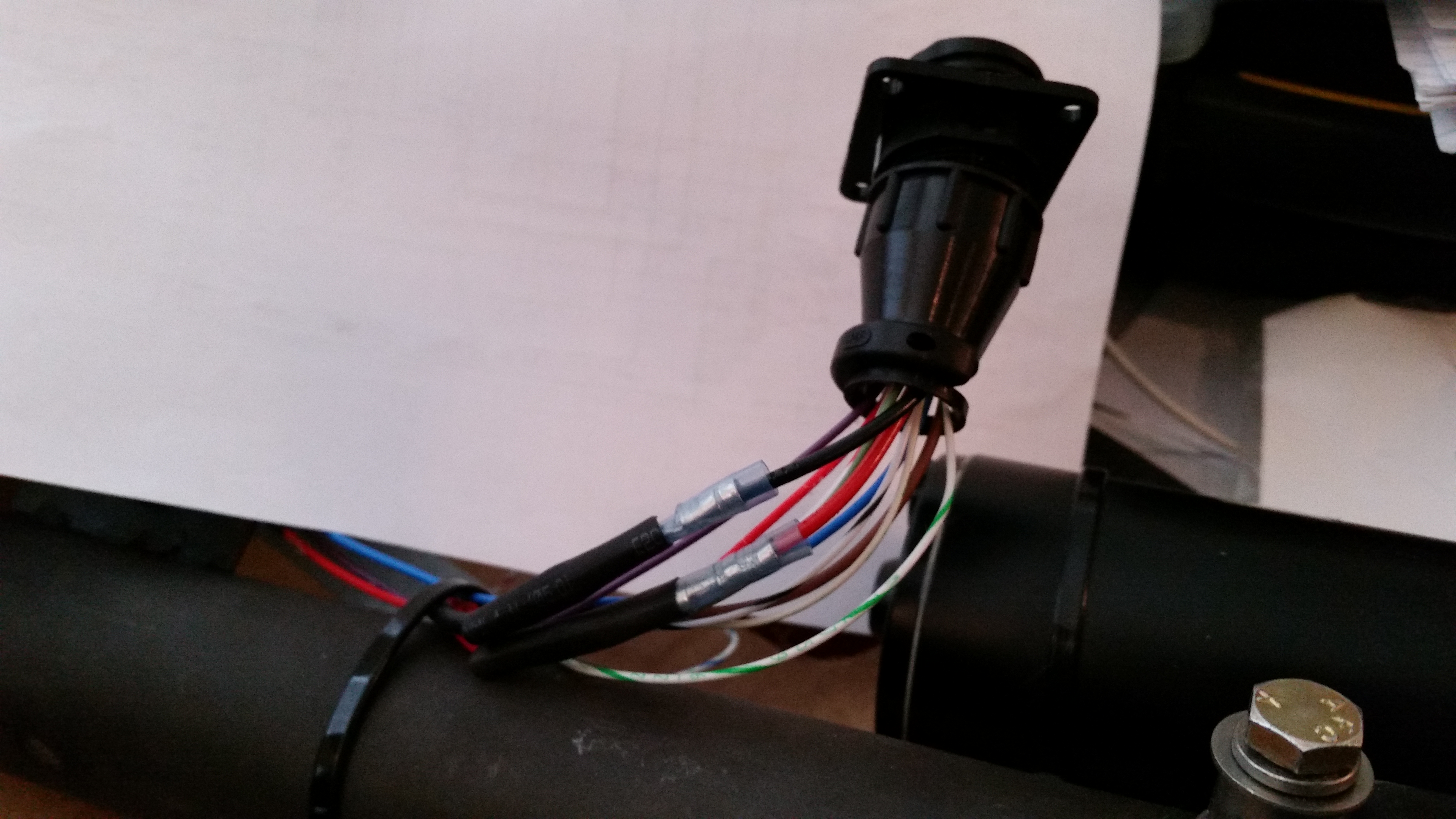
I also took the opportunity to re-terminate the socket connectors that come from the nose gear actuator side of the P1 connector.

Here’s a shot of the P1 connector. After I confirm that all the connections are good I’ll zip tie the wires and permanently mount the cable clamp.
Also, the two power 12 AWG wires (Red & Black) coming from nose gear actuator motor in the end were just too big to fit into the back connector plate. I tried slightly expanding a couple of connector holes with a #29 drill bit to start out with, which worked well. In the end though, I finally threw in the towel and ended up chopping off the last 3″ of the power wires and replacing it with a 3″ piece of 14 AWG wire. You can see the connectors in the picture below where I spliced the new wires into place. After messing around with the unruly wires, it was great to work with wires that simply went where they’re supposed to!
Tomorrow I plan on getting the wheel assembly mounted to the gear strut. Since the nose requires a lot glassing, I’ll try to fit in work on the elevators as stuff is curing.