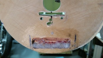
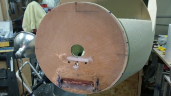
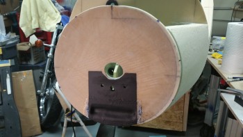
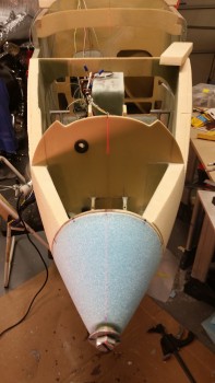
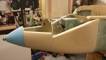
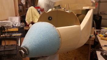
You’ll see later in the post what I started off with the first thing today on the Long-EZ build. I was scratching my head on just what was the best way to make a 3″ wide x 1″ high depression into the face of the F-7.75 bulkhead to provide clearance with the bottom aft edge of the landing light.
I finally decided that given how hard the Finnish Birch plywood is, especially with a couple of layers of fully cured (read: years!) glass, I’d better call in one of the big guns. I grabbed my Bosch router, threw in a rounded bit and went to town. It didn’t come out half bad, but I did have to repeat the process one more time to get the light to fit. And the light did fit. Yeah! (“And there was much rejoicing . . .”, said in Monty Python voice).
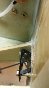
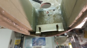
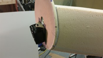
However, there was still a problem with the landing light mounting bracket that had to be contended with. If you look at the pic below, there was a massive number of spacers that were required to get the landing light aft enough to where it wouldn’t impinge on the line of the outer nose skin, or the light lens cover.
I had some options, but I wasn’t too keen on any of them: I could simply do nothing and live with the spacers, but that wasn’t clean and I hate wasting space, even if I don’t have a plan for it (I have a plan for that space, but I don’t think that bracket would effect it). I could bend the bracket, and then cut it off about half way of the current vertical part, but then that would certainly mean drilling more holes into the bulkhead, and bending it exactly right and still getting the same exact configuration could certainly be done, but I could see where it would be at least a fair amount of trial & error on the good hand, and just down right problematic on the bad hand.
I decided to keep the above options open as options B & C, and for option A I would try out a piece of 1/8″ thick x 1″ wide angled 2024 Aluminum. Now, make sure no kids are around, because once again I committed a cardinal sin . . . I bent 2024 aluminum! I know, I know … I’m outta control!
Let’s get to the pics.
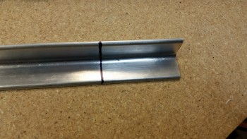
Here I marked the angled 2024 at 2.6″ wide.
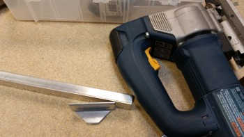
I figured while my piece was still, “on the rack,” if you will, that I’d cut my 45° angled cuts first using my trusty jig saw (BTW, REAL men use jig saws to cut 2024 aluminum . . . haha!)
I used a regular trigger clamp with the angled aluminum set in at an angle to squeeze the sides to obtain a minimum of 11 degrees. I was able to get about 5° with the trigger clamp. I then dug out my small vice and tried that. I got another 1°, maybe 2° out of simply clamping it in the vice. It was time to use the nuclear option. I grabbed my 5-pound sledge hammer and the heat gun. “Go ugly early, or go home!” Right?!
I heated the 2024 angled piece for about 90 seconds, then rapped it sharply with the sledge. Check angle. Repeat. I did this about 3 times and needless to say, I not only got my 11°, but a couple more just for pride’s sake! (I jest, it just happened to come out at 13°).
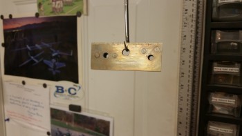
With the long pole in the tent resolved with my new bracket: the angle, I then drilled the top mounting hole and then the backplate wire access hole.
I drilled the 2 #10 holes in the bracket above matching the top 2 holes from the previous bracket, although I apologize since I failed in taking a pic of that.
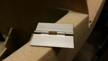
Since I’m going to use the very last scant few ounces of Alumiprep that I have to Alodine the bracket, I figured I would go ahead and whip up the hinge for the TAXI LIGHT… separate taxi light that is dear readers!
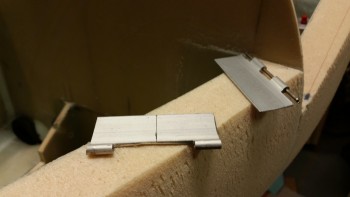
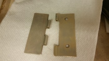
After I cut the hinge off the long hinge stock, I cut out the middle tab.
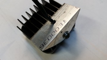
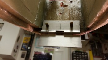
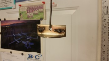
You can see the middle tab missing a little better here in the pic below. I did this to allow for a torsion spring to be mounted on the hinge pin and be secured in place by a screw on the lower hinge and compression against F-7.75 on the top side. See the next pic to see how it gets mounted.
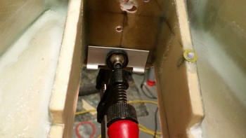
Here I’m mounting the top part of the taxi light hinge. Since the landing light is a very focused beam point down at about 13° currently, it won’t really suffice as a taxi light. I will have wing mounted lights, but I had already planned for a separate taxi light and just needed the place to put it. Well, har she be! Just forward of the main battery.
The plan is to link the taxi light to the NG6B via a cable. When the front wheel goes down, guess what automatically pops out? Yep, my . . . taxi . . . light. (Do you hear angelic voices?? something?) I’m still finalizing the wiring circuits, but it will most likely be powered on/off via a microswitch that it itself will trip.
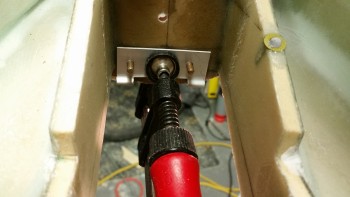
I then drilled the holes for the screws, repurposing the lower 2 holes that I had previously drilled for the “old” landing light mounting bracket.
Here’s a close up of the taxi light hinge & mounting screws.
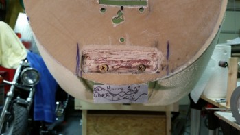
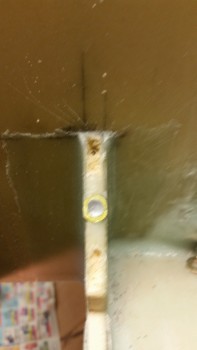
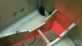
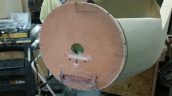
Ok, here’s the depression I made in the F-7.75 bulkhead first thing today. You can see the screws for the taxi light hinge towards the bottom of the depression.
I slathered up the taxi light hinge screws with pure flox and also filled the hole immediately above the depression.
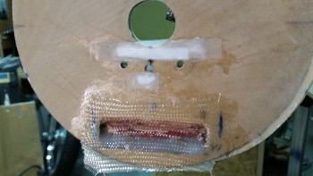
I then laid up 1 ply of BID over that hole and the depression to help both secure the screws in the flox better, and to cover up the exposed wood that has a higher probability of moisture being at the front of the plane, and considering their will be small intake and exhaust vent holes in the lens cover for landing light cooling.
I mixed in a bunch of micro with the bit of flox I had left over & filled the old landing light wire access hole and the slot where the landing light mounting bracket traversed F-7.75.
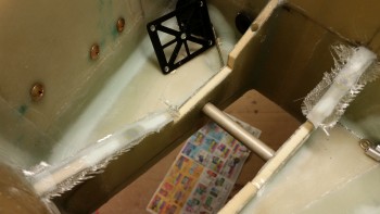
Since I still had some flocro left over, and some pure epoxy, I went ahead and dug out the edge foam of the BC1s on each side of the Rivnuts I installed in the BC1s a couple days ago.
I then laid up 1 ply of glass just on the top edge to give the Rivnuts strength, and so that they are less prone to pop out later on.
Here’s aft left Rivnut just forward of the Napster bulkhead.
And here are both of the Rivnuts I covered with 1 ply of BID tonight. As you can see, I still have a hole for a third edge-mounted Rivnut, but I ran out of RivNuts and will have to wait until I receive my next ACS order to install it.
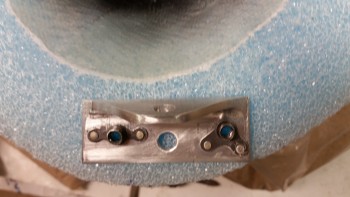
Circling back to the new landing light mounting bracket… I made it “New & Improved” by adding nutplates! I know it’s bad form to mix nutplate styles or to install nutplates at different angles to each other, but I miscalculated my dimensions slightly and didn’t have enough edge to mount the second rivet, so I simply used a 90° nutplate instead! (Trust me, whether it’s laziness or pragmatism, I wasn’t about to make another bracket just to allow for a better fitting, aesthetically pleasing nutplate…especially when this thing will be buried in the nose cone).
I then Alodined the landing light mounting bracket and the taxi light hinge using the very last drop of Alumiprep that I had, as I mentioned earlier. In fact, since there wasn’t actually enough Alumiprep to even cover all of the landing light bracket, I put just a little bit of water in the bottle, shook it really good to get all the Alumiprep juices possible extracted from the bottle, then poured that in the little plastic bin as well. Yeah, when I said I was low, I mean I was really LOW…
Jumping ahead almost 2 hours, here’s the air drying Alodined landing light mounting bracket. I left the parts in the Alumiprep solution for about 40 minutes, which was actually a tad too long because I had to scrub all the dark “soot” off the parts before dunking them in the Alodine. Regardless of my decent success with the Alumiprep, I knew the parts needed to soak in the Alodine for well over an hour, which they did.
I’ve never Alodined hinges. I know some folks do & others don’t. I’m not sure if it matters but they came out pretty nice . . . for such weak Alodine, not bad.
While the parts were soaking in the Alodine solutions, I went ahead and pulled the peel ply, razor trimmed and cleaned out the threaded holes on the Battery Compartment Rivnuts. And then, not being entirely pleased with the curing progress on the front side of F-7.75, I set up a heat lamp to motivate the BID layup to cure faster.
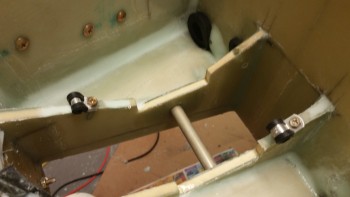
A little while later, I turned the heat lamp off for a bit to check out how the Adel clamps would work in the RivNuts when I get around to installing them. Here’s a shot of them installed. I’m very happy with angle and position of these Adel clamps. As you can tell, I’m very big on wire & cable management, most likely from the time I spent as an IT project manager in the Air Force.
Well, the heat lamp did its trick and finalized the cure for all the stuff on the face of F-7.75.
I took the nuts off of the embedded screws and the double-checked the spacing of the screws by remounting the top hinge piece. It all looked good.
I then sanded the layups and the face of F-7.75 in preparation for painting, and reattaching the nose.
I taped up the entire forward bulkhead except the area where the landing light will be, and thus be somewhat visible through the landing light cover lens.
Then, just as before, I sprayed on 2 coats of black paint.
I then mounted the landing light for the last time in what I hope will be a very long time! I used a very small dab of blue Loctite on each screw.
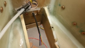
In addition, one thing that isn’t visible is that I put 3 layers of heat shrink on the first inch or more of the already covered bundle of wires. Since I couldn’t get a grommet in there with the way the mount was configured, I figured 3 layers should do fairly well. Of course this will be an item that I check on my condition inspections.
One item of note is that when I slid the wires through the new hole I drilled in the bulkhead, it was fairly tight. I think this tight fit in the wood hole should act as a natural grommet keeping the wires secure from vibrating or flopping around.
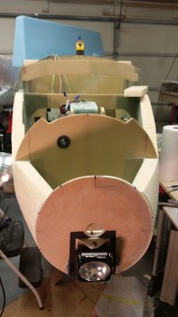
Here’s a front view of the light. I did a final check on the angle, and it’s sitting right at 13°. Since I have a nose taxi light and will have wing lights too, I’m absolutely happy with 13°. I also pulled out the square and checked each side with the bulkhead… perfect at 90° left & right. Time to button this baby back up!
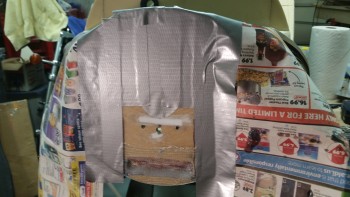
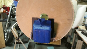
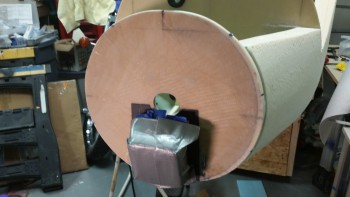
I placed a very soft paper towel pad over the light lens and then taped up the light with blue painters’ tape. This is taping round #1 and is designed for ease of getting the tape off of the LIGHT. I also buddy tabbed each end of the tape to help in the removal.
Taping round #2 was to protect the blue tape from nasties that may try to impinge themselves onto the light, so I used duct tape. I also buddy tabbed these pieces as well.
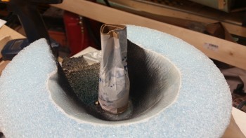
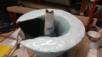
I then made a guide / gunk protector for the G10 sleeve nub housed inside the innards of the nose cone. I tested it out and it will have to come out fairly soon because it essentially extends the G10 tube which then interferes with the very tight clearance of the screw head for the landing light. I’m telling you, this clearance stuff is down in sub 0.1″ level easily!
It was go time! I took a deep breath, whipped up some epoxy with fast hardener, used a dash of Cab-O-Sil that it would help with the vertical stickage, then I added about 20% flox and 80% micro. I wanted it a little pasty with the flox so that it wouldn’t tend to run. I also applied a little less on the top ring so that it wouldn’t want to run down into all the internal goodies of the nose.
I then mounted the nose first with my cardboard guide tube, then I pulled that & inserted the mojamma bolt and tightened it just a hair. I then started scooping up some micro, but it wasn’t overly messy . . . very manageable. I then checked my tick marks and very slightly realigned it, tightened the bolt a hair more, removed a little bit more micro around the edges . . . and repeated a couple more times. Scooped a little bit of micro from the light bay on the left side, but not enough to have me concerned.
Then, for a final cross check, I set up a laser shot and confirmed it was all spot on.
Ah, Deja Vu! Only now I have my lights & pitot tube squared away!
And one last shot. I think that angle will stop looking weird to me when I get the top part of the nose on.
Tomorrow I’ll be working on the prep stuff to get the external nose glassed. Which means round 3 of sanding as well. Either tomorrow evening or on Sunday I think I’ll be flipping the bird!
Finally, on a more serious note, as I was doing some research tonight, I ran across some sad news. It’s with a strange sense of irony that I tell those of you that may not have heard that Bob Davenport, the super smart engineer that designed the nose that I’m currently working on –and that me and just about every one of my building buddies have installed on our planes– passed away in mid-October. Here’s his obituary. I went back and checked the latest CSA newsletter and sure enough it was in there. I think I missed it because I was keyed in on Joe Caraggio’s first flight. Bob was quite a fascinating guy and did a ton for our community. I’m sorry I never got to meet him.

