
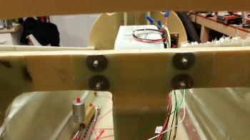
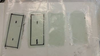
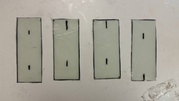
Here’s the shot I promised of the trimmed voltage regulator click bonds that I finished up yesterday.
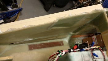
And here’s a shot of the cured right side nose panel layup after I pulled the peel ply.
I wet some paper towels with white vinegar and then used clothes pins to secure them to the exposed aluminum brake lines to clean off all the epoxy gunk.
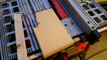
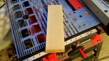
I then set up my small table saw just outside the garage to cut the H100 foam down to 3″ wide. I’ll be using this piece for the center foam between the BC1’s when it comes time to install that foam.
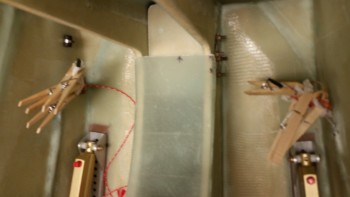
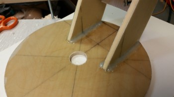
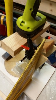
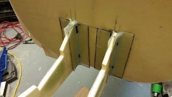
I then mocked up the clamp setup for attaching the BC1s (NG30 continuation tabs) to the aft side of the F-7.75 bulkhead (the last & most forward of all the bulkheads).
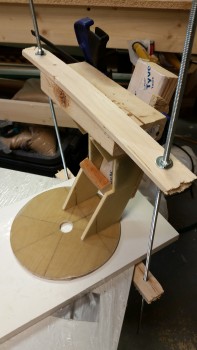
To figure out exactly where the BC1s needed to be mounted to the F-7.75 bulkhead, I reviewed the plans to get my bearings. I then found and marked W.L. 10 for a good reference point. After that, I was off to the races. [Note in the pic below that I drew reference lines next to each BC1 where it met the aft side of F-7.75 . . . this will come into play here in a moment].
I whipped up some flox using fast hardener & applied to the front edge of each BC1 in their clamped configuration… to keep them 3″ apart, just like the NG30s.
I then lined up the vertical lines I had drawn out and the W.L. 10 side marks.
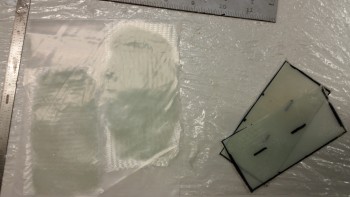
As the flox was setting up a bit, I prepregged 4 x 2-ply corner BID tapes to layup on the inboard and outboard of both BC1’s.
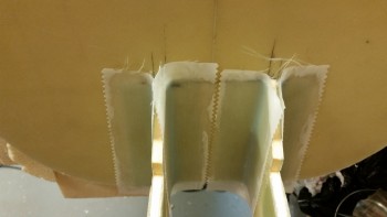
Ahh, here’s a great shot. Everything going nice and smooth . . . then . . .
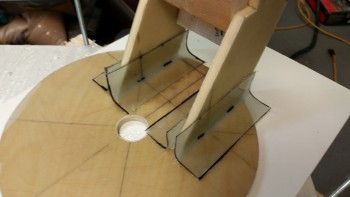
Well, it all sorta just went to hell after that! Every aspect of this layup looked perfect, EXCEPT, when I was checking out how level & even the 2 BC1s were, I noted that the very back bottom corner of the BC1s didn’t match. They were probably around 0.2″ off in elevation! What?! Everything else looked so perfect . . . I wondered if I had actually cut these things wrong, but then recounted the countless times I held them next to each other and they were a perfect match.
Something was up!
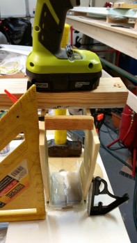
After messing with one issue: that I had simply clamped them slightly askew with the left-to-right clamp, I then also realized that my threaded bolt clamp was being a real PITA to dial in and was also causing issues. I chucked the threaded squeeze clamp … literally!
All in all, I just couldn’t get the clamps to work. I essentially did the closest thing to free handing it as possible, using one small clamp, a 2×4 piece and a drill for a weight. With that, I was able to get it pretty darn close.
One issue that I had, that I referenced above, was that I made all my vertical reference markings only as long as the front of each BC1. When I added flox fillets in the corner, guess what?! Yep, all but the very back end of the line was obscured from my view! So the multiple times I had to literally peel up the layups to check the marks just gummed up things even worse.
Of course, after much consternation and a liberal use of the highest grade military expletives, I finally got an acceptable layup out of it. The time factor was not good though and extended my evening quite a bit.
Since my dream layup turned into the wrong kind of dream: a nightmare! I decided to something more at my skill level . . . ha! Mainly because I had epoxy & flox left over, I went ahead and glassed in the upper draft plate. I will say that I used scrap BID and didn’t prepreg it … wow, talk about a REAL nightmare! I can’t imagine building a glass bird without using prepreg. Clearly, I use it A LOT!
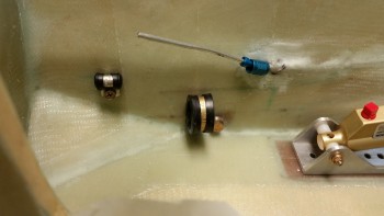
With the BC1 attachment & upper draft plate layups curing, I then went to work on first cleaning up all the peel ply boogers from the right side nose panel layup, then drilling out the bolt holes and attaching all the sidewall accouterments. After the rudder cable bushing (AN111-3) and assorted Adel clamps were mounted, I then mounted the right rudder pedal.
Success! The rudder pedals are official in! (yes, “IN,” but not complete since some rigging has to be accomplished).
Here’s another shot of the installed right side rudder/brake pedal.
And here’s a shot of the brake line Adel clamp (small one to left), the forward power cable big Adel clamp, the AN111-3 rudder cable bushing (immediate right of large Adel clamp).
I placed the brake line AN fittings on the brake line so I don’t get flamboozled working on something else and forget to put them on before flaring the line. With not a lot of line to work with, I don’t want to make any silly mistakes here.
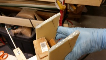
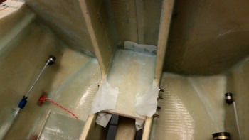
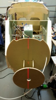
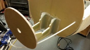
I pulled the peel ply on the BC1 layups while the glass was still in the green state. It was a bit gummy, but definitely cured. After razor cutting all the glass and cleaning the layups, I mocked it up on the existing F1-3 (Napster) bulkhead.
To get a better idea of what I was working with, and to handle an awkward component, I drilled a “toenail” hole in the top of each BC1 into the face of Napster. This was of course after I spent a few minutes dialing in the exact location of the BC1s/F-7.75 mounting to Napster.
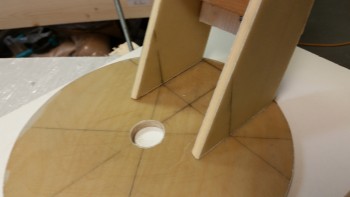
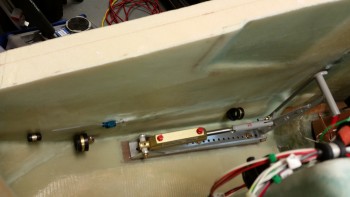
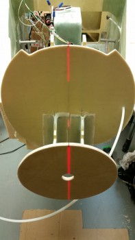
I then took my laser and shot it down the aircraft CL. Ahh, not so good Grasshopper! The CL of the F-7.75 BH was about 0.5″ to the left (right in the pic).
This is exactly why I wanted to work this process at that point in time. With the BC1 layups very secure and strong, but still slightly flexible, I knew that I would be able to dial in the correct alignment between F-7.75 and the rest of the nose.
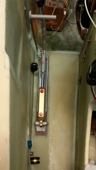
Here’s the alignment after I put some slight pressure on F-7.75 to the right for about 5 seconds. [Note: I realize that the center hole in the F-7.75 bulkhead is off center. A long time ago I had an original idea of bringing the point of the nose down a tad and since the heated pitot requires a significantly larger access hole anyway, I drilled it for a little R&D. On this install I turned the bulkhead 90° which greatly exaggerated the hole’s original down offset into the present offset to the right . . . in case you were wondering.]
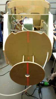
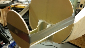
I then mounted the aft BC1 edges to Napster using 5-min epoxy. This pic was after about 20 minutes of me applying pressure to the BC1s for a few minutes so that they would set correctly, then checking the alignment with the laser, then re-applying pressure for a few minutes, and also tweaking the nose a hair to the right. Rinse & repeat.
I spent another 45 minutes or so ensuring that the F-7.75 & BC1 arms were attached well, and aligned correctIy, interspersed by collecting and cutting scrap BID pieces to make up 4 BID corner tapes to finalize the installation of the F-7.75 bulkhead. I whipped up some epoxy with fast hardener and of course prepregged the corner BID tapes.
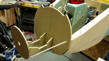
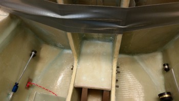
I laid up the corner BID tapes after applying flox fillets in the corners between the aft edge of each BC1 and the front face of Napster.
Here’s a shot after I pulled the prepreg plastic.

I then peel plied each corner tape layup.
As I was working the layup above, I would do a task or two (collect glass) then check the alignment, correct just a hair, then go back & do another task (cut glass) and then recheck the alignment to ensure it was maintaining at center. It had a natural tendency to pull left, so I would overcorrect to the right and if I stood there long enough, I could slowly see it go back to the left.
To ensure it didn’t move on me I taped it up with duct tape. However, I’m still going to do one final double check after I publish this blog post to ensure it’s still aligned properly.
Before I called it quits for the evening and headed upstairs, I pulled the peel ply from the nearly completely cured upper draft plate. That layup is looking as good as it should (it will get hidden by the F4.1 plate, so I’m not really worried about aesthetics).
Tomorrow I’ll clean up the BC1/F-7.75 corner BID tape layups and then start work on cutting & shaping the foam pieces for the remainder of the nose.