
Well, I stated yesterday that I was planning on working on the taxi light actuator extend & retract system . . . that didn’t happen. Today I focused on working to finish up the new nose gear system wiring.
I continued from where I left off last night and started by tying in the P2 connector to the mix. The P2 connector resides at the right midpoint mounting bracket on the NG30 cover, and was the original connect point of Jack W’s AEX unit. Now it has zero connections for the AEX function and is merely a break point for the wiring harness for making the removal of the NG30 cover EZ with just P2’s removal, and P0 on the RCU box. Besides an E-Bus fed power wire to the up/down limit switches, and an RCU box ground, the remainder of the P2 wires all deal with either LED indication of gear up/down transit, or AG6 warning annunciation for gear up and down.
I started by terminating the wires coming out of P1 into P2, installed the wires and closed up the A-side of the P2 connector with a cable clamp. I then selected and terminated all the wires to the B-side P2 connector, and installed the cable clamp (center top of pic).
Also, as you can see I (prematurely) mounted the AEM D-Sub 15-pin back shell (chrome silver-looking connector).
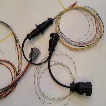
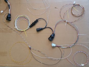
I moved the pic below up for comparison to the one above. As per Marc Z’s plan, I needed to solder a 560 Ohm resistor in series for the Laser Altimeter but forgot while I was building the aft side wiring harness for it. No big issue, sez me, I’ll just solder it in so it’s nice and tucked away inside the AEM 15-pin D-sub back shell (ID: Connector J9). Well, you got it… I forgot again! So I disassembled the back shell and spent a good half hour soldering one tiny 560 Ohm resistor in place. I insured I had heat shrink on the wire before I did my final solder, so was able to get a nice solid heat shrink piece in place over the soldered-in-place resistor & junctions. I stuffed all the wires back into the AEM D-Sub back shell, closed ‘er up and was back on track.
In addition to soldering the resistor into place on the AEM J9 side B connector, I also terminated every wire that came out of this connector. Six of 15 wires out of this D-Sub connector go to the RCU P0 connector, so I terminated those and plugged them into P0.
I also added another connector player into the mix at this point since this whole system is obviously controlled by the throttle mounted gear up/down switch. This meant running, terminating and mounting the gear up/down switch wires into the Throttle handle P4 connector (black & white twisted pair to upper left corner in pic below).
After the first round of wiring on the new nose gear system above, with its subsequent & requisite diagram updates, I touched up the aft NG30 cover with just a couple dabs of metal glaze and gave it another good epoxy wiping to eliminate some more pin holes that popped up. As you can see, I also slathered up the tool box lid to hopefully remove the minor surface irregularities that have been plaguing me in trying to get this one small part painted!
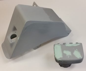
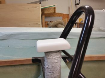
In addition, although taken quite a number of hours after I applied 3 coats of off-white primer, here’s a shot of the GNS480 GPS antenna cover that will sit atop my headrest. Since I had to go to town on it to remove the thick layers of my boat paint trial application, it too will need some TLC to smooth out the finish on it as well. Regardless, the color you see below will pretty much be the final color for this piece.
Tomorrow I’ll round up all the correct color/size of wire to cut, terminate, and mount it into the RCU P0 connector. This will finish up the wiring harness for the new nose gear. I’ll also continue finishing the nose components (and the GPS antenna cover). Finally, I do hope to sneak in some work on the taxi light actuator extend & retract system configuration. Regardless, although it seems like it’s baby steps on a bunch of nit-noy stuff, I am getting closer –inch-by-inch– to knocking out my self-imposed to-do list before getting back to the “main” build.