
I started off today by sanding down the top of the tool box lid with a straight sanding board with 80 grit on it. I took it down until it was level and then hit the top & sides a bit more lightly with 180 grit. I then washed it up & prepped it for a reapplication of high build primer.
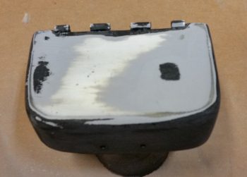
I tossed around the idea of just going back in with paint, but it’s going to need a couple of rounds of TLC for the surface to be ready for paint. That being said, I just hit it with one medium coat and called it good.
I then spent over 1.5 hours on prepping the aft NG30 cover for final primer. The top left forward corner and lower left edge where it meets the NG30 plate were both a bit shallow, so I added in some glazing putty to fill it in. I use the same stuff I did when I was building my custom motorcycle: Evercoat’s Metal Glaze. It works like a dream… mixes fast and creamy, and fills very smoothly. It also sands great as well.
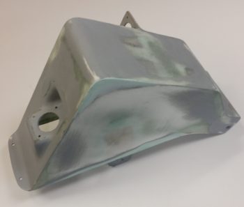
I filled one depression on the right side of the cover, and the upper forward corner area on the right as well.
After sanding down the filler and blending it in, I then hit the aft NG30 coat with 2 more coats of primer.
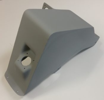
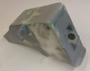
If you look closely, you can see the bleed through of the filler to the surface. I’ll lightly sand the cover one more time, then most likely hit just these areas again with primer before final paint. It may seem like I’m being overly fussy, but just like in composites, the prep in painting is really what takes the longest. The final few coats of base coat (or final here) is the culmination of a lot of prep. I just want to get this finish dialed into an acceptable level (yes, it doesn’t help that I’ve done body work & painting before… in that I’m sure it makes me a bit more picky) so every time I look at it I don’t get a gnawing feeling that I left a half hour more work on the table to clear up a minor, yet glaring, imperfection.
I was going to use a white primer on both the NG30 covers, then simply clear coat them. However, the primer I picked up was just not bright enough white for me to go on as the final color. So while I was out I picked up some actual paint (vs primer) and will just go with that, like I did on the tool box.
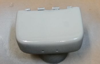
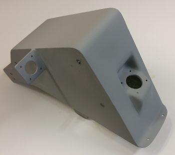
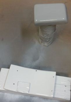
I then sanded down the boat paint trial application off the GPS antenna cover that will crown my headrest, and also prepped the forward NG30 cover. I hit the GPS antenna cover with a couple rounds of primer while I final coated the forward NG30 cover with 2 coats of gloss white. I’m using gloss on a few of the internal nose components (the GPS antenna cover will not get gloss) just to make them pop a bit and stand out from the otherwise mass of matt finish that will be the main finish in the nose compartment and cockpit.
I was doing some research online about Rustoleum paint, and ran across something that made sense to me: since rattle can paint & primer doesn’t incorporate a reducer (like auto paint), it takes a few days to really off-gas and cure to a good point. I noticed this dynamic on the lower tool box, thus I figured I would leave this stuff alone for at least 24-30 hours before working on it again.
I set my sights back on my new nose gear wiring since the diagram was full of chicken scratches, notes, marker highlights, etc. One task that really needed to get completed was the deconfliction of P1 connector pinouts. You see, when I rewickered Jack’s original Molex connector and rewired the nose gear system through an AMP CPC connector for P1, I changed the pinout numbers. When Marc Zeitlin released his wiring diagram, he logically used Jack’s original pinout numbers. When I redrew the new wiring diagram, and merged Jack’s and Marc’s systems, I used the original connector pinout numbers instead of mine. This required me to go back tonight and re-label the P1 connector on the diagram with my pinout numbers vs Jacks, since I’m not going to pull the gear actuator side (B side) of the P1 connector apart to re-terminate it. It also required me to pull and re-pin the P1 connector (A side) terminals using the correct numbers.
However, I did build and add a jumper wire to pins 2 & 8 to allow me to use the P1 connector for routing of a ground wire coming out of the RCU. Doing this simply cleaned up the wire bundle and actually streamlined the wire routing.
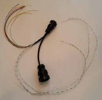
I then soldered two 22AWG wires close to the terminal pin on each of the actuator motor power wires on the P1-A connector for the gear up & down transit LED indicators. After I soldered the wires in place I heat shrank the soldered joints to secure the wires & junction. I then finalized the A side of the P1 AMP CPC connector, covered the wires that traverse to the RCU’s P0 connector with a mesh cover, cut the remaining wires that will terminate into the P2 connector (upper left in pic below) to length and then snapped a shot of it all.
Along with the main nose gear wiring diagram, I also updated the P0, P1 and J9 connector pinout diagram pages. Tomorrow I plan on working on the taxi light actuator extend & retract mechanism to get that knocked out.