
In the movie “Apollo 13,” Gary Sinise’s character –who was an astronaut left on earth and didn’t go on the mission– is trying to find an optimal way to save as much electrical power as possible for his buddies in their damaged spaceship…getting slung around the moon and heading back to earth. He tells another character that efficiency they’re looking for can be obtained as long as they get the correct sequence…. and that, my friends, is exactly what I’m trying to do! Get the right sequencing down in order to be as quick and efficient as possible on this build in the long run.
You may have noted that it seems like I’m all over the map on this build, and I may be a bit. But what I’m really trying to do is to get all the prerequisites to certain tasks completed so that when the original task is complete, there’s no rework or lost optimization. That methodology of course entails quite a few rabbit holes that can take hours, days or even a week or so to complete as a prerequisite task for the original task. The original task of course is still there, waiting to be completed, and it will be . . . after the prerequisite tasks are all finished. I hope that was all clear as mud!
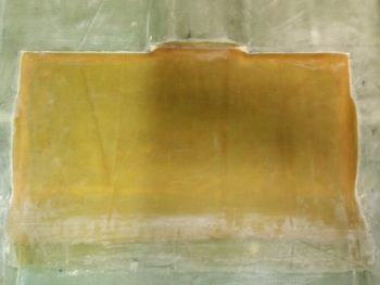
I started off today checking out what was an extremely wet, epoxy-laden layup on the interior side of the fuel sump front wall.
I pulled the peel ply and trimmed the edges. Not too bad. I’ll probably leave the epoxy ridges unless they present a problem.
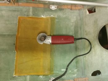
I started off trimming the fuel sump floor layup with my razor knife for a while, then grabbed my “Fein” saw to trim the remaining overhanging glass.
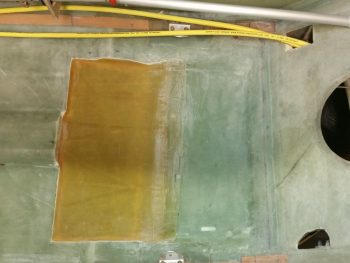
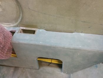
Although it doesn’t look that much different from above, I trimmed all the excess glass away. As you can see, I also took a few minutes to run the big yellow power cables back to the hellhole. I need these power cables ran so I can verify the size and shape of the front right side sump tank wall mount, since the front sump tank wall is essentially a bulkhead that goes from one sidewall to the other.
I then needed to figure out my spacing and configuration under the right front armrest for my fuel lines and big power cables, as well as the other smaller wire bundle as well. To do that, well, guess what? I needed to mount the map pocket in its position.
So I worked for about a half hour shaping and dialing in the exact spot it would get mounted. I then transferred the opening shape over to the right armrest, and trimmed a notch in it the size & shape of the map pocket.
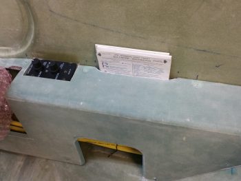
Here’s a test fit and a shot at how the map pocket looks with the intercom installed.
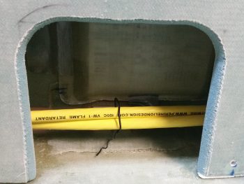
And a pic of the lower map pocket and the big power wires heading for the firewall.
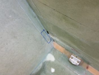
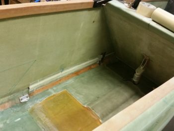
Although I hadn’t finished with the right side forward sump wall edge configuration, I wanted to get some glass curing, so I worked on the left side a bit. The pic below shows a small opening in a slight depression in the side wall at the lower left edge of the pilot’s seat back. This opening will carry 3-4 antenna cables to the aft fuselage and eventually the wings. The blue rectangle is where the heating duct will come forward from the oil heat exchange behind the pilot’s seat on the left sidewall. [The oil heat system is another system that I pretty much just finalized the configuration for.] So before the fuel sump front wall goes up, there needs to be some accounting of the items that will traverse across the left sidewall edge of the front fuel sump wall.
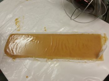
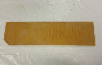
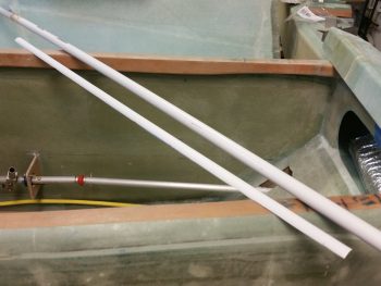
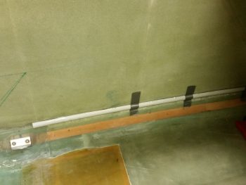
Additionally, the heating duct that I will be putting in actually needs to be run right over the channel that the antenna cables were meant to go. Thus, to protect the antenna cables, make them removable, and still keep them in the same place, I cut out about a third of a side of one of my German “PVC” pipes. These things are really thin, but fairly strong. I weighed the piece that I used and it came out 0.92 oz. Not bad.
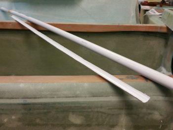
Here’s a shot of the other side of the piece of pipe that I’ll be using. I cut it length ways using a utility knife (that’s how thin it is), so it’s not a perfect cut.
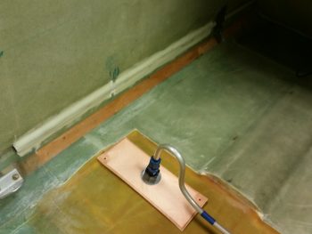
After a fair amount of sanding to expand the opening a bit on the lower left side pilot’s seat, I was then able to slide just a peek of the antenna cable channel cover into the opening. I wanted just enough poking out to feed the antenna cables through.
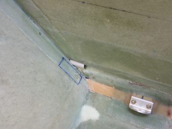
I taped the antenna cable channel cover to the side wall groove in the GIB area, and then 5 min glued it in place.
Using dry micro, I then covered the depression that ran the length of each side of the antenna cable channel cover (above & below it), which is caused by essentially having a segment of smaller circle sitting inside the segment of a bigger circle.
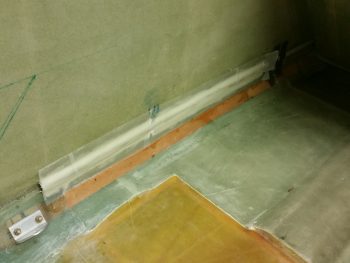
I then laid up 1 ply of BID in two separate pieces onto the antenna cable channel cover. Installing & glassing this antenna cable channel will allow me to account for it when I mount the fuel sump front wall.
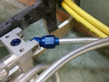
I then started back in on the right side cockpit. I flared the tubing for an AN fuel line fitting, shaped the engine feed fuel line and ran it off off the fuel boost pump. I then did the same thing for the left sump tank feed line running it aft from the fuel selector valve.
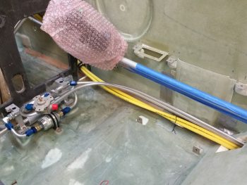
Here’s a closeup of the fuel selector valve with the left fuel sump feed line freshly attached.
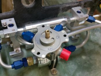
I swapped out the clockable 90° AN fitting for a 45° fitting on the fuel boost pump to get a better exit angle to the sidewall and then aft.
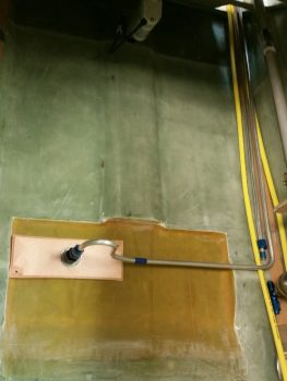
I then spent some time bending and shaping the left sump tank line to get it into place and flared with AN fittings to allow it to connect to the Holley Hyrdamat fuel intake.
In looking at these pics I realized that I should have done a zig or zag with my left fuel sump line to give a little elbow room for the right side fuel sump tank Hydramat. I’m not too worried since I’m sure I can finagle some space somewhere!
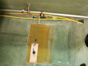
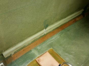
Here’s a shot of the left fuel sump feed line connected to the Holley Hydramat. Also, you can see the cured antenna cable channel layup in the back as well.
Here’s a closer shot of the glassed antenna cable channel. I still have maybe a foot left to glass on the forward side, but I wanted to get the lion’s share of this laid up tonight. With the really dry micro and the lightweight conduit piece, I’d be surprised if this whole antenna cable channel weighs more than a couple of ounces.
Tomorrow I’ll continue figuring out –and laying out– those components that affect the configuration of each side of the fuel sump front wall. Once those items are complete, I can then best design the openings on each side of the fuel sump front wall/bulkhead, and then glass in the front fuel sump wall.