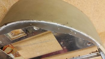
My plan was to work about half a day on the headrest and then get it glassed into the fuselage and move on . . . that did not happen.
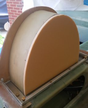
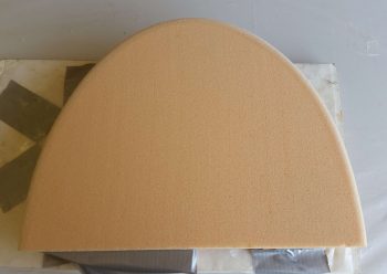
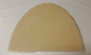
I started off by cutting out the front face cover of the headrest out of 3/8″ thick PVC foam and then carefully sanding it so that the cover’s edge was just slightly smaller than the headrest’s, to allow for the thickness of the glass.
I then rounded the edges of the headrest front face cover piece.
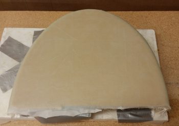
I then glassed the front headrest cover piece with 1 ply of UNI with the fibers running horizontally and then 1 ply of BID on top of that. I will say I finagled with the edge for a time to get the glass to lay down as nice as possible around the edge. I peel plied the cover layup and let it cure. I will also note that because of my aforementioned aligning issue with the right engine mount extrusion, I had to add a small strip of foam on the bottom edge of the right side.
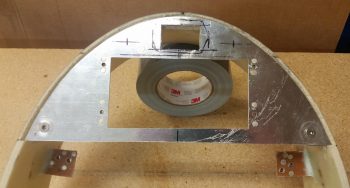
Barely visible in the pic below is an added set of #8 nutplates on the upper angled aluminum crossbar mount tabs sticking out from the sidewalls. I’ll point this later on, but these are for a pair of #8 CS screws –one each side– that actually hold the crossbar in place, since the bigger #10 screws that previously held on the crossbar did double duty and also held the SD-8 heat sink mount and Electroair controller in place, respectively. If I removed either of the #10 screws to remove either component, I was unhinging either side’s mounting point of the crossbar. These #8 CS screws allow the mounting crossbar to be held in place regardless if components are installed or not.
I then got to work on the headrest top plate. I drilled, counter sunk and riveted in the nutplate assemblies for the lower top plate mounting screws. I had to go one size up than I had planned, to #10 screws, since I am rapidly depleting my nutplate bench stock!
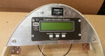
Also, I measured, marked and cut out a rectangular window above the EIS4000 cutout for the Hobbs meter to peak through.
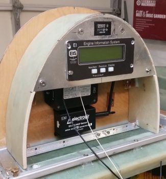
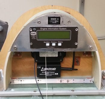
Here’s a quick mockup with the Hobbs meter now visible and the EIS4000 set in place. Note that the EIS4000 screw holes have been countersunk so that the screws will sit as flush as possible. Also note that I drilled and countersunk the top #10 screws for the top plate, although the nutplate assemblies have not been floxed into place yet.
I then set the mocked up top plate & headrest into place on the fuselage. I have to say I’m very pleased with how the headrest is coming along, although it is taking a bit of time to complete.
When the GIB headrest is glassed into place on the fuselage, I want it to be as complete as possible with all components, no matter how minor, small or “important” to be accounted for and set in position. Thus, I had been mulling over where exactly to place the very lightweight cooling fan thermal control unit in this matrix inside the headrest.
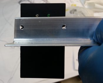
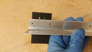
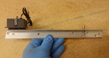
I decided that it would go on the right side, mounted to the upper mounting crossbar, adjacent to the interior right headrest sidewall. I decided to use velcro to secure it in place, but wanted something a little bit more secure as well. So I drilled 2 small holes in the top of the angled aluminum mounting crossbar and then notched the flange on the cooling fan control unit to match the holes. This way I can use a piece of cable lace to positively secure the cooling fan control unit in place in addition to the velcro.
Here’s another shot of the cooling fan control unit held in place with velcro with the 2 wire lace holes visible. Note that the operating LED indicators are located on the forward side of the mounting crossbar, so that they will be visible with the headrest front cover removed.
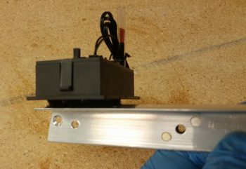
This shot shows how it will look when mounted inside the headrest.
And just a final closeup of the cooling fan control unit mounted in place with velcro.
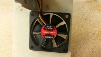
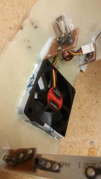
With the cooling fan control unit mounting squared away, it was time to turn my sights on the fans themselves. I have one 60mm cooling fan that blows external air into the headrest, and is positioned –not coincidentally– right next to the SD-8 voltage regulator. It also is positioned so that it blows cooler air right down the row of bottom mounted components in the headrest: SD-8 voltage regulator, SD-8 bridge rectifier (mounted on a heat sink) and the Electroair EI controller, all which have cooling fins to facilitate cooling during normal operations.
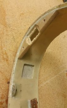
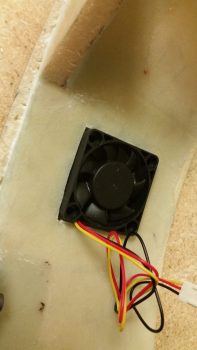
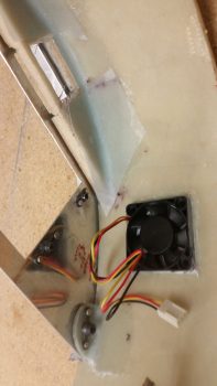
I then have a 40mm exhaust fan to remove all the warmer air from the headrest housing. It’s positioned on the high side (warm air rises) at about the 10 O’clock position when looking straight at the front of the headrest. Since I did not want to have the air flowing through thick cutouts into the headrest sidewall, I decided to simply place the exhaust fan as flush as possible with the external glass of the headrest. To do this I clearly had to remove the internal sidewall glass and the foam in between, as I did below.
This allowed the exhaust fan to sit right against the external headrest glass, and reduced the footprint of the exhaust fan considerably by embedding it in the sidewall.
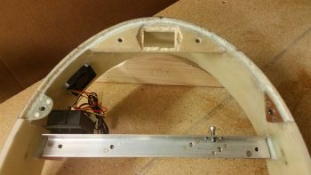
This pic actually shows quite a bit. You can see the cooling fan controller unit mounted in place with velcro atop the mounting crossbar. It also shows the position of the embedded exhaust fan. If you look at the glassed in foam reinforcement piece at the top of the headrest arch, you’ll see the foam and glass dug out to allow for the Hobbs meter to be set down below the surface of the top plate, slightly embedded as well. Finally, if you look closely you can see the #8 CS screws in place on each end of the angled aluminum mounting crossbar, securing it in place.
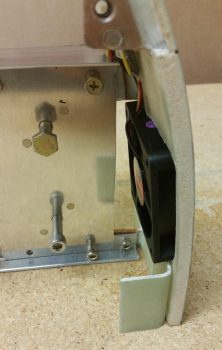
I honestly hadn’t planned on embedding the larger 60mm intake cooling fan but since I needed clearance for the headrest cover mounting CAMLOC tab just below the fan, it required me to move the fan up as far as possible. With the fan surface mounted on the inside headrest sidewall, I couldn’t move the fan up since the SD-8 heat sink mount interfered with any upward positioning of the fan. The only way that I could keep the fan in its optimized position for cooling the lower air-cooled components was to embed it in the sidewall as well, which allowed me to position it farther up and still provide clearance with both the SD-8 heat sink mount and the front cover CAMLOC mounting tab (shown set in position).
Yet another view of the embedded intake cooling fan.
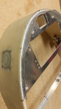
And the notched sidewall glass for the embedded intake cooling fan.
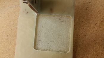 I then glassed in a square piece of BID that made up the “floor” of the cooling fan notches, and then added another piece of glass that actually covered the micro’d recesses I created on the sides of each notched hole. I figured this would added a little strength back into the headrest structure at minimal weight. However, this created a potential fitting issue if the glass on each side decided to be a bit thicker than required. Also, to help keep the glass along the narrow edge of the sides of the notched holes, I simply taped up the fans to protect them and then inserted them into place to keep the glass positioned correctly.
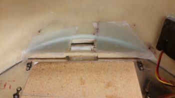
In the pic of the exhaust fan above, and below, are 1-ply BID reinforcement layups that I glassed in on the back side of the top plate reinforcement structure. With the big hole that I dug out on the front side for embedding the Hobbs meter, I decided to add a bit more structural strength on the back side. I can’t really add any glass on the front side since it would push the top plate out of position.
During the placement, sanding and alignment of the top plate, the interfacing edge of the headrest structure –being just foam– has been reduced to a narrow strip. To get the foam edge back to its original thickness, provide a more seamless edge with the top plate, and to a degree finish the edge for paint, I decided to tape the edge of the top plate and then lay in a small bead of flocro along the headrest edge adjacent to the top plate edge.
I then pulled the peel ply and razor trimmed the glass along the aft edge of the headrest front cover. I will need to do some clean up sanding and aggressively sand along the edges to get a few bumps and slight irregularities knocked down in place.
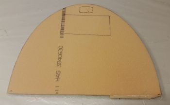
Here’s the aft side of the GIB headrest face cover plate. Note that I will make some depressions in the aft side face before I glass it to ensure clearances with the internal components of the headrest, specifically the buttons on the front of the EIS4000 unit… which currently sit recessed below an imaginary line drawn across the face of the headrest’s front edges, but just barely.
So, I’m hoping that TOMORROW will be my half day on the GIB headrest structure build, and then I can get it glassed into the fuselage and move on with the nose and canopy build!

