
Today was a day of lessons for the ‘ol Airdog here. First off, my buddy Dave B. asked me a question on this website regarding the use of an ANL type fuse link for the SD-8 backup alternator, and if I did use one was it located aft or in the nose? Wow, ok… probably a question I should have asked myself and a big oversight on my part.
As I see it (after Dave’s prompting) the logic flows like this: I just moved the ANL40 fuse link on the B-Lead aft because the antagonist in my view was the main 40A alternator. I again based this off of Bob’s statement that the fuse should be closest to the offending power source. Ok, now the SD-8 backup alternator is in the back as well, but its 30A fuse –as spelled out specifically in the Z-13/8 system architecture– must be located within 6″ of the master contactor (in the nose). But why? The key I discovered is identifying the potential antagonistic power source, which I had done incorrectly.
I posted this question on the AeroElectric Connection forum and almost immediately got a response: the alternators are not the main point of concern since if the wire leads from them are rated at the max current they can produce, then the wire will be safe. However, the battery is a source of potentially hundreds of errant amps hitting the wire if it decides to go a little haywire.
Thus, I had picked the wrong villain, and as Sun Tsu says, “Know your enemy.” I did not. This of course meant that my action to move the ANL40 fuse link aft was all for naught, and moreover, incorrect. Lesson learned. So, my latest diagram should be depicted as such:
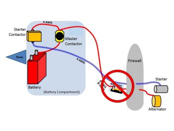
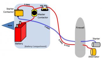
And my new configuration for the ANL40 is nothing more than my previous CORRECT depiction, shown here. Ahh, the circle of life…. ha! I haven’t yet moved the ANL40 fuse link, but I will be leaving the mounting pad on the face of the firewall in the hell hole until I know for certain that nothing else needs to get mounted in there.
In a subsequent discussion Dave and I discussed alternators going haywire, and as a point of note I’ll state that alternators such as the ones B&C sells have built-in OverVoltage protection to guard against runaway alternator current causing damage.
Moving on.
I had a lengthy discussion this afternoon with Mike Beasley, who many of you may know from his awesome website. (Admittedly, there’s not a lot of verbiage on his site, but for the fellow Long-EZ builder the pictures on his website are a treasure trove of information).
Lesson #2 of the day for me was Mike providing me with the finer points of how he constructed his canopy. We spoke a bit on a few other topics such as throttle and mixture cables, but the near 2-hour long conversation focused primarily on the canopy and nose build. I am very thankful for the time that fellow Canardians take to collaborate on such tasks as this, and it really does make the build so much more manageable (and enjoyable).
While I discussed the canopy and nose build with Mike, the FedEx guy delivered my last (hopefully) round of fittings that I ordered from Summit Racing. Again, my first choice for connecting the hose coming down from the fuel distribution spider atop the engine to the -4 AN 90° fitting on top of the fuel injection servo was the 150° hose end fitting. And as I mentioned before, my backup was a 90° hose end fitting if the 150° hose end didn’t work out.
Quite nicely, however, the 150° hose end fitting worked like a champ!
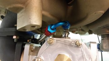
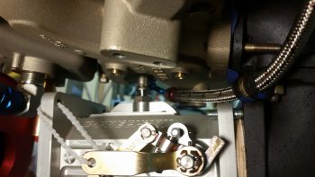
For this fuel line, I also employed and test fitted an Adel clamp secured by the front left corner bolt where the induction air intake elbows mate together. I think this Adel clamp position will work nicely to secure the -4 hose going to the fuel distribution spider from the top-mounted fitting on the fuel injection servo.
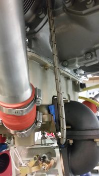
Here’s a bit closer view of the -4 fuel line feed to the fuel distribution spider from the fuel injection servo.
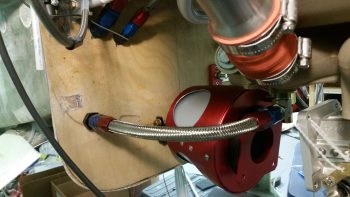
I then took a while to figure out and dial in the position and angle of my oil sump oil heat feed line that exits out of the bottom of the oil sump via a 90° steel fitting (that I calculated a 4.4″ tall standpipe will get welded to) to a firewall pass-thru fitting. I had some angled hose end fittings on hand, but decided that to keep a nice constant curve around the RAM air box that I’d use straight hose end fittings.
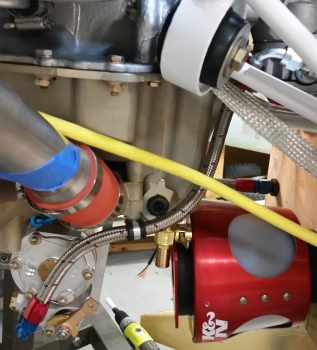
I then spent a couple of hours assessing and dialing-in the flow and Adel clamp attach point for the final piece of hosing to complete the fuel line from the fuel intakes in the main strake-located fuel tanks to the cylinder fuel injector nozzles: the -6 hose from the fuel pump to the fuel injection servo.
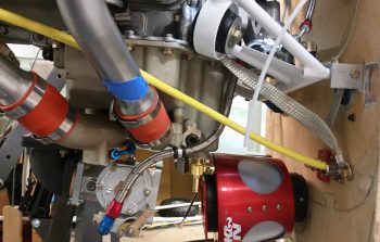
At the fuel pump side I actually entertained the idea of cutting part of the flat flange insert at the corner of the engine mount in order to have the fuel pump out hose end fitting face outboard of the engine mount tube. But, laying below the engine looking straight up at it, I realized that more of the hose end fitting was showing on the inboard side than the outboard side, meaning that I could get a more down angle of the hose end fitting by leaving it inboard. So, no drilling or cutting of the engine mount flange took place.
On the fuel injection servo side, I had planned on actually running the hose aft and looping it in from the aft side to arrive at the fuel injection inlet fitting at a 0-45° angle. But then after looking at and assessing the travel of the mixture lever on the fuel injection servo, I decided to simply bring the fuel line down from the top from a slight forward-to-aft angle.
So here it is: the final fuel line piece for this entire aircraft. Yes, of course the fuel VENT lines will still need to be run, but this does it for the actual fuel lines.
Tomorrow I’ll prep for the removal of the engine since I have the lion’s share of data that I need from having the engine mounted. Moreover, I’ll most likely clean up the shop and take some pics of engine mounted on the fuselage before removing it.