
Today I started off working for a couple of hours updating 5 electrical diagrams:
- A. Switches, Breakers & Panel Lights
- .99 Grounding Busses
- 4. Electrical System Components Map
- 10. Fuel System
- 11. Cockpit Lighting
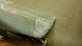
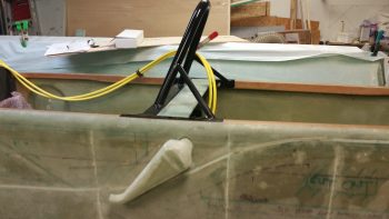
I then spent a couple of hours on the left GIB armrest. First off I DA sanded down the somewhat grotesque layup edges that where created when I added the top and front extension pieces you can see in the pic below. Unfortunately, being in a rush to make up for some lost time on personal stuff today, I had one fuzzy pic and simply didn’t take any others. I know: for shame! The end result is not only did I radius the front edge and glass it with a ply of BID, but I also filled in some holes with micro in a few different areas on the armrest.
Moreover, I cut a square notch on the very top inboard INSIDE corner that will mate up to the GIB PTT button housing that will be incorporated into the sidewall bracket that will also house the GIB headset jacks. In addition to the top curve, I also glassed the inside surface of the PTT button bracket notch I made with 1 ply of BID. Of course all the layups got peel plied. I’ll get a pic of all the interior layups tomorrow.
I then set my sights on getting the ram air inlet, expansion chamber and transition piece installed on the (current) exterior side of the fuselage. I double checked my dimensions, moved my initial drill point forward and down just a hair, and then drilled it with a small pilot bit.
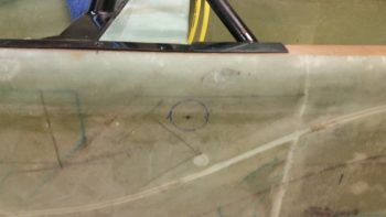
And Bingo! Center of mass on the interior marked hole.
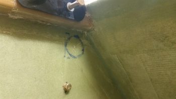
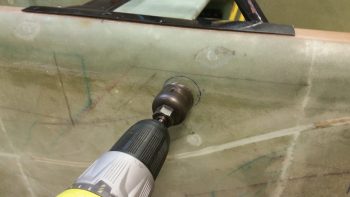
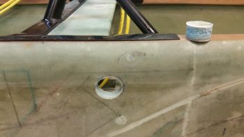
I double checked the overall configuration of how the ram air inlet, expansion chamber and transition piece would mount on the exterior sidewall (which will be inside the strake baggage compartment when the plane is finished). I then loaded up a 1-1/2″ hole saw bit into my drill and literally pulled the trigger!
Here’s the initial 1-1/2″ diameter hole into the fuselage sidewall, obviously just aft of the pilot seat and just under the left longeron. You can see the drilled out plug sitting atop the longeron.
Here’s a couple of shots of my test fitting the ram air inlet, expansion chamber and transition piece into place. The transition tube on this component is 1.5″ ID, which means I had to widen the hole out a bit for this piece to fit into place. Also, I had to radius the outer perimeter of the hole a bit from around the 5 to 10 O’ Clock position for this thing to mount close enough to the sidewall.
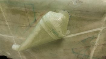
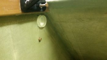
I intentionally glassed the 1.5″ ID air transition tube of the ram air inlet, expansion chamber and transition piece a little long so that it would definitely clear the inside surface of the fuselage sidewall. However, the excess, overhanging tube edge will be cut down so that the transition tube edge is flush with the interior surface of the sidewall, since the air will immediately flow into the heating and fresh air ductwork at this point.
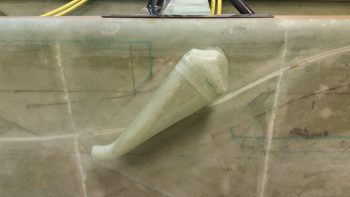
You know me, the peel ply king, and the one time I thought I could get away with not doing it, I ended up needing to sand this sucker down… well, in the end not all of it, but a good portion of it! I call this picture: The Mummy in Repose …. haha!
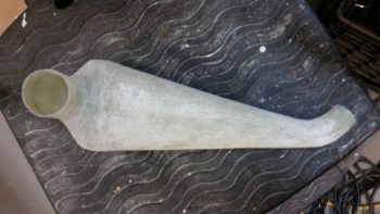
Now, I need to research just how far away from the outer skin the intake needs to be mounted, so the ram air inlet, expansion chamber and transition piece floxing-in & glassing is on hold until I finalize these installation specs. If anyone out there is smart on this, by all means send me a note! Here it is one last time, mocked up after I sanded it down.
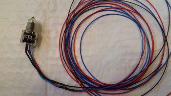
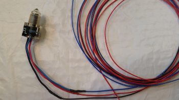
After all the excitement with the ram air inlet, expansion chamber and transition piece, I decided to do something more my speed: heat shrink! I finally got around to cutting the heat shrink tubing for the left & right sump tanks low fuel level sensor wires and heat shrunk them in place.
In my short term quest to finalize the GIB area components install, tomorrow my main effort will be to get the left GIB armrest forward bracket mold made up so I can glass it up. Over the next few days I want to get the left GIB armrest bracket completed and have a good amount of the oil heat & fresh air ducting figured out & built.