
I think in general it takes stressing the electrical system operationally to find various areas of optimization. Obviously I’m not saying my airplane is at a fully operational state to allow for a real world stress test, but as I get nearer to that goal, and a major of my systems are up and running, there’s simply fewer “stones” to overturn in finding potential issues and fine tuning the electrical system. Through collaboration with other builders and my own armchair flying, I have discovered some key areas of optimization in my electrical system architecture over the last couple of weeks.
Just in the past two weeks –to kick off 2018– was the great “Starter Contactor Relocation” fiasco…. where I think I actually ended up with a much better starting system architecture than what I started with.
Next, in discussing details of Dave Berenholtz’ electrical system with him, it made me go back and take a look at some details of my own system, really in a manner more of “checking something out” just to answer a question he asked. In assessing my alternator capacities and 3 layered electrical system (main alternator, E-Bus/SD-8 backup, and IBBS) I realized a change that I had made when installing the IBBS into the system –based on some info that Bob from TCW Tech and I discussed at the time– may have been a good thing on the face of it, but a deeper issue was presenting itself.
This made me take an in-depth look at my SD-8, E-Bus and IBBS architecture. I actually stumbled across something that made me take a second look at how I had modified it from my very original install. Unfortunately, I didn’t do my due diligence in truly assessing the operational impact/flow in an emergency scenario where I would be required to take the main alternator offline and employ only the SD-8 powered E-Bus. By having the IBBS on my main bus it essentially made it so I had no pass-thru capability (IBBS will both drive components from connected bus power or provide its own backup battery power) so in an E-Bus only scenario I would be driving single point connected items straight to IBBS power that is my last resort (layer 3: IBBS power)…. in short, meaning only 45 min operating power for those items vs. letting them happily draw power from the SD-8/E-Bus for the duration of the flight.
I called Bob at TCW and we worked through my issue. The only viable fix to allow these components that are hooked up to ship’s power ONLY through the IBBS’s pass-thru connection (bus power) to draw power via either the pass-thru feature (bus power/layer 2) or IBBS power (layer 3) was that I needed to move the IBBS off the main bus and put it on the E-Bus. This allowed those IBBS components hooked up to bus power via the IBBS pass-thru feature to then be powered off the SD-8 if I needed to go to layer 2 power, and then eventually to layer 3, IBBS power (~45 min off the IBBS internal battery), as a very last resort.
However, I would then need to take one more step to make it so one of the IBBS’s charging power leads gets disconnected to disable the IBBS from attempting to recharge (2.5A) off the E-Bus when solely on SD-8/E-bus power. Bob from TCW recommended that I run the IBBS recharge lead through a 5A circuit breaker on the panel, but instead I’m going to employ a relay that will trip automatically once I select the SD-8 as my power source. Then, when/if the E-bus only scenario ever plays out, in the heat of having just dealt with my main alternator going offline (meaning my having just been subject to haywire readings and troubleshooting to decipher what’s really going on before then deciding to take my main alternator offline… this all of course equals STRESS!) and bringing my SD-8 online as the new primary alternator (main bus offline/E-Bus only power), I don’t have to try to remember to pull that circuit breaker (yes, it would be on the checklist, but I like to automate if/where I can!). Plus a relay adds considerably less weight and puts that weight in the nose vs more weight on my panel (also, to be honest, a heck of lot cheaper as well!).
All of the above was not without penalty or effort to be certain! It required a considerable reconfiguration of all of my 3 power bus (main, E-Bus, battery) connections, where I ended up playing musical chairs primarily with my IBBS and Electroair EI power connections. The big-picture net result was that I moved the IBBS from the main power bus to the E-Bus, and both Electroair power connections from the E-Bus to the battery bus, with the resulting paper trail that ensued. Of course, not only did I update my power buss tracking sheet, but also as I detail below, every electrical diagram where this info was present.
I then performed an entire review of ALL my wiring diagrams as I updated this latest IBBS /SD-8 circuit change (I added that relay to auto-shutoff the IBBS charging circuit when I go to SD-8 only power on the isolated E-Bus) and all the other little inherent nitnoy changes (wire color, etc.) that I’ve made to make the diagrams match my actual wiring. The end result was updating and printing out 18 diagrams . . . and even then I had to go back through after I printed a few out and annotate some further changes! Finally, since I’m in engine install assessment mode, I also annotated all my firewall pass-thru points on my diagrams with either an “H” or an “L” in a big hex outline to depict whether they pass through at the high point or low point pass-thru (I’m thinking the current requirement is only for two firewall wire pass-thrus).
Moving on.
I’d also like to report something that is of minor note to be sure, but a to-do item checked off my list nonetheless: I purchased my fuel flow codes from GRT that allows me to integrate my FT-60 Red Cube fuel flow meter with the GRT EIS4000. This means that I have one minor non-GRT Hall Effect sensor to purchase to enable a more traditional battery charge/discharge ammeter (only with REAL #’s) at which point all my array of EIS/EFIS feeding sensors will be in hand/configured.
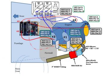
Looking at my firewall components wiring and component placement planning, I then took a bit of time to re-read Section IIL of the plans to glean any good info from it that I could regarding the eventual engine install (a reminder: it’s still below freezing here weather-wise, so I’m still in non-shop work mode). I was looking at this page (below) and started playing around a bit and ended up graying out all the components on the original firewall diagram that WILL NOT be on mine. BTW, to be clear there are no “replacement items” for those grayed out below, they are simply removed. The closest to a swap out you could say is the in/out oil lines for the oil heat system.
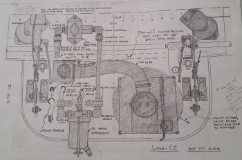
One point of note planning wise, is that I relocated the main electrical cable firewall pass-thrus from the lower left corner (looking forward) of the firewall to the lower right, a bit below where the aileron control tube exits the firewall. This location minimizes/straightens the cable run lengths and keeps my firewall ground, starter, alternator B-lead and F-lead all within about an area around 4″ in diameter.
Also, I understand this is a rather campy, convoluted looking slide below, but it’s essentially just one of my notes’ pages that gives me all the pertinent info I need represented visually. As you can see, essentially I’ve pretty much figured out all my wire runs (initial plan anyway) both in the engine compartment itself and through the firewall.
In prep for the engine coming home to my shop (soon I hope!), I’ve been slowly buying all the parts I need for my engine dehydrator ala Bill Allen’s FaceBook post where he provides details on how to construct one of these things for fairly cheap (see video below). Here are the components I’ve acquired thus far. I’m awaiting the humidity sensors (hygrometers) that I ordered and will purchase some desiccant soon as well. In addition, I also ordered 4 each cylinder dehydrator plugs from ACS. I figure between an active airflow dehydrator and the cylinder plugs, it should keep the engine internals quite dry enough to prevent galling or corrosion. Moreover, I don’t want to do a full on oil-soaked pickling of the engine since I really think it will only be unused for less than a year at the very most.
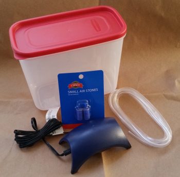
Bill Allen’s engine dehumidifier video:
In addition to my electrical system shenanigans above, I also created a new ground bus “G6” for just the D-Deck/Turtleback area. It will be a 9-pin D-Sub connector that is connected by two (2x) 18AWG wires that run from the Hell Hole’s G3 ground connector (pictured below). This will provide me one simple ground point to contend with in the GIB headrest/Turtleback area and will keep me from having to run a fair number of separate ground wires down to the hell hole.
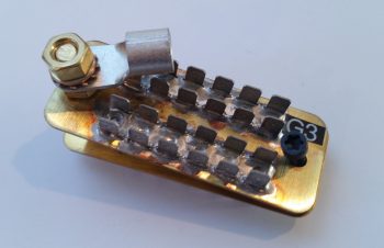
Moreover, I’m removing the firewall “forrest of tabs” ground connector on the firewall side and will use just the bolt since I have only two items on my engine that need ground wire connection points (Electroair coil and PMag). Below is the original B&C “forrest of tabs” firewall ground busses. The firewall ground bus identification is G2 while the Hell Hole ground bus identification is G3.
Here’s a shot showing the G2 firewall ground bus.
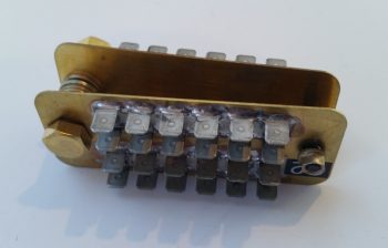
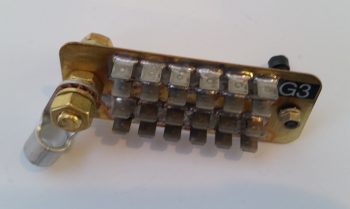
And the other side of this contraption, the G3 hell hole ground bus (with the terminal for the big yellow ground cable attached for inventory tracking).
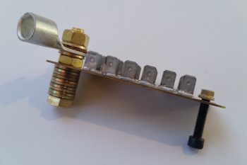
As I stated above, since I only have 2 firewall component ground wires to contend with, I’m not putting that busy looking monstrosity back on the firewall to simply take up weight and space when it’s not needed. Here’s how it will look on the firewall (ok, if my bird were doing a full afterburner climb like an F-15…. ha!)
And one last shot of the G2 firewall ground bolt (by itself now) and the remaining G3 hell hole “forrest of tabs” ground bus.
As I’ve mentioned quite a bit over the past month, it is still pretty darn cold here on the mid-Atlantic coast, so I continue to do all those tasks that I won’t want to expend the time to do when it’s warm… and good glassing weather. I’ve gone off on a few sideline electrical system design rabbit holes, but all for the greater good in my opinion. I’m hoping to spend a day early to mid next week to finish up my engine and bring it home. I’ll also continue to work to knock out these electrical system taskers up to late next week, which I will then again be heading down to NC for a long weekend visit.