
Before I get to the AEM box wiring, I’m going to cover a couple of other items first.
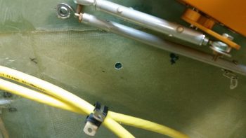
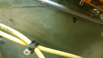
Today I identified another location to mount an Adel clamp hardpoint for my big battery power cables coming out of the nose. I marked and then drilled the hole for the hardpoint.
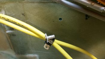
Here’s the same shot, but I added the threaded insert in the pic.
I whipped up some flox and mounted the threaded insert in the hole. I then clamped a board onto the threaded insert to keep it in place.
I grouped the pics in this post by topic, not chronologically, so I’m jumping ahead about 8 hours here to show the nearly completely cured flox. I cleaned up the flox that oozed out around the taped up washer.
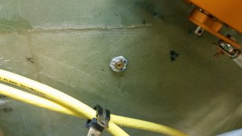
A couple of hours later I removed the bolt and popped off the washer. I cleaned up the flox, finishing up the install of this hardpoint.
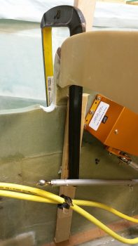
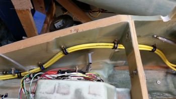
Here’s my progress so far on getting the big battery power cables routed out of the nose battery compartment –with clearance for my right rudder pedal– to my immediate goal: to the instrument panel.
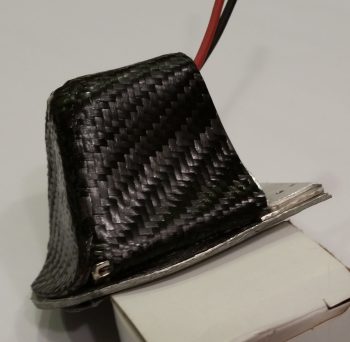
Moving on. I laid up the final carbon fiber ply on the right side of the taxi light cover. It took some tricky machinations to get it lined up at the CF intersections, but it all seemed to work out. To be clear, I did use a “trash” piece of CF here for this final ply.
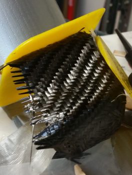
I checked it a bit later while the epoxy was still just a bit tacky, so I was able to mash down the edges/intersections CF.
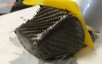
After the carbon fiber layup cured, I did a knife trim and quick cleanup.
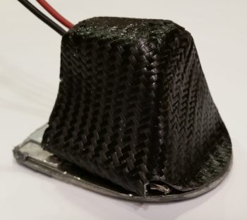
Here’s a shot of the left side. I need to still sand it down and hit it with one more application of epoxy. It’s still not going to win any beauty contests, but it looks a ton better than it did obviously when I first glassed it!
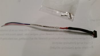
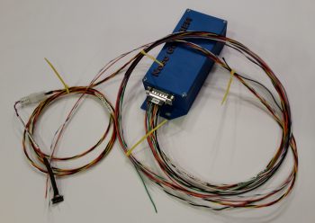
I then started building the wiring harness for the AEM box. My first task was to configure the wiring connector that came with the laser altimeter. There are a lot of extra wires that come on this connector harness, so I cut those to a usable length in case I need them later, then wrapped them up and heat shrunk wrapped it to the cable harness. I then terminated the 3 wires I’m using with mini-Molex sockets and mounted them into the mini-Molex connector.
I then spent a couple of hours building the wiring harness for the AEM box.
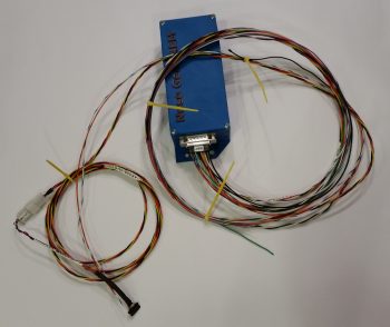
I measured out the required wiring lengths for most of the wires, and estimated the lengths on a few of the wire runs to the panel. I performed a continuity check on each wire as I terminated the D-Sub socket on it.
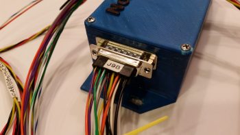
Here’s a closeup shot of the AEM box D-Sub 15-pin connector with all the terminated wires installed.
Tomorrow I’ll install the last big battery power cable Adel clamp hardpoint for my immediate goal of getting these cables’ routing locked down from the nose to the panel. I’ll also start working the pivot arm & bracket for the taxi light to provide an attach point for the taxi light deployment/retraction actuator.