
Since arriving back home from my latest NC/Virginia Beach trip I’ve been in a mad dash to finish up some of the tasks I started while on my journey.
One such task was to finish sketching out the mounting base for my Solid State Starter Contactor –the Lamar Superswitch– that I’ll be using in my Long-EZ.
If you’re curious why I’m using this rather esoteric component, it’s because it has no moving parts to weld to each other or simply wear out (as mechanical contactors tend to do) and, more importantly, it weighs in at around 1/3rd of a pound vs. its hefty 1-pound mechanical cousins.
[NOTE: These are no longer available nor sold through Aircraft Spruce]

The one slight downside to the Lamar Superswitch (which, as an FYI aside was used extensively by Lancair Aircraft) is that it is open in the back to the innards which is essentially a bunch of potting material and the internal side of the 2 big cable studs. With a flange with 2 small holes, there’s not a convenient way to mount this contactor without making up some type of lightweight aluminum mounting bracket, which I’ve done here.
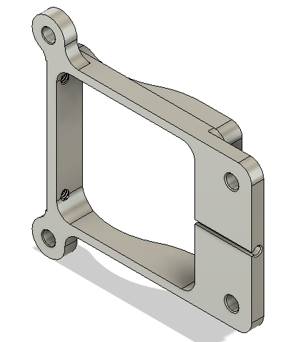
So here’s my spec’d and designed Starter Contactor mounting bracket that will secure the Lamar Superswitch onto the sidewall of my battery compartment.
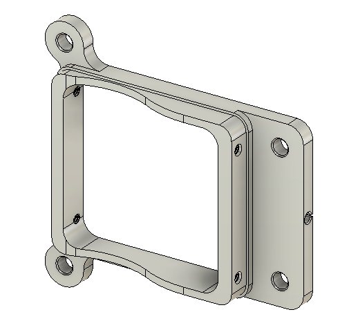
The version above actually had 4-40 screw holes as one of my tasks this morning was to determine the size of the two screw mounting holes located on the contactor’s aft/lower side (bottom/back <unseen> in the pic of the unit at top).
Determining that the mounting screws need to be 6-32 screws, I then reset the diameter and threads for all the mounting screws in the mounting base to this correct size. I also moved the holes a bit farther up. These updates are shown in the CAD sketches below.
The original mounting holes for the contactor unit are to the left in all the depictions of the mounting base shown here. The new mounting holes, which I’ll have to drill into the contactor housing (top edge in pic at top), are the ones located to the right in all these depictions.
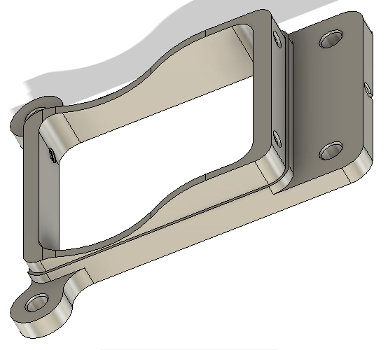
Below is the back side of the Starter Contactor mounting base that is actually shown in the 180° reverse position to how it will be mounted in the battery compartment of the plane.
The cylindrical channel with the slot is for 2 hardwired small diameter red & black control wires (behind, right and top in pic at top) that will be channeled through the mounting bracket to then safely exit out of the unit/mounting bracket combo for subsequent connection into the electrical system.
Of course I’m glad to get this component lined off of my CAD sketch to-do list, but it of course wouldn’t be complete without a fancy rendered version of it! I chose green not because it will end up green, but just to shake things up a bit.
Again, the silver-colored Phillips-head screws are #6 sized screws, while the Cadmium colored mounting bolts are #10 (AN3) sized. I may go down a size to #8 on the mounting bolts, but I’m still assessing that option.
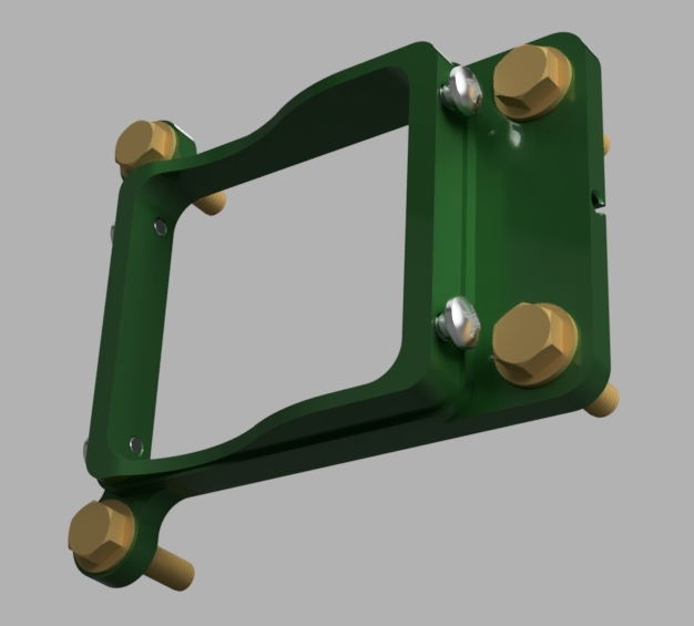
Regardless, I’m calling the CAD drawing and design for the Starter Contactor mounting bracket complete!