
My current back ailment puts me in a bit of an irony at the moment: since I want to take it EZ for a good bit to let my back and hip heal up, I am now actually able to do some much needed administrivia and cleanup tasks on the electrical system. Kind of a catch-22 scenario at the moment in that the longer I delay on getting my house sold, the longer it will take to get back on the build… but in my current state, I’m actually able to focus on a number of aspects of the build. Life can be weird sometimes!
To start off, Bob Nuckolls must be bored (or something!) as he’s been ginning up some new Z diagrams to tweak some of his older stuff. Well, over a year ago he reviewed my basic electrical system architecture and signed off on it, but in the process told me that I didn’t need a relay that I had in place to control isolating (powering) the E-Bus to SD-8 b/u alternator power when/if I had a main alternator failure. I removed the relay to simplify and lighten my system, but never had a 100% warm fuzzy on doing so. I also wasn’t keen on my entire E-Bus being powered via a 15A ATC blade fuse off the Battery Bus. ATC blade fuses tend to be a bit more on the fast-blow side so they are more likely to nuisance trip, so the sizing is a bit more touchy on critical components than say a slower-blow CB.
Well, Bob has since remedied both those issues with a new Z-36 design (see below), which I quickly scarfed up and implemented into my system architecture. Not only does the new Z-36 put the relay back into play, but it feeds the whole E-Bus circuit from a much more robust ANL fuse. Since I wanted to go with a lower amp rating than 30 amps (depicted on Bob’s diagram), I actually downsized to a MINI ANL fuse and will be using either a 15A or 20A mini ANL fuse. During my research, I was also able to find a good fuse holder mount for it and pulled the trigger on it.
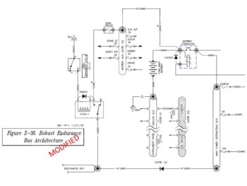
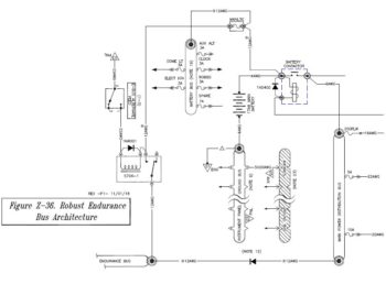 I updated my master electrical system diagram to show this modification, which significantly changed my wiring circuitry to/from the Battery Bus & E-Bus for the b/u alternator power feed, and also the switch circuitry that drives the switching from main to b/u alternator/E-bus power. Luckily, I hadn’t really wired any of that up so I won’t have to do any major rewiring work. Now, while the logic of my configuration matches Bob’s Z-36, my mechanical implementation is just a tad different than his, as I show here (focus on top center of diagrams):
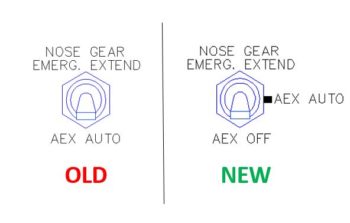
In addition, I spent a bit of time reworking the AEX switch on Marc Zeitlin’s new gear architecture to add an “OFF” position [which, BTW, Marc had in his original design and I am now putting back in based off the advice from Joe Coraggio in his recounting his off-field landing].
My new switch’s wiring is not exactly how I would design it if I were starting from scratch, but it will definitely work and –moreover– will keep the aviation standard of the bottom switch position being “OFF.” It also eliminates any extensive re-wiring other than lopping off the wires from the current switch and re-soldering them to the new OFF-ON-(ON) switch. So, on the new 3-position switch, the bottom position is OFF, the middle position is AEX AUTO, and the top momentary position is Emergency Gear Extend, as shown here.
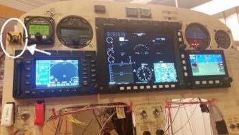
If you’re wondering what switch I’m talking about and it’s location in regards to the panel, I’ve circled it in white and have an arrow pointing to it. Yes, it’s the one in the black and yellow striped switch guard.
I also took a bit of time while adding the new Z-36 design into my system to do an inventory of all my relays and inline fuses. I found a couple of discrepancies in the component ID numbers due to repeated additions, changes and swap outs during system design. I’ve cleaned up the IDs and the lists so I’m up to snuff with both of those electrical system component categories.
My final task related to the wiring was that due to a variety of reasons (from limited behind-panel space to near-max antenna cable run) I decided to place my Trig TT22 transponder out in the right strake pocket and worked up the new wiring scheme for that. I’m actually running the power wires via the CS spar conduit from the hell hole, so that only leaves 4 x 22AWG signal wires that I’ll need to run through a nylaflow conduit imbedded into the lower front LE of the strake. While working the wiring for moving the Trig TT22 out from behind the panel to the end of the right strake, I also finalized the configuration for another (2 of 2) consolidated 22AWG 6-wire cable that will start behind the panel and end in the hell hole.
In addition to working my plane’s electrical system taskers, I’ve also been getting back into the books on flying, IFR and avionics. I’m hoping to get back in the cockpit for another 1-3 months during my transition down to NC to get my flying “sea legs” back underneath me!