
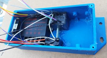
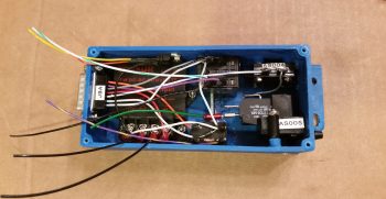
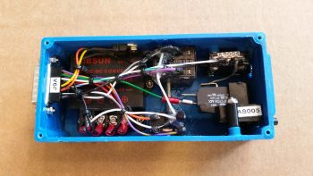
Today I finished mounting all the individual AEM box components and getting it wired up. I was ONE 4-40 screw short to mount the 12V-5V converter in place, so I had to get some hardware at my local hardware store (they have virtually everything!).
Before I left I gooped up both relays with E6000 glue and set them in their respective places inside the box. I then cut a piece of G10 Garolite as a spacer to just fit with very slight pressure against each relay and then slopped on some E6000 all around it as well. With the relays glued to the AEM box on two sides, and a spacer/support installed to keep the bigger relay (note that it’s mounted on the top inside of the box) from vibrating loose and causing issues, I think my non-screw-mounted components will be nice and secure.
BTW, if you’ve never used E6000 adhesive, you’ll understand why I wanted to apply it–out on my deck– and then leave for a few hours…. this stuff STINKS!!!! [You may also note by all the chicken scratches inside the upper right corner that I trimmed the standoffs on the top side down by about 0.050″ to get the top airspeed switch pitot tube barb centered in the sidewall hole].
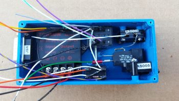
Upon returning from my hardware supply run, and still out on my deck for fresh air, I mounted the 2 airspeed switches into the AEM box. The top airspeed switch (AS004) mounts with 4x 3-48 CS screws while the bottom (AS005) mounts with a 2x 4-40 CS screws.
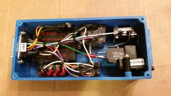
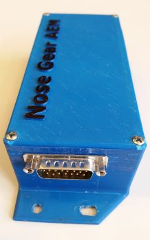
Below is a look at the airspeed switch pitot tube barbs sticking through their respective access holes on the left side of the AEM box. It doesn’t take a lot of pressure to align these barbs, so I tweaked the one on the left a bit after this pic was snapped.
Later in the evening, after a good amount of curing for the E6000 glue (read: way less stink!) I got around to cutting, stripping & terminating the wires with D-Sub pins. For some reason I had my wiring diagram D-Sub numbers inverted from top to bottom, so I spent a good 15 minutes straightening that out. I then started on the wires that terminated into the aft row of the 15-pin D-Sub connector (deeper into the box).
After I performed continuity checks on all my freshly terminated wires, I then mounted them into the appropriate positions on the D-Sub connector.
I then repeated the process by cutting and terminating those wires that are positioned on the forward side of the D-Sub connector (closest to the lid) with D-Sub pins.
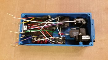
I mounted the last/forward row of terminated wires into the D-Sub connector, and then zip tied the wires to secure them from any vibration damage, wearing or other issues.
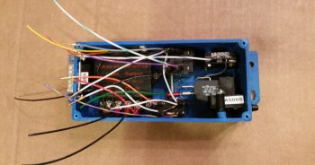
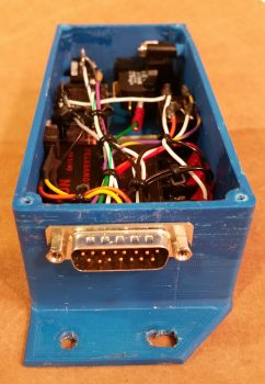
Here’s a shot of the right side D-Sub connector end showing all the installed wires with terminated D-Sub pins.
Luckily it was a nice warm evening, because I then once again took the AEM box out onto the deck to goop up a few of the more sensitive connections with E6000, basically using it as potting material.
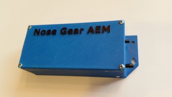
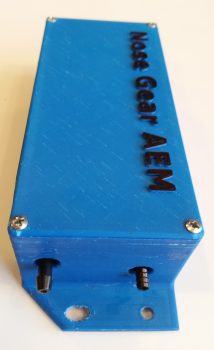
While the E6000 was curing I took the lid and colored the raised lettering with a very high tech coloring system…. sometimes known as a “Sharpie!” ha!
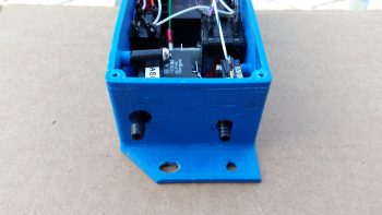
A few hours later I collected up the box and removed some the ‘spider webs’ that are typically when using this type of glue. I then mounted the lid with 4x #4 CS screws.
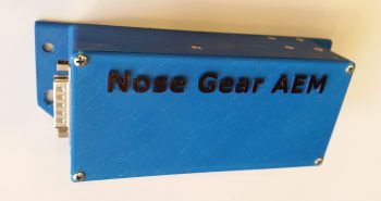
Here’s a clear shot of each end of the box: the J9 15-pin D-Sub connector on the right side, and the 2 pitot barbs poking out of their respective holes for the airspeed switches on the left side.
Barring any issues that may arise when I perform my ops function checks, this completes the construction of the Nose Gear AEM box. I of course still have to wire up the other “B” side of the J9 connector.