I started out today cleaning up the RivNut installed on the triangular panel support. I knife trimmed the excess 2-ply BID layup and pulled the protective tape from the top of the RivNut. I then function tested it as you can see below. Works to plan so far!
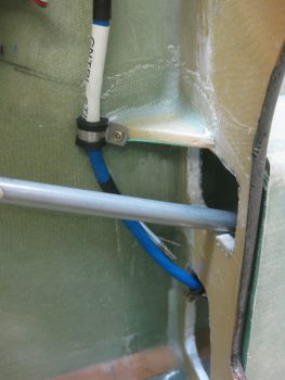
With the new Adel clamp in place for the Infinity stick grip cable, I could then check the proper slack for the cable, mount it in the Adel clamps, then mark the cable for cutting to length.
I pulled the stick grip out and took it to my mad scientist’s electrical laboratory upstairs. Before starting work on it however, I spent a good 1-1/2 hours reconfirming the wiring pinouts for the P5 connector. I consolidated 4 ground wires coming out of the stick grip into 2 wires to give 5 open pins, which enabled me to piggy back 5 wires into the P5 connector: 4 for the roll trim servo (behind the pilot’s seat) and 1 for the ELT GPS signal (like many other builders have done, my ELT will be positioned on the outboard fuselage sidewall, on the inboard side of the right strake’s baggage compartment… so just aft & outboard of my right shoulder). As I was configuring the P5B half (the stick grip side) of the connector, I went ahead and spent another good hour+ figuring out the P5A side of the equation, which is the all points yonder (Triparagon, PQD, panel) side of the connector. It took some time since this process required a good bit of verification & cross-checking with the various electrical diagrams and the component installation manuals.
I had already gotten a late start since I was up late (working on this build!) last night. I ran out to run some errands in the late afternoon and to pick up some small 4-40 stainless steel screws from a local hardware store that still has a wall of hard-to-find hardware in their back room. When I got back I toned out all my stick grip wires to check continuity and verify wire colors, since I had swagged some guesses on them as I was building the P5 pinout diagram. With my P5 pinout up to speed, I did some prerequisite tasks for terminating the P5B connector onto the stick grip such as printing out shrink tube labels. For the 5-wire roll trim piggyback cable I checked availability of parts, since I have 4-pin mini-Molex connectors on hand and I need at least a 5-pin (which actually means 6-pin). Again, I don’t want to use a 9-pin D-Sub here, so I added a couple of 6-pin connectors to the Stein order that I’m compiling. Boy, it’s an obvious statement I know, but the nit-noy parts buying process for these builds is ENDLESS!
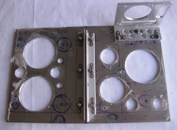
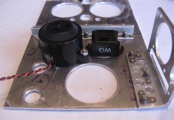
Ok, with it being a bit later in the evening, before I started on the terminating the P5 (B side) connector on the Infinity stick grip cable, I wanted to make a decent amount of noise on the Triparagon cross shelf. Thus, I detoured from the stick grip cable for a bit to drill 10 new lightening holes into the cross shelf — 8 small diameter and 2 bigger diameter holes. The 2 bigger diameter holes, just to the right of the center brackets in the pic below, sit immediately above the mounted Piezo warning horn (bigger, lower hole) and the gear & canopy warning module that I mounted tonight (see next pic).
Yes, folks, it’s the marvel of modern technology! Getting a gear & canopy warning module into the space of a couple of stacked matchboxes . . . why it’s just pure science! (ok, and integrated circuits… ha!) Not wanting to NOT gain any progress on the Triparagon today, I mounted the nose gear & canopy warning module with some -6 CS SS screws. As per usual, I drilled the countersinks on the topside of the Triparagon cross shelf, although admittedly one of the holes didn’t want to cooperate and the countersink is a bit larger, lopsided, and messier than I would prefer. Still, once the screw is in & the module mounted it would be bit difficult to tell unless really looking hard at it.
I brought the Triparagon cross shelf back upstairs and weighed the whole thing without any mounted stuff. It currently weighs in at 0.57 lbs, which when added to the Triparagon vertical plate at 0.7 lbs gives me a current total weight of 1.27 lbs. This is about a quarter pound heavier than my 1 lb goal weight. The prescription? I gotta fever for some more lightening holes! So back to the drill press for another round of sharp-bladed weigh loss!
I then started (finally!) on terminating the Infinity stick grip cable wires for the P5 connector, B side. After taking a big breath and cutting the cable to length, I then slid the plethora of heat shrink tubes & labels onto the cable. I then cut the outer cable jacket to expose the 17 inner wires.
I didn’t take a bunch of sequential pics, so here’s what I did: I started off having to find & verify the pairs/groups of wires for each switch in the control stick. As I found each new set, I would strip the end of the wires, terminate them with an AMP CPC socket, check continuity, and then mark them off the list. I also used small pieces of masking tape to keep the pairs/groups of wires together. After I terminated all the wires, which included 2 sets of 2-pair ground wires, I then double-checked the electrical continuity and then snapped them in place into the correct numbered socket hole. I then rechecked continuity again just to ensure I had gotten it all right… which I didn’t. I swapped the 2 green wires and had to pop them out and reinsert them into the correct socket positions. I toned out the entire cable again to ensure the sockets were in the correct position with electrical continuity, which they were.
I then went down to the shop, measured the required length of roll trim & ELT GPS pigtail legnths at 10.5″. Instead of using the 5-wire cable that I have (you’ll see that in pics tomorrow), I decided to simply use free 22 AWG wires. I actually started collecting the wires with the correct color codes (ie white with blue stripe, etc.) when I realized that instead of wasting my good multi-colored wire, I would simply use white wire and use a Sharpie to mark the correct color on the last couple of inches of the wire. For the the two plain white wires in the bunch, I simply swapped out the white wire at pin #2 for a grey wire, so no confusion would set in while I await my 6-pin mini-Molex connector from Stein. I then terminated the 5 each 22 AWG pigtail wires with mini-Molex pins.
I then terminated the other end of the 5 pigtail wires with AMP CPC sockets. I verified that my crimps on the terminated wire ends were good by doing a continuity check on each wire.
To keep the 5 pigtail wires under control, I threw on a small piece of black heat shrink.
I then snapped the pigtail wires into their appropriate socket holes in the back of the P5 connector. I also went to town on the cable with my heat gun and shrunk all the shrink tubing and labels in place.
I then did a final continuity check on the pigtail wires, and with that all that was left to do was to mount the cable clamp, that I conveniently did not forgot to put on the cable this time!
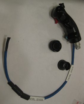
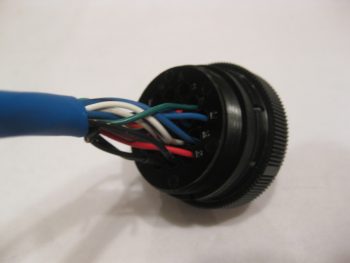
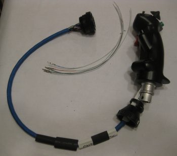
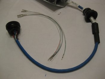
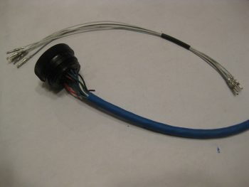
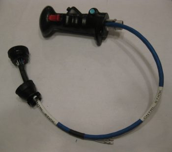
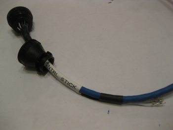
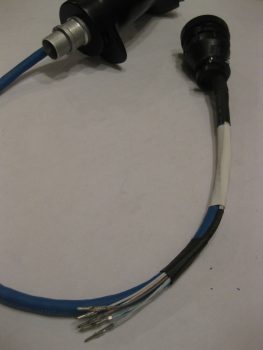
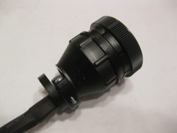
Here’s the Infinity stick grip cable terminated with the P5 AMP CPC connector and 5 pigtail wires that will go into a 6-pin mini-Molex connector. If I wasn’t clear on the pigtail use before, it will allow the 4 roll trim/1 ELT GPS wires to transit into the P5 connector, but still allow me to disconnect the roll trim/ELT GPS cable at the 6-pin mini-Molex connector when I simply want to remove ONLY the Infinity stick grip and cable from the plane. Clearly, in this scenario, once the 6-pin mini-Molex connector is disconnected the 5-wire roll trim+ELT GPS cable would remain mounted under the right armrest.
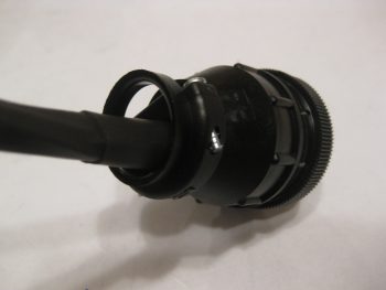
Here’s a couple closeup shots of the P5B connector with the cable clamp in place.
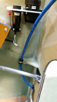
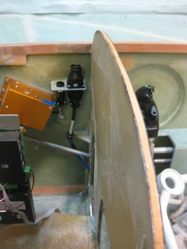
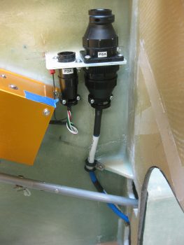
I realized as I remounted the control stick, ran the stick grip cable and screwed the P5B connector onto the P5A connector at the P3/P5 mounting bracket that I’m going to have to carefully trim the back outboard corner opening of the armrest to get that big mojamma P5B connector into the armrest! After that it traverses through the lower instrument panel bulkhead hole fine.
Also, I’m very happy with the stick grip cable run since it keeps the cable nicely tucked out of the way from the elevator control tube range of motion.
Here’s a final shot of the freshly terminated stick grip cable connector and installed cable.
Tomorrow I will continue to work on the 5-wire roll trim+ELT GPS cable and try to finish up the Triparagon installation.

