
Today I actually started off adding a couple of more shielded wires to my Dynon Intercom wiring harness connector (no pics). With the 2 wires I knocked out today, that puts me at about halfway done on that harness. In fact, I’ve got one more wire to add and then I’ll call it done until final install. Why? Well, the majority of the remaining intercom harness wires come in from the relay that controls the COM1/COM2 selection functions for the intercom. And I can’t wire that up until I’m close to going live.
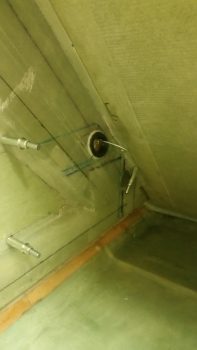
I then started back in getting the jacked up situation from yesterday straightened out. I decided to bite the bullet and simply add another 3/16″ piece of Nylaflow –which will carry 3 wires– from the left sensor cover over to the right and then a 1/4″ piece of Nylaflow –which will carry 6 wires– from the right sensor cover over to the right sidewall where the wires will merge into the small wire bundle that traverses the side of the fuselage.
I measured out what I needed and cut a piece of Nylaflow. I then dry micro’d some around the Nylaflow to attach it and glassed in a ply of BID over each end. I have to tell you, even this endeavor was just being a royal PITA! [I 5 min glued it the front wall but for some reason it just did NOT want to stay in place . . . ]
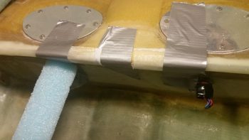
After much wailing and gnashing of teeth, I finally got the Nylaflow settled in close to what I wanted and after each end was cured, I then glassed a single patch of BID in the middle to finish off the 3/16″ Nylaflow conduit install.
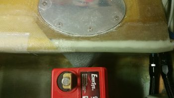
I installed the left sensor cover in place using 5 min glue on 2 adjoining sides and silicone RTV on the other 4 (It’s hex shaped). I then used my main battery to keep it in place while it cured.
A little while later, after the middle patch of BID cured, I then micro’d and glassed in the second piece of Nylaflow conduit, only this one was 1/4″ as I mentioned above. I also used 1 ply of BID as I did before.
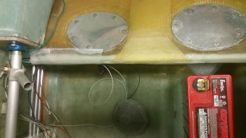
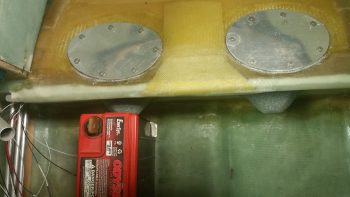
Even more of a while later I then 5 min glued & RTV’d the right sensor cover in place. To be clear, I tested the LED lights in each sensor cover before securing them in place.
I will say that with this smaller Nylaflow conduit sitting right below the 3/8″ Nylaflow above it, the lip created by the top big Nylaflow conduit complete eclipses the lower conduit and you just can’t see it.
BTW, I’m covering the pictures by subject in this post versus jumping back & forth, but in reality I did go back on forth on these tasks.
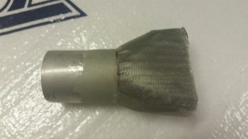
During cure times above, I took a piece of urethane foam and shaped it to create an exit duct out of the top of the main duct that moves the air to the GIB upper duct vent. I cut a piece of 1.25″ diameter 6061 tubing that I ordered specifically for these ducts… mainly because that’s the diameter of the eyeball air vents that I have on hand. In addition, I also ordered some Skeet tubing as well, but it’s on back order with ACS.
I then prepped the foam for glass using duct tape. I of course left the 6061 tubing clear since it will become an integral part of the upper duct vent transition.
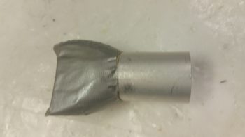
Since the air will curve a bit “up” (all relative here) coming out of the duct, unlike the lower GIB duct vent, I decided to create 4 sides to the duct transition (transition from the fiberglass duct to Skeet tubing and then to the eyeball air vent) so I needed to get the “bottom” of the duct transition glassed first. Thus, I glassed the bottom with 1 ply of BID and peel plied it.
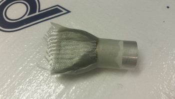
After the BID cured I pulled the peel ply.
And then trimmed the glass.
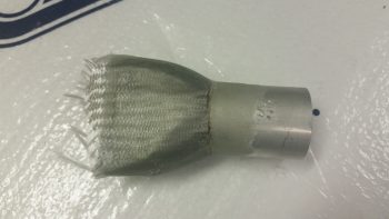
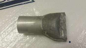
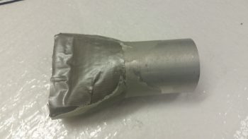
Here you can see both sides of the upper duct transition vent.
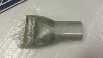
I then set the initially-glassed duct transition vent in place in the top of the main duct channel and taped it up in prep for final glassing.
I then laid up a small ply of BID just over the top of the foam piece area (taped) for strength, and then laid up a ply of UNI and a ply of BID to create an overlapping flange on the existing duct. I of course could have created the entire duct transition piece to fit inside the main duct channel, but I wanted to optimize airflow as much as possible.
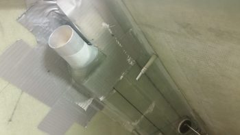
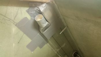
And here’s a bigger picture view of the GIB upper duct vent transition and the rest of the duct network. If you’re thinking maybe the duct transition piece is a bit too high, you may be right. But I’ll be able to adjust the height through trimming down the aluminum tube length and/or hacking off some of the main vent channel if need be.
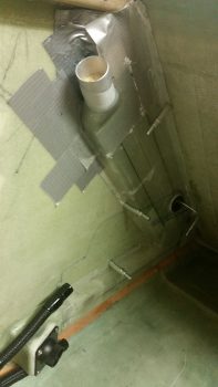
Here’s a bit clearer shot of the fresh air / heater air valve with the control arm clearly visible.
Tomorrow I’ll continue to work on my GIB area tasks. As you can see, I’m nugging it all out and getting significantly closer to being done in the back seat area. That being said, I will be receiving out of town visitors late tomorrow night. They’ll be here until Sunday, at which point I’ll be heading back down to North Carolina for nearly a week. However, when I return I should have no further distractions until I head out to RR.