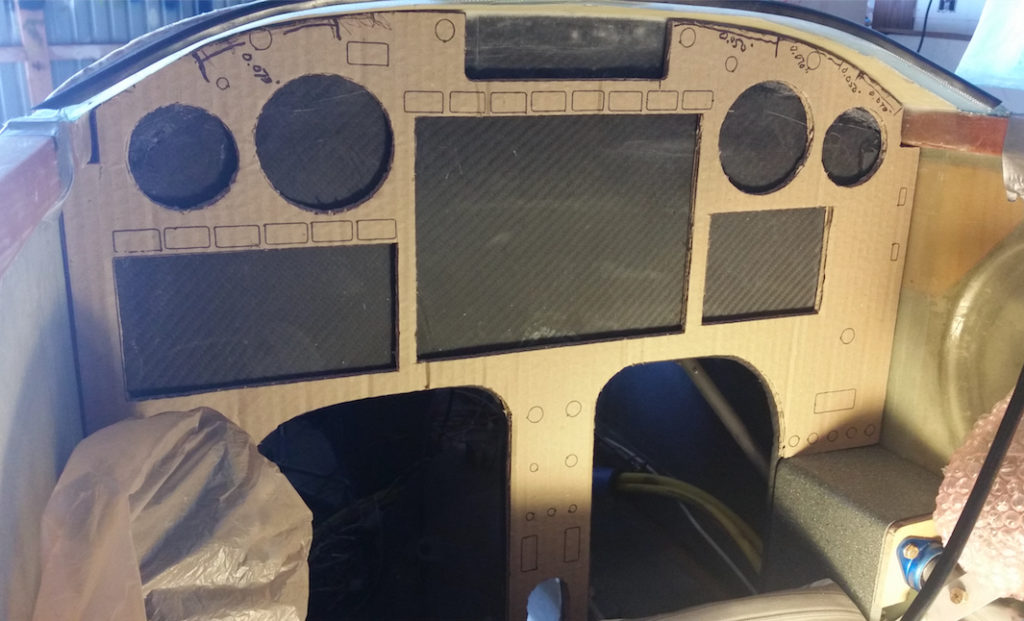
Today I was able to test fit version 2 of my instrument panel cardboard mockup. I’ll reiterate that I feel that it would be infinitely easier to simply trace out, cut a panel by hand and then mount it than it is to constantly fiddle with drawing up the instrument panel in CAD to fit the existing composite panel structure . . . again, especially at the top curve and leg cutout curves.
However, since I do have a bit of time available to do draw up and check the panel –since I’m still in the amazingly protracted process of moving down to NC– in the long run it will be so much better to have a match-fit panel available in CAD if I ever want to do any panel upgrades, improvements or overhauls. The ability to plan and fit on “paper” in CAD will make any future (and has definitely been proven during current planning machinations…) upgrades or additions much, much easier to handle.
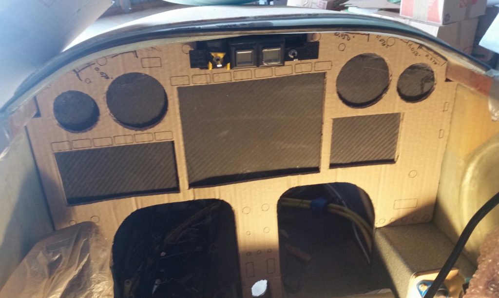
Clearly the major change between panel version 1 and panel version 2 is the notch made top centerline to incorporate the warning annunciator sub-panel. Since we didn’t print out all the switch positions with the marker, it’s not easily identifiable to note that there are a couple fewer switches on the panel.
Panel version 2 fit much better than version 1, most significantly at the leg holes. The top curve still offered up a few challenges, but that should be easily remedied but just one slight shaving in the upper left corner and lopping off about 0.030″ on the bottom corners just above each arm rest.
In addition, I do plan on moving ALL the instruments and avionics up about 0.15″ to create a wider crosspiece just above the leg holes.
Although I didn’t get a shot of it, I also checked my 3D-printed model of the new style (to me) canopy latch handle structure. I’m very pleased with the size & configuration of the new canopy latch handle and really do think it will work out really nicely and provide the required clearances with the F-15 throttle handle and the Garmin GNS-480 GPS.
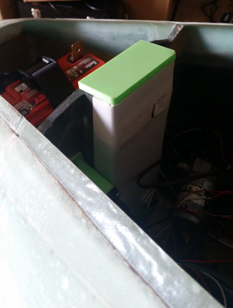
I also checked out my one-off design for the NG-30 uprights’ hole cover. I had to trim a bit off the bottom back edge for it to slide into place, which tells me I need to angle that piece.
It fit generally well, but I do have a long list of tweaks that will need to be made for it to fit in a truly acceptable way.
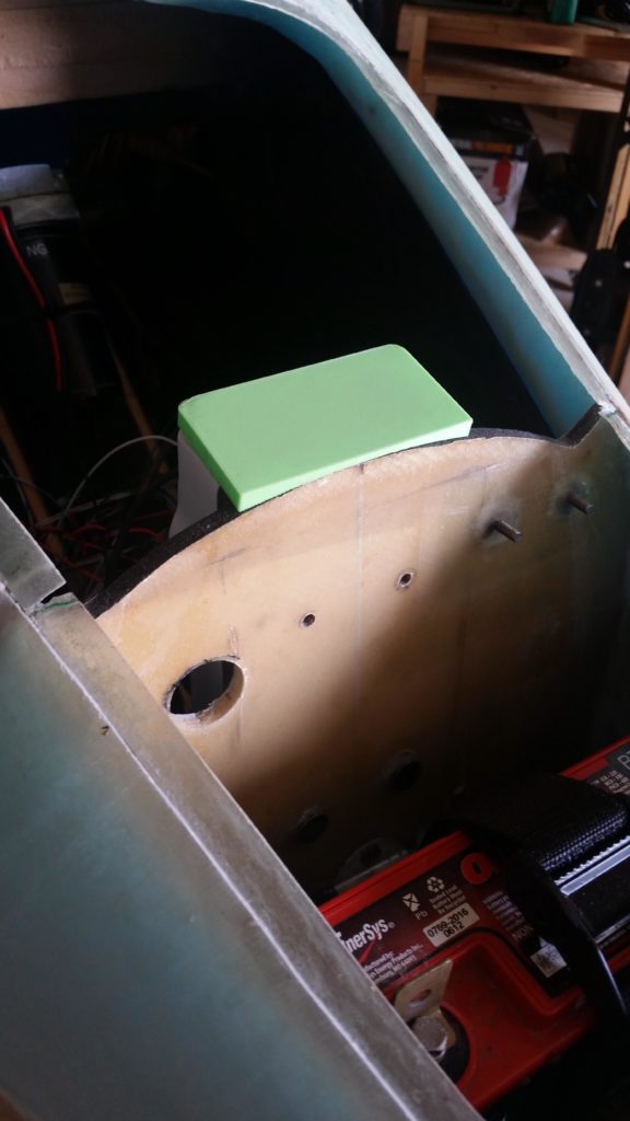
One critical design change that I must make on this hole cover piece is that its height will have to be reduced at least by 0.1″ on the outboard edges. When I tried to place the nose hatch cover back into place with this cover piece in place, there was a slight gap caused by the lack of clearance between the nose hatch door and this cover piece.
Still, I think I’m off to a good start and this will eventually get there design-wise as well!
I also did a fair amount of organizing and cleanup of the hangar, as well as an attempt to track down some hardware that is eluding me at the moment. Overall, with my dimensional notes in hand as I head back north, it’s been a fairly productive trip build-wise.
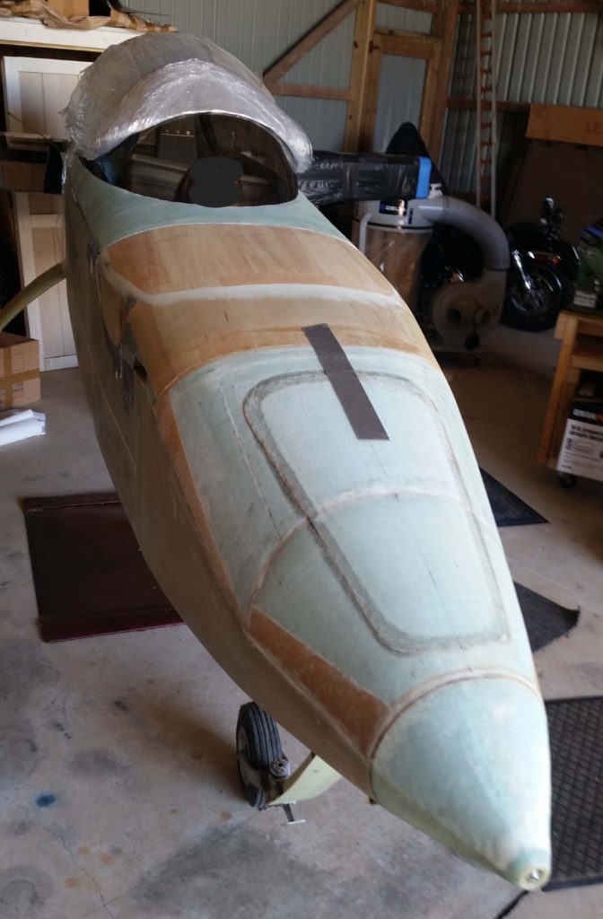
I added this pic below after the original post… it’s a pretty good shot of the nose and canopy (I blocked out the face of my friends’ daughter, who wanted to sit in the plane, since they don’t care for pics of her on the internet).