I started off this morning reading an email from my buddy Dave in OZ extolling some issues on placing the latch for Jack Wilhelmson’s RL-1 Canopy Rotary Latch system. Dave has too many interfering components, including the left knob on his Garmin GTN650, if he tries to put it in the traditional location just in front of the left side of the instrument panel. Just as a point of note, that was seriously a big primary reason why I went with the GNS480: no left knob except the on/off/vol knob, which is still however my own limiting factor for moving my RL-1 latch up as close to the panel as I’d like.
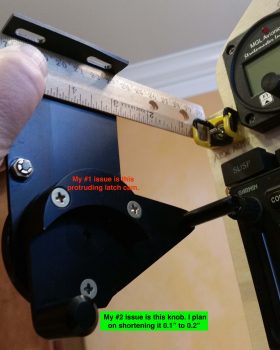
Well, curiosity got the better of me, so I grabbed my latch and mocked it up… I was aiming for the plans’ ~4″ in my head and mocked it up quickly, realizing immediately after I took the pic below that the longer lever doesn’t reach forward as I have it in the pic, it only just travels between the 7’ish to maybe 1 O’clock position (as I understand it).
I pulled out the installation manual and had in my notes to move the whole canopy latch shebang 1.4″ forward to allow clearance at the rollover assembly and also for the throttle. Dave’s solution looks to be mounting it mid-strake opening, thus turning it into a center controlled latch with the small catches forward and aft of the main latch, where as obviously both are aft on the plans style latch.
Since I can’t really do what Dave is doing (since Dave is building his Long-EZ to fly around the world, he has no fuselage cutouts into the strakes… the fuselage sidewalls are the interior walls of the fuel tanks), my issue becomes one of tight tolerances and clearances.
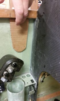
Although the cardboard cutout I made as positioned below is ~1.4″ inches forward (F.S. 42.6) of the plans’ position (F.S. 44), allowing clearance for the throttle, this position has the short fat rotary latch knob hitting my GNS480 on/off/vol knob. Moving it aft about 0.2″ provides clearance for the knobs, but only gives me about 1/4″ clearance from the outboard top edge of my CURRENT WOT throttle position to the robust, square-edged latch cam I note in the pic above (noted as “#1 issue”).
Thus, I provide Wade’s 3-point plan for eaking out just enough room to make this work:
1. Ensure the rotary latch assembly is driven as far outboard up against the sidewall as possible when mounted to better provide clearance between the latch cam (top pic) and the outboard edge of the throttle handle. BTW, the throttle handle’s outboard edge aligns vertically very closely with the inboard edge of the longeron (if you drew a line or strung a plumb bob and viewed it from top/aft/front), so there is clearance… but I just want more for my poor pinky! Also, regarding the clearance between throttle and canopy latch, the real issue is only during T/O and climbs at WOT.
2. I still need to drop the throttle down when I construct the new throttle lever. With the canopy latch position required to be a hair aft of where I originally wanted it, I may cheat a bit and drive the throttle inboard say 0.1″, and mount it lower (the handle, not the quadrant) the furthest it will go comfortably.
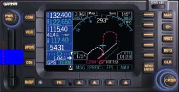
3. There’s approximately a 3/4″ gap between the front of the rotary latch’s smaller fat knob (depicted blue above) and the GNS480 face when the rotary latch is locked and closed. Again, this is approximate of course since I don’t know the exact resting position of this knob, but it is close to what I have shown above. This shorter latch knob will also just barely clear the bottom front edge of the “PWR/VOL” knob. However, since I come in at a slight angle from the right anyway to push the CDI button (XPDR button is inop in my setup), the short fat knob if left alone wouldn’t present a big problem. But by driving the rotary latch assembly as far outboard as possible AND trimming about 1/8″ off the bottom (outboard) of the knob to reduce it’s overall protrusion into my GNS480 op space, I should have zero issues for any 480 button-pushing tasks that may ensue.
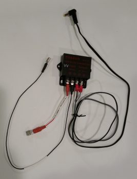
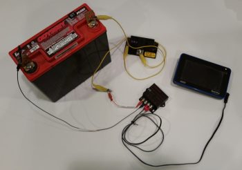
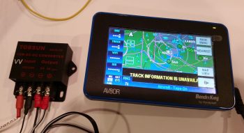
Moving on… After the above shenanigans, I then prepped a small “toy” that I just received in the mail: a 4.0mm OD x 1.7mm ID corded jack to power my Bendix/King AV8OR backup GPS. I determined a good length for the cord and ended up cutting off about half of it. I then cut each end of the cord’s 2 conductors and spliced on cheap ring FastON terminals since later I’ll make both a final cord length determination and possibly run GPS and video camera leads into one ring FastON connector –since they’re so small– for both the 5V pos & neg connections. As you can see below, I then hooked up my new GPS power jack to the terminals on the 12V-to-5V converter.
After testing the output of the AV8OR’s original wall mounted charger (5.196V) vs the 5V output coming off my 12V-to-5V converter (5.231V) and determining that the values were very close, I then connected the converter to 12V battery power through a 3A fuse. I then plugged in my Bendix/King AV8OR GPS unit and immediately saw the amber power in/on LED light up. The lack of smoke, fire or popping fuse was also a good sign . . . ha!
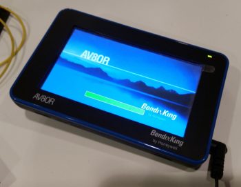
I then pressed the ON button of the AV8OR and it fired right up.
As with most GPS units, it took a few minutes for it to find its bearings, but it then perked up and functioned as normal. I’m very pleased to be able to have a hard-wired cord to use to power/charge this backup GPS unit without having to use up a cigarette charging port and contend with the bulky AV8OR car power charger.
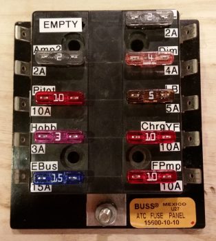
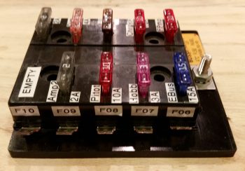
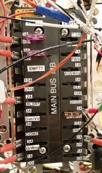
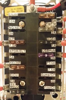
I then finally rolled up my sleeves and took a few hours to label my busses with the appropriate fuse size and a very truncated description that has just enough characters to tell me what the fused item is. Keep in mind that the labeling of these busses is for operational ease and quick fuse terminal position ID, possible troubleshooting, and/or system design updates. Although I was aiming for neat, orderly and legible, I am NOT trying to win any beauty contests here, nor win the “Straightest, most-aligned label of the Year” award!
I started off by knocking out the Battery Bus. Point of note is that after all these pics were taken, I did actually go back with bigger white on black labels for labeling the bus itself with “BATT BUS – BB”
Since I’m focusing on labeling the front of the busses, I thought I’d include a pic of the actual side terminal labels, which is depictive of the other busses as well.
I then knocked out the Main Bus. If you have good attention to detail, you may note that the main bus has the fuse amp size listed above the fuse with the fuse circuit ID below it. I already had a bunch of these labeled so I left this scheme in place on the main bus. Not a huge deal, but I like having the actual fused component ID on the top for better visibility, so I changed it on the E-Bus.
I went out for a bit to buy some groceries and make dinner, then afterwards I knocked out labeling the Endurance bus (E-Bus). Again, I also made a bigger white on black label and attached it to the center vertical area of the E-Bus just as I did for the Main Bus above.
In closing I have one small, but significant, development to report. I had a good phone conversation with Marco today and during it I was conveying my frustration with the OAT readout on the MGL clock. Since the MGL’s degrees Celsius reading is an integer, with no decimal, it makes translating between Fahrenheit and Celsius a pain since the MGL is simply off a degree or two from the HXr EFIS due to this poor equational translation. If I could, I would merely shut off the OAT display on the MGL and be done with it.
This led to Marco asking if I had 2 GRT OAT probes and I responded I do, one connected to EIS4000 and one connected to the HXr AHRS unit. Note: this is essentially feeding two OAT data points into the same system, for simple redundancy. He stated that he has one OAT probe connected to each of his 2 Mini-APs and displays one on Fahrenheit and the other on Celsius.
Ah, ok, this still provides redundancy, but allows each EFIS to control how it wants the OAT displayed. To be clear, this is most likely possible no matter what or where the actual OAT inputs are located, but the point is that I have a dedicated OAT port on my Mini-X that –after some thought and assessment– I’ve decided now to employ for OAT probe #2 rather than mess around with it back in the D-deck/Turtledeck area. Since I wasn’t clear on how I was going to mount the aft OAT probe this puts that question to bed since the forwards mount into the nose wheel well (into NB) quite nicely.
Thus, I pulled the OAT wire out of the EIS4000 harness and updated all associated wiring and connector pinout diagrams.
Tomorrow I’ll continue to work miscellaneous electrical taskers, with the rewiring of the seat warming pads –to replace auto wire with aircraft grade Tefzel wire– coming up soon.

