
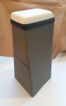
Yesterday I got some rubber “T” molding that is used at the edge of auto windshields and the window frame for sealing a windshield edge. I bought it off of Ebay because it was the only source of supply I cold find (I looked a while!) and had it shipped in from China. I checked it out a bit last night, then this morning I trimmed it and mocked it up atop my pilot seat headrest (which will get repainted with my now standard interior scheme color later). The molding looks like it will do a great job for it’s intended purpose of securing the GNS480 GPS antenna puck cover (aka “radome”) in place, given that I don’t have any glue, tape or anything securing the pieces together in the pic below.
I spent a few hours this morning replying to emails and updating my electrical diagrams in what appears to be a fairly controversial move on my part. I’ll start by providing some background on my quest to find information on optimizing the firewall components’ layout and engine wiring transition through the firewall.
I remember reading about Brian DeFord’s Cozy burning up on the ramp due to an electrical issue at the firewall. I’m still not 100% clear as to what caused it, as he may not be either. It was a tragedy and I’m sure heartbreaking for Brian, but I’m glad both he and his beautiful family were safe from harm in this incident. One thing that Brian mentions is that he did not turn off the master switch at the first telltale signs of smoke, and within 20 minutes his stellar Cozy IV lay in a pile of ash with only the engine and winglets pretty much left.
This led of course to some major discussions on the Cozy forum and other venues about hot wires transiting through the firewall. In my research I discovered a question asked by Greg Norman [I know Greg from RR16] to the Cozy forum specifically about mounting the starter contactor/solenoid on the cold side of the firewall. There was fairly overwhelming consensus in those that replied that stated mounting the starter solenoid on the cold side of the firewall kept from having to have the big power wire traverse the firewall.
As I assessed this, I came up with a number of pros as to why I concurred that it was a good idea:
- In keeping the main power cable from transitioning through the firewall, it simplifies the corrective action for smoke or malcontent coming from the engine compartment in that the only hot wire going through the firewall (before start… after start there is of course the alternator B lead) is caused by the starter button/switch being engaged. To remedy a hot wire to the starter and cut power one merely STOPS pressing the starter button/switch.
- As per above, this makes turning off the Master Switch less of a critical step to remedy something electrical-related being amiss in the engine area to more along the lines of probably a good idea thing to do.
- The ancillary logistical benefits of moving the starter contactor to the cold/forward side of the firewall in routing wires is quite significant. It simply makes for running less wires through the firewall, wire runs to the Hall Effect sensor for both the primary and SD-8 backup alternators are optimized, and it places more items in the rather empty Hell Hole area and gets them off a very crowded firewall, just to name a few benefits.
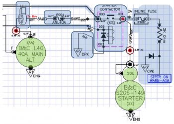
- Below is a diagram I made to explain this. Prior to my decision to move the starter contactor forward to the cold side of the firewall, everything in the diagram below was mounted on the hot/aft side of the firewall. The main big power cable coming from the nose mounted battery contractor is the big line at the very top left half of the diagram. Now that I’ve moved the starter contactor (planned, not executed …. yet) everything in blue is on the cold/forward side of the firewall while the alternator and starter are of course still mounted to the aft side of the engine.
Thus, in short, moving the starter contactor forward to the cold side of the firewall just really appears on the face of it to make for an easier install and a safer operational setup. Honestly, I might not have done it if there wasn’t the overwhelmingly increased ease of wiring it provides.
[I should note that I posted this as a question on the AeroElectric Connection forum, and in my discussion with Bob Nuckolls he does NOT seem to be a fan of moving the starter contactor to the forward side of the firewall. I will also state that I have not received any clear reason from anyone, including Bob, up to this point as to why it would NOT be a good idea. I have had a number of Cozy/Canardians say that they are or have done this, and are glad to have made the change. Understandably, the folks who seem the most unenthused about this idea are not canard/pusher pilots/builders, but tractor aircraft drivers].
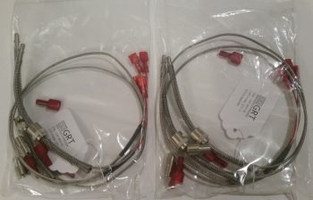
Moving on from the controversy, today I received the missing EGT probes from GRT…
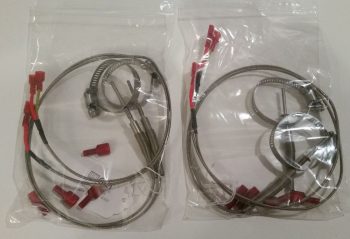
and the missing CHT probes. Thus I’m calling The Case of the Missing EGT & CHT Probes SOLVED!
I then got to work on at least getting one electrical task knocked out today. Since I was already dealing with the starter contactor I decided to build the circuit that is used by the AG6 warning annunciator to alarm during engine start with a “Starter ON” annunciation. If this red alarm annunciation does not turn off after engine start, or after a failed start attempt, then it tells me that the circuit is still live and that I need to take immediate corrective action (probably very close to what happened to Brian DeFord in his Cozy burning-up incident).
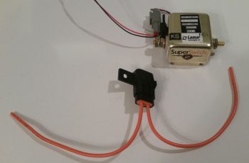
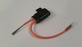
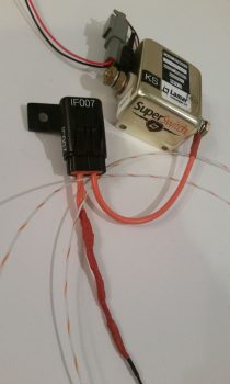
The circuit for the AG6 Starter ON warning cohabitates with the Starter lead on the downstream side post of the starter contactor, starting off with a 2 amp inline fuse [Note: The wiring diagram for my task here is shown in the diagram above on the right side of the page]. I grabbed another mondo-wired inline fuse assembly and assessed its eventually mounting in the vicinity of the starter contactor.
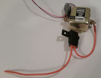
I then trimmed one leg down a bit, stripped the wire back and crimped a blue PIDG 0.25″ ring connector onto the end of the trimmed inline fuse leg. When I crimped the terminal in place I clocked it so that it would be vertical while the body of the inline fuse housing was flat against the firewall. Of course I had preloaded the wire with a piece of red heat shrink to place over the terminal after I crimped it.
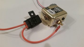
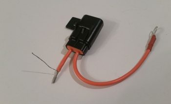
Here’s another shot of the 2 amp inline fuse for the AG6 “Starter ON” warning annunciation lead.
I then hacked off the other leg a little over half-way.
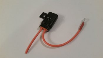
I stripped a big portion of the insulation away.
I then teased out around 4 wires to create a pigtail for wrapping around the component leads for a tight junction when they would get soldered onto the lead.
When I talked to Rich at Aircraft Extras regarding the installation of the resistors for the AG6 warning input leads, he said the install manual required 2K Ohm 1/2 watt was a good ballpark for what can be used. After that discussion, I’ve used 1.5K Ohm and 1/4 watt resistors on other AG6 leads without any concern. But here, with this being connected on the same post as the one item that sees the biggest inrush current on the entire aircraft, I wanted to go with what’s called out in the AG6 install manual…. as a minimum.
The problem was I was out of 2K Ohm 1/2 watt resistors. Hmmm? Ok, well, I guess two of those 1K Ohm 1/2 watt resistors in series will just have to do! So, I improvised, adapted and overcame … and pressed forward with my 2 resistors in series.
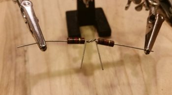
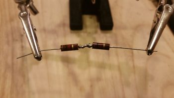
I then soldered the two 1K Ohm 1/2 watt resistors together….
and trimmed the excess leads.
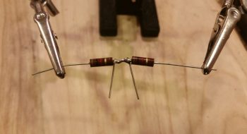
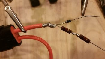
I then (mistakenly . . . sheesh!) tied the resistor set and a diode together at the end of the 2A inline fuse lead.

And soldered that up. But something wasn’t right. Yep, strange things were afoot at the Circle K. When I checked my diagram I quickly noted that I had tied in the diode at the wrong point.
So I snipped the diode off and soldered it in parallel with the white/orange lead that heads off to join up with the white/orange lead from the 6-wire cable that heads up to the panel avionics area. The diode that I relocated is a protective diode that simply goes to ground and protects the line from any massive amounts of juice from frying anything.
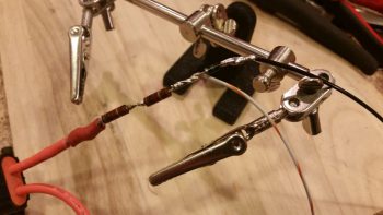
I then added protective heat shrink to the whole shebang and called it good.
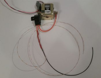
And then did some labeling of the inline fuse housing (“IF007”) as well as the inline fuse housing I configured for the SD-8 the other day (“IF008″… not shown). Of course when I get some more wire labels here in another week or so I’ll label up all the unlabeled wires I’ve just created over the past week.
Besides all my crazy antics above, I also did a fair amount of research and identifying what to buy for the next round of electrical tasks. I really think the parts requirements for the electrical system will continue to dwindle exponentially over the next few months as I get closer and closer to dialing in the electrical system to its final state. And again, tomorrow will be more of the same on knocking out electrical system tasks.