
After spending a good bit of time in the AG6 warning annunciator manual last night, I started off today once again with about 1-1/2 hours of updating my initial electrical diagram for the dual AG6s I have installed. I had originally only had the AG6s on this diagram with all other warning circuits listed in diagram 16, which specifically has a small housed module for the gear & canopy warning annunciation (shown below) along with the other warning stuff.
However, since I pulled all the individual warning LEDs off my panel and routed them all through my AG6s (the exact reason why I bought another one) it stands to reason that to show those circuits ALL warning circuits other than the gear & canopy warning module needed to be on the AG6 wiring diagram page while only the gear & canopy warning module wiring is depicted now on diagram 16.
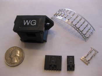
I also realized after looking to copy a pic of the AG6 annunciator to show in this post that I may have never actually posted a pic of one. These are stock pics below from the company who makes them, Aircraft Extras, Inc.
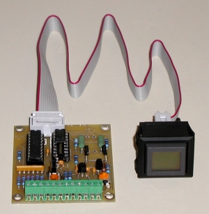
Here’s the entire system, with the boards mounted back-to-back on the upper Triparagon. Each board will have 6 warning circuits for a total of 12 and will display on a button that can be pushed in to acknowledge an alarm state. Of course 2 AG6s means 2 display buttons on my panel.
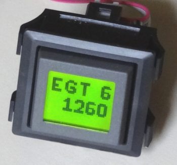
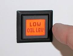
There are 3 available background colors for the AG6 display screens: red, green and yellow. Below is a couple representative pics of the red & green displays.
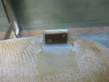
I also couldn’t find a shot of the JBWilco gear & canopy warning module that I’m using in my system. I picked this up from a guy who built a bunch of them after he designed it for use in his Cozy. He got tired of making & selling them, and I just happened to contact him right as he was selling his very last one.
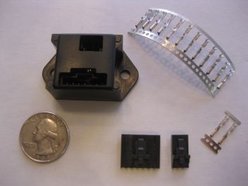
As you can see, this module is very small and very light. This will actually drive a pair of red & green LEDs on my panel. These will be the only LED warning lights on my panel, since I’m wiring the Wilhelmson gear & landing brake LED pairs up to the AG6s to display gear up/down and landing brake up/down. This module will sound a warning for the gear & the canopy, both visually through the LEDs and also through a warning buzzer. BTW, this gear & canopy module will be the only warning that uses a buzzer. I may configure other warnings to provide audio warning tones, but those will all be driven through the EFIS and only be heard via headphones.
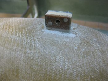
Down in the shop I cleaned up the aft lower Triparagon mounting tab. I didn’t like the way the lower glass was attached on this tab from my original 2-ply BID layups on the right side of the nutplate mounting hard points, so I ripped off the glass and sanded it down to remove the stubborn stuff.
I also took the time to clean up the other tab layups, ensuring the edges were sanded down smooth. I also drilled out the remaining holes in the glass for the mounting bolts. All this sanding, trimming and drilling made a bit of a mess….
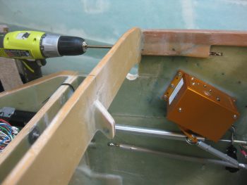
So before I vacuumed it all up, I decided I would make just a bit more of a mess by using my long 1/4″ drill bit to expand the #10 holes in the longeron doublers + the new extensions. The 1/4″ hole is for the 4130 sleeves that will provide a solid channel for the long AN3-62A bolts that I will employ on the top canard alignment tabs vs. the plans alignment pins. This is a mod I had seen in passing before, but I really took note of it after checking out what my buddy Dave Berenholtz was doing on his upper canard alignment tabs.
I drilled the left side first.
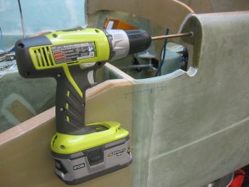
And then the right . . .
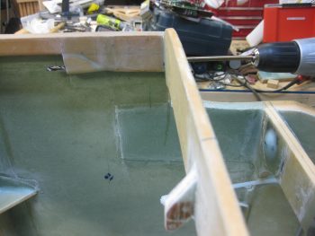
After my short 5-min drilling task detour, I then vacuumed up the mess I had made in the avionics bay area. I then grabbed a small piece of plastic and prepregged 2 plies of BID and laid up the aft lower Triparagon mounting tab. As you can see, and not surprisingly, I then peel plied the layup. What you don’t see is that I then lightly clamped the same block of tape-covered wood that I used before to compress the glass a bit. Finally, I used the leftover epoxy to seal the exposed bare foam on the 3 edges of each Triparagon nutplate mounting point.
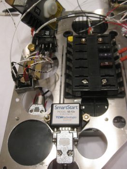
With the lower mounting tab BID curing, I then took the Triparagon upstairs to finalize the on-board wiring cross-connects. I started by printing out a number of wire labels on the white shrink tubing. I then terminated two 22AWG red wires into one FastOn tab, one leg each to power the respective AG6s. This FastOn connector will be mounted above the 2 shown on the left side of the E-Bus in the very left of the pic below (using the installed 1A fuse).
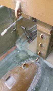
I then spent well over an hour finalizing the wiring for the Trio autopilot’s Autotrim feature. For the autotrim to work it must interface correctly with the TCW Safety Trim box. While I was over in Qatar I worked with the respective gurus, Chuck at Trio & Bob at TCW, to finalize the circuitry for the autotrim. With both of the gurus in coordinated agreement on the wiring scheme 2 years ago, I am just now finally able to implement it. If you look along the upper left edge in the pic below (which is the actual upper forward edge of Triparagon), starting from the bottom you’ll note the DB15 connector housing from the Safety Trim box mounted on the other side of the Triparagon, then a Bridge Rectifier, then a relay marked “RP”. These components make up the Triparagon side of the Autotrim system. Once these interfaces are combined with 2 wires coming from the AP pitch servo and 2 wires coming from the Atkinson pitch trim servo motor, then Voila! … the Trio AP autotrim feature is wired for operations!
Being the social butterfly that I am, I then took the rest of the night off and went to dinner & a movie. When I returned, I pulled the peel ply and checked the 2-ply BID layup on the aft Triparagon mounting tab. Looks good!
Tomorrow I’ll clean up the overhanging glass and excess flox with my Fein saw. I’ll of course redrill the bolt access hole, at which point I should be finished with my Triparagon nutplate mounting hard point installation.