
Today I finished wiring all the components of the Nose Gear Auto Extension Module (AEM) as far as I could without having the physical box in hand. As I’ve mentioned before, the AEM is simply an upgraded replacement of Jack Wilhelmson’s Nose Gear AEX system that utilizes Marc Zeitlin’s design to incorporate a few more parameters into the Auto Extension system to pretty much eliminate annoying false-positive situations and ensure that really the only time the AEX will deploy the gear is on final approach when you actually forgot to put the gear down. To make the magic work, Marc added another airspeed switch (for a total of two), a throttle mounted “microswitch,” and a laser altimeter.
I decided to cram all this new stuff into a box approximately the same size as the original AEX box. Since Marco is 3D printing this one as well, it will have holes ready to go for mounting the internal components and some external mounting flanges for attaching the box to the forward side of F22 with Clickbonds.
The laser altimeter operates on 5 Volts, so it requires a 12V-5V converter. However unlike Marc Z. I chose to mount the converter up front versus the way he did right next to the laser altimeter (which is on the belly near the main gear). There is no right or wrong here regarding the location of the voltage converter, I just simply wanted to drive the weight forward and also hide the converter away in the AEX box.
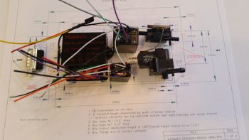
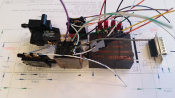
In between the voltage converter (right, below) and the airspeed switches (left, below) are two relays. These relays are unique to my specific system since these are the ones I needed to wire into the mix if I wanted to continue to use my throttle-mounted toggle switch to control the nose gear up/off/dn. These relays are fairly small and light, although robust, so the weight penalty is negligible.
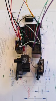
Finally, in each pic I show the 15-pin DSub connector. In the very top pic, and the one below, you can make out the black bar that depicts the hole for this DSub connector on the actual-sized box CAD diagram lying below the components
As with my RCU components, the only thing left to do with these are to physically mount them into the box and then cut & terminate the wires with DSub pins. I do have a few minor tasks that I can complete for the final prep of this system before I have boxes in hand and am ready to install.