
I started out today pulling the peel ply from the ELT mounting bracket base layup. I then cleaned up the layup and drilled access holes for my 4 embedded K1000-6 nutplate assemblies. Finally, I pulled the plastic wrap out of the mounting holes to reveal nice, ready to go screw mount holes.
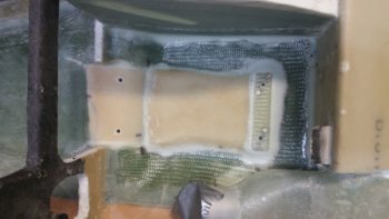
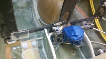
I then did a test install of the ELT mounting bracket. All was good except at the front, where the existing floor of the fuselage slanting forward up to, and including, the bottom panel bulkhead lip (the stuff that I cut out to make the ELT sit flat) was physically too close to the mounting bracket and was keeping the mounting clip from getting inserted onto the latch hook.
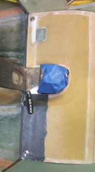
It took me 3 rounds of cutting, grinding and sanding to finally get it dialed in just enough where I could get the upper latch ring down over the lower latch hook. With that action, my ELT mounting base is officially installed!
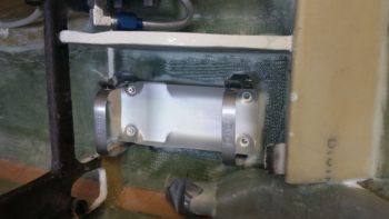
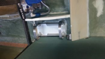
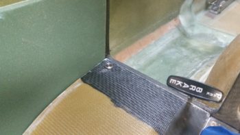
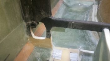
I took a quick shot showing the clearance to the left of the ELT mounting base with the left armrest console sidewall.
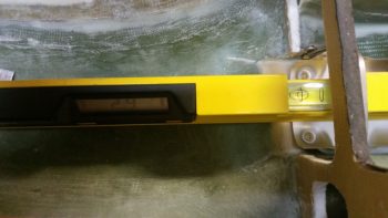
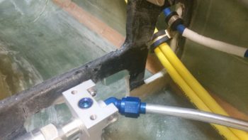
I then grabbed my digital level and tested the angle of the ELT mounting base: only 2.9° nose high… I’ll take it!
With ELT mounting bracket “sideline project” out of the way, I started on the final task #3 of my 1-2-3 task list that I ginned up early last week for getting the pilot seat thigh support finished. In my mind this 3 item list was going to take 2 days . . . and here we are almost a week later!
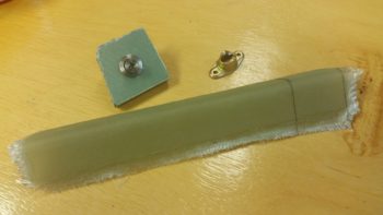
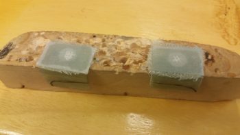
Anyway, task item #3 is getting a CAMLOC installed in each forward corner of the thigh support top/cover plate (or “floor” as it’s called in the plans). I rounded up a 3/8″ thick piece of foam that was glassed both sides to mimic my thigh support cover. I also rounded up the 7-ply glass bracket stock I had made up this past weekend.
I marked the bracket stock to cut out a bracket for the CAMLOC receptacle, which I only have one for testing purposes at this point [NOTE: All my other “CAMLOC” receptacles for the engine cowlings are the SkyBolt variable adjustable type].
I then trimmed the bracket stock and lopped me off a nice bracket from it.
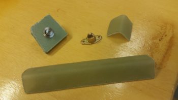
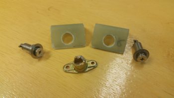
A bit later, here’s my 2 CAMLOC brackets for the pilot seat thigh support, with holes drilled for the receptacles. As you can see I also grabbed another stud and grommet, which I’m also testing to determine my preference.
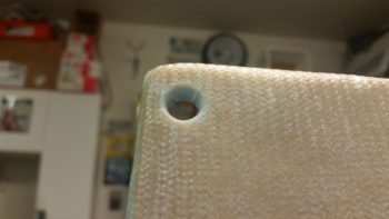
I then drilled the stud/grommet thru-holes both left & right in the forward corners of the thigh support cover plate.
Here’s a shot with both stud/grommets in place on the thigh support cover.
I then did some multi-faceted layups. I started by slathering flocro in the thigh support corner stud/grommet thru-holes (after I prepped the holes by digging out the foam around each hole). I worked the flocro in nice and good so that it was set inside & past the edges of each hole.
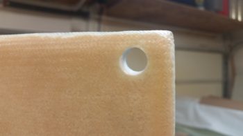
A few hours later I redrilled the thigh support corner stud/grommet thru-holes for nice strong holes with very clean edges.
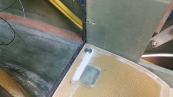
I needed some more surface area for my thigh support CAMLOC receptacle brackets to mount to, so as part of my multi-faceted layups I used some flocro to mount a couple ~5/16″ thick foam pieces (that I previously shaped) into the upper outboard corners of each of the panel bulkhead’s “map pockets”. I then glassed patches of BID –2 plies front, 1 ply aft– over these newly inserted corner pieces.
I then peel plied the layups and left them to cure.
A number of hours later I pulled the peel ply and razor trimmed the freshly glassed CAMLOC receptacle brackets’ backplate mounting extensions.
The last bit of glassing I did on the days’ big layup-palooza was to added 2 plies of BID to the top of each thigh support CAMLOC receptacle bracket. I noted when the CAMLOCs where in the closed/fastened/locked position, that the stud was just slightly proud of the grommet. I figured 2 plies would get me acceptably closer to a flush stud inside the grommet. Plus I’ll have paint on the thigh support cover, so I should be able to dial in the depth of the stud to match the grommet on each side.
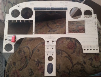
With my shop work complete for this evening, I then spent over 2 hours working on my mockup/test instrument panel. I drilled out & jig sawed the 8 holes above the HXr EFIS (PFD) for the Korry status lights, and then another 6 holes above the GNS480 GPS unit for the external GPS annunciator lights (also Korry).
I then spent a good amount of time figuring out where the remaining panel components, mainly switches, will go.
Tomorrow I hope to finish up the pilot seat thigh support CAMLOC install and the instrument panel mockup configuration. For the panel I’ll probably construct a behind-the-panel cross bracket to mimic the F28 bulkhead so that I can install the Triparagon on the panel mounting base.