
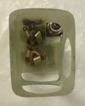
Today I started out by cleaning up the 2 small layups that overlap onto the two internal sides of the PTT 1/4″ phenolic mount and the foam/flocro recessed PTT button housing junctions.
I then identified my desired positions for the headset jacks and drilled the two 3/8″ holes for those. I then of course installed the jacks to ensure they fit . . . which they did (yeah!).
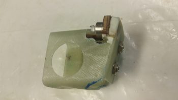
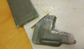
So, here’s the forward Left GIB mounting/PTT button/headseat jacks bracket that will reside on the front face of the left GIB armrest.
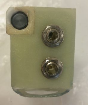
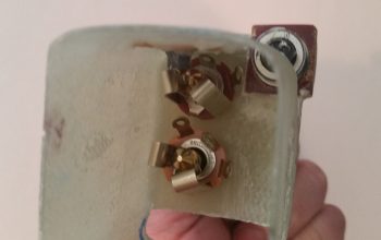
Here’s the business end showing the internal side of the bracket. Yes, it’s a bit tight in there, but it all fits fine.
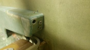
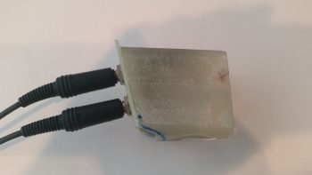
And here’s an “action shot” showing the armrest front faceplate set in place. I still have just a bit of cleanup work to do to get it all squared away cosmetically, but structurally –beyond actually installing it to the sidewall– I’m done.
To verify that there were no clearance issues with the headset plugs, I took the bracket assembly upstairs and hooked up one of my headsets. Looks good!
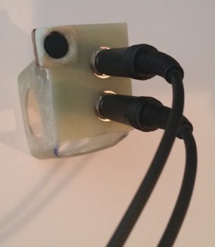
Here’s close to the actual angle that the GIB will experience when plugging in their headset.
And from the other side.
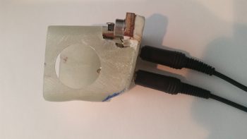
The internal clearance with the plugs installed is fine as well.
I then set my sites on knocking out the lower cross connect duct that comes out of the oil heat exchanger and transits the hot air into the ductwork. I played around for quite a while to figure out the exact duct size, especially since it was a variable along with the height of the heat exchanger off the cockpit floor.
Ok, my “standard” ducts are 3/4″ wide x 2″ high, which provides a close approximation air volume wise as 1.5″ round SCAT tubing. The optimal height of my heat exchanger off the floor is 0.9″ (vs. 2″ high), so I clearly had some hard configuring to do.
Since the heat exchanger sits over (actually “adjacent to”) the existing ductwork that I just created –with the majority of it being over (again, “over” as in covering) the horizontal air feed to the GIB– I decided to use the area UNDER the horizontal air feed that is just outboard & to the left of the heat exchanger for a wider/flatter duct, thus letting me reclaim the approximate amount of volume lost by having to shorten my duct to 0.9″ (vs. 2″ high).
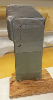
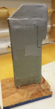
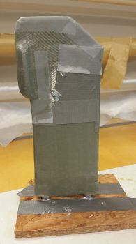
Thus, in the first pic below, you’ll see what looks like the goiter-type protrusion that sticks out on the bottom of large ocean-going vessels. This is the widened horizontal segment of the lower heat exchanger duct, which then makes a 90° turn upwards along the forward edge of the heat exchanger until it empties out into the ductwork (near the angled part).
Additionally, the angled corner you see in the pics below is actually the intersection of the heat exchanger outlet duct where it meets the pilot seat back (NOTE: In the pics below, the heat exchanger is mounted into the board with the aft edge down).
I then laid up a bunch of UNI scraps as the first ply of glass and then laid up a ply of BID over that. I peel plied a bunch of the edges and then took off to have dinner with a buddy of mine.
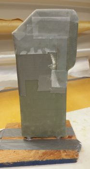
Upon my return from dinner, with the glass at a perfect “green state,” I cut the short edge and the slanted corner glass right down the middle. I then slowly worked the rather pliable glass off the heat exchanger and then did my best to ensure all the glass was sitting exactly how it was while it was on the heat exchanger… so it would be correctly shaped when cured.
Obviously, my other option was to let it cure on the heat exchanger, Fein saw it off in 2 halves, then glass the halves back together. Not only did I want to avoid the weight, glass usage, and hassle & time of another layup, I didn’t want to accidentally cut into the heat exchanger cover that was just a scant couple of duct tape plies from the glass I was cutting.
Tomorrow I’ll shape & glass the upper heat exchanger inlet duct, as well as trim up the outlet duct I glassed tonight. In addition, I’ve realized that I need to get at least the aft oil heat lines installed before I install the forward Left GIB mounting bracket (for clearance). So tomorrow not only will I build a couple of oil hoses, but I’ll also start work on mounting the oil heat pump.