
I actually spent quite a few hours today building a lower cowling dolly that you’ll see in a number of the pics below. I saw one of these in Walter’s hangar as we were helping remove the wings off of his Long-EZ and thought it was a good idea. Well, although I got the dimensions from Marco, they didn’t translate over for whatever reason to my cowling and build dimensions (possibly since my fuselage isn’t loaded all the way down?). I still used it to a degree, but I will have to mod it much further for it to really be helpful.
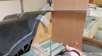
My goal today was to mock up the lower cowling in its close to final position (as best possible) to check the clearance between it and the engine air induction system… specifically the fuel injection servo. To better ascertain the position of the lower cowling, I went ahead and set the top cowling in place, which I was going to do in short order anyway.
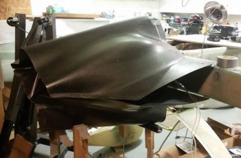
I then used duck tape to help wrangle the 2 cowling halves into some semblance of order. I’m definitely happy with the fit of the cowlings, and although Mike Melvill had an IO-360 inside of them, trust me, they are still a close fit to an IO-320 sized engine.
I taped the cowling at the top cowling-firewall interface, and was glad to confirm I have a good firewall fit, with the shape of it matching the cowling shape.
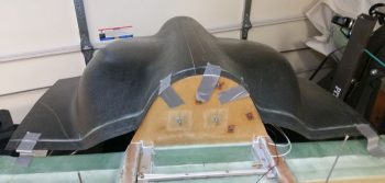
Since I had the top cowling close to its final position (I double-checked the plans, my notes, other builders’, etc. to ensure I had it close to where it needed to be…) I then made some templates to use for the cowling angle interface with the canopy and D-deck/ turtledeck assembly.
Here’s another view of my canopy-top cowling interface angle template. Clearly I will most likely need to throw a curve into the mix as I mount the canopy, but it gives me a good starting point.
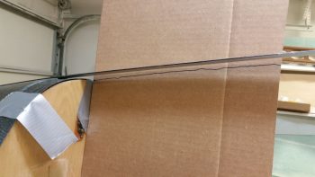
I also drew hash lines on the longerons and marked the extended angle of the top cowling contour about 18″ forward of the firewall.
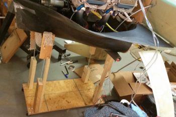
Here’s my version of the lower cowling dolly. Mine needed to be much wider front to back and much taller than the one that Walter built for his airplane.
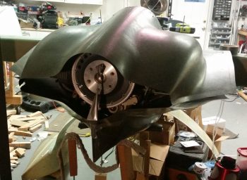
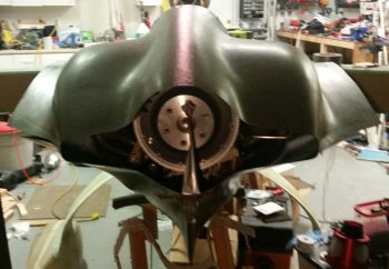
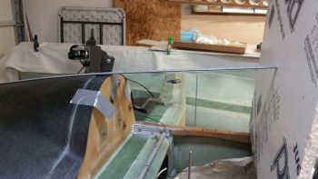
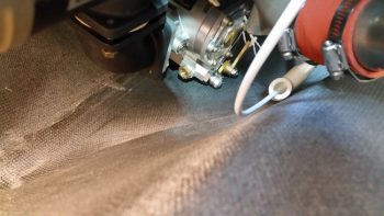
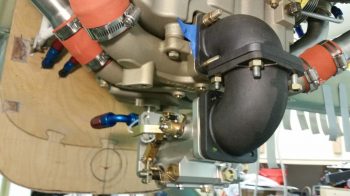
As you can see, I removed the top cowling to better check the clearance between the bottom cowling floor and the fuel injection servo.
Here’s the best shot I could get of the fuel injection servo position inside the lower cowling. It may be hard to tell, but in this configuration there is NO clearance and the cowling is actually just touching the fuel injection servo. In fact, the very bottom nub sticking out to the right on the servo is the main fuel feed line attach fitting… clearly no room even to connect the fuel feed hose!
Very frustrated and perplexed on my no-clearance issue with my lower cowling, I took a break and grabbed something to eat. After about an hour, with the worst case scenario of having to extend a trough under the lower cowling in my mind, I went back down to the shop to assess the clearance issue.
As I was literally sitting under the engine just looking at the layout, I came up with a very viable solution.
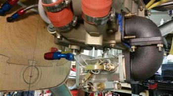
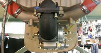
You see, my paradigm was that the main fuel line was coming in from the right side, and the hose coming in from the fuel distribution spider on the top of the engine was from the left. No need to change any of that, but I did need to rethink the one thing that was really causing my clearance issues: the -4 AN 90° fitting on the top of the fuel injection servo. I had it pointed to the left as I lamented the lack of clearance between it and the bottom of the oil sump . . .
But if I moved the servo about 1/2″ forward (which I could do since I had spacers installed in between the elbows), not only did it push it forward to where the cowling was lower, but if I faced the top fitting to the RIGHT then it put the fitting right into a V-shaped channel on the bottom of the Superior cold air induction oil sump. This allowed clearance to get the hose end fitting onto the servo outlet fitting! Yes, I would have to spend another $20+ on yet another hose end fitting, but by doing this configuration change it gave me 2 options: A) Run the fuel distro spider hose above the fuel injection servo and in front of the air duct elbows with a 150° U-turn hose end fitting, or B) Run the fuel distro spider hose aft of the air duct elbows with a 90° hose end fitting (I’ll admit that to acquire the best solution here I bought both fittings…).
I’ll have to assess this when I get the fittings in and test these fuel line runs. This leaves the right side main fuel feed line unaffected and it will still attach to the fuel injection servo on the right side (low).
The resulting change in my configuration will require only about a 3/16″ phenolic spacer between the lower 85° elbow and the fuel injection servo. I will also have to replace the threaded studs on the cold air induction plenum for connecting the upper elbow to the plenum (at a minimum the lower studs, since it is virtually impossible to get a nut with so many washers on them with the current configuration).
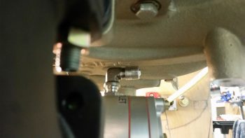
In figuring out the final install point and configuration of the RAM air canister (not pictured here) I needed to install the 1/2″ NPT elbow on the bottom of the oil sump to assess how to route the hose from the sump to the firewall…. around the RAM air canister. I tested a 90° hose end elbow (blue & red) but think a straight hose end may work as well. However, since the oil heat feed line from the sump looks like it will enter the firewall on the lower left side, this will require the associated hell hole oil line to crossover from the right side oil pump fitting over to the lower forward left side of the firewall (again, crossover in the hell hole). Not a big deal, but I will have to avoid and go above the RAM air intake expansion chamber ( . . . never-ending ripple affects!).
The bottom line is that it looks like all the components should fit, but the clearances from one component to the next are all AMAZINGLY CLOSE (but, I will note not too close to allow vibration to cause issues).
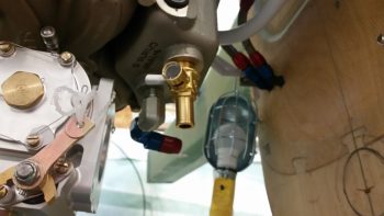
Here we have the oil drain valve with the oil heat feed 90° fitting just behind it (pic from right side of engine).
I’m fairly confident that this configuration will give me just enough of the clearance I need below the fuel injection servo and allow for all the critical air induction and underside oil sump fittings to play nicely with each other.
Of course I will have to also rotate both the fuel injection servo’s throttle and mixture levers to avoid hitting the lower cowling (I planned out the mods on those a few days ago), but again, I don’t foresee any issues with those as well.
I think with these sideline tasks taking a bit more time than I expected, my timeline for getting the engine back off the firewall and onto its stand will have to slip a day or two. Tomorrow I should be close to finishing up the firewall configuration tasks and pulling any more data I need to from the engine being mounted.