
Chapter 23 – Engine, Prop, Components & Cowlings
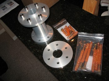
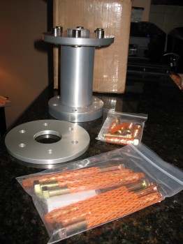
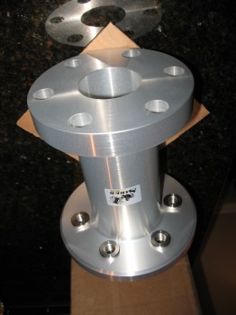
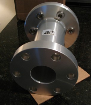
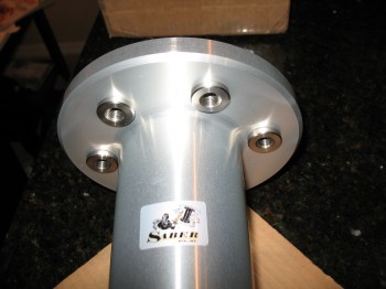
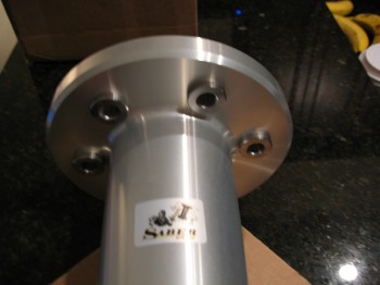
March 2013 — I’ve been focusing some on the engine & figuring out the components I need. I had put an order in with Sam Tillman at Saber Manufacturing for an 8-inch prop extension. Sam of course does some amazingly high quality work. Very nice.

Another serendipitous find I made was a local manufacturer that makes certified parts for military aircraft simulators. I guess because it was the holiday season, and since my buddy Marco wanted one as well, I was able to talk them into doing a two-unit production of some F-16 throttle handles. Since instrument panel space is limited in a Long-EZ, I want to put a number of switches on my throttle handle along with my grip stick to attain the highest level of HOTAS (Hands-on-Throttle-and-Stick) as possible (I listed the throttle as Chapter 23 since it’s actually not covered in the Section I plans, but rather in the Section IIL plans which covers engine installation exclusively).


[OPERATIONAL NOTE: Due to a better fit and the convenience of pre-installed military grade switches, I will be using the right side half of an F-15 throttle handle vs this F-16 throttle handle. See Chapters 16 & 22 for more info.]
•••
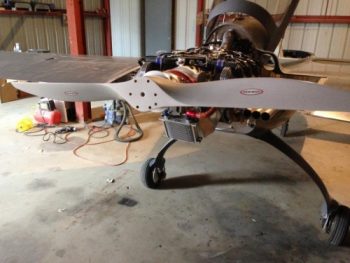
12 April 2013 — Today I got to see & touch a real ECi IOX-340S engine at SNF 2013! This will be how mine will look in general.
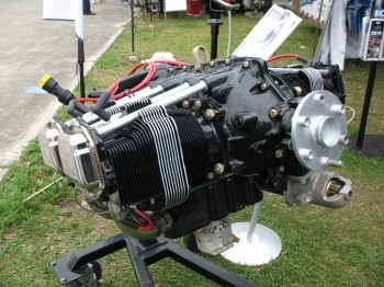
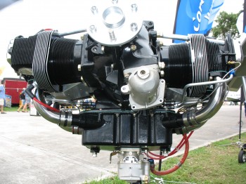
Below you can see ECI’s cold air induction system on I believe an IOX-360. Notice on the IOX-340 above they have have the normal oil sump without cold air induction.
•••
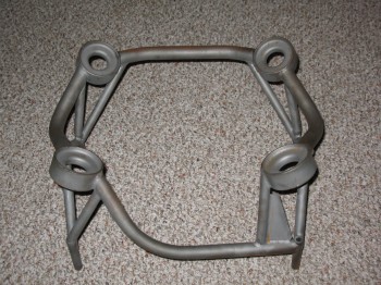
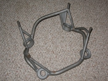
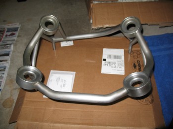
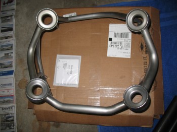
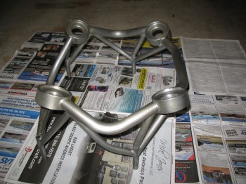
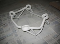
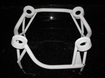
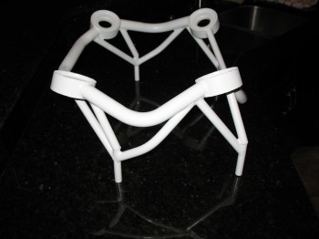
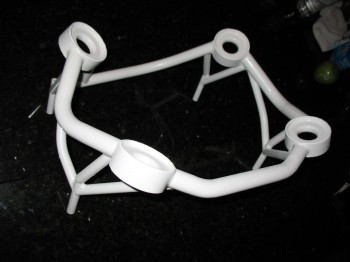
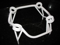
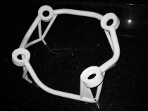
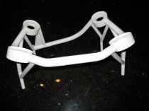
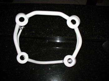
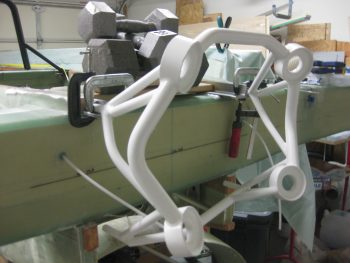
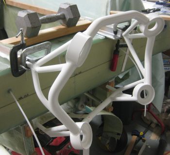
13 April 2013 — I found Randi & Chrissi of Cozy Girrrl fame today to pick up my engine mount that I had ordered from them last month. Looks good. I think the humidity and the amount of time between it getting built and me picking it up allowed some surface rust to form a bit. No worries, I’ll knock that off and paint it so it will stay corrosion free until I use it. It’s amazing how small all the different components seem for the Long-EZ, but this sucker is stout and definitely well made!
•••
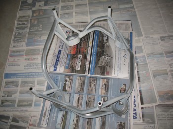
18 April 2013 — Tonight I finally rolled up my sleeves, grabbed a can of WD-40 rust remover, my disposal econo-pack of wire brushes from Harbor Freight and went to work on removing the surface rust from my engine mount (and making sure it stayed gone!).
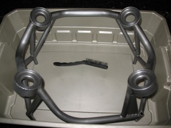
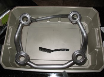
I grabbed some Simple Green and washed the engine mount thoroughly three times, drying it in between each wash to ensure all of the WD-40 Rust Remover was removed.
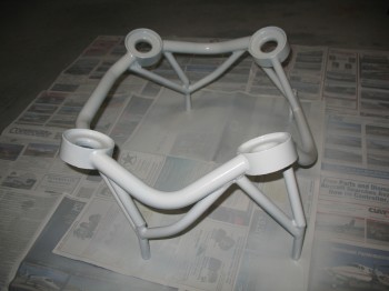
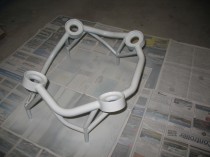
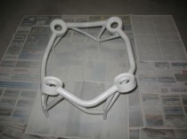
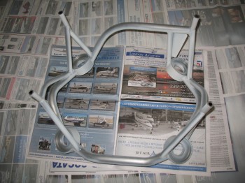
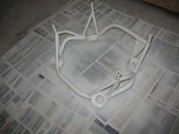
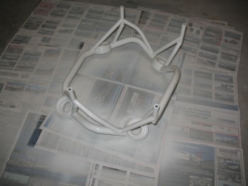
Once I got the engine mount completely doused with paint, I let it dry overnight in the garage before I brought it upstairs. (Note: This was just a quick paint job to keep the mount from any significant corrosion in the near term. I will most likely have it bead blasted, then prime and paint it on a stand to ensure there no areas with stuck newspaper or floor dust attached to it).
 •••
•••
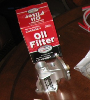
23 April 2013 — Today I received B&C’s 90° Oil Filter Adapter kit. The ECi IOX-340s does come with a 90° oil filter adapter as a standard feature (if you want to buy it), but their’s is made from cast steel and just isn’t as nice as the machined aluminum one from B&C. Normally I don’t go for form over “function,” but in this case I went with the far superior one, not just the one that would do the job (If I remember correctly, the B&C adapter is lighter, so I’ll go with that as a justification for it!).
 •••
•••
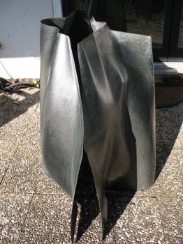
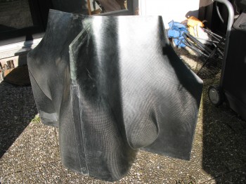
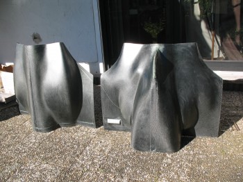
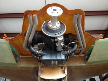
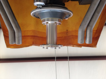
16 June 2013 — I took a moment while I was cleaning & organizing everything to pull my top & bottom engine cowlings out to take a look at them. These Carbon Fiber cowlings came off the same molds that were from Mike Melvill’s cowling halves, used as the original plugs.
This story is all detailed in the Canard Pusher newsletters (#’s 86 & 93), but in short before Mike set out on his around-the-world trip in 1997 with Dick Rutan, he wanted to solve the ever-present high engine & oil temps that had plagued his Long-EZ from day one. After talking with Berkut designer, Dave Ronneberg, Mike decided to try the Berkut-style armpit coolers. He was so impressed with the cooling that he designed a new cowling incorporating the new armpit inlets. Since he was manufacturing a whole new cowling, he decided to make it out of Carbon Fiber, which drastically reduced the weight, halving it from 26 lbs. down to just 13 lbs. He handed the forms over to Larry & Mike at Feather Light who now make & sell the carbon fiber cowling.
One thing to note (which I did not until I played around with the cowling) is that Mike Melvill had a NACA scoop inlet for his engine which he simply filled in and glassed over when creating the new cowling. The NACA scoop was built 4 inches below the bottom of the original firewall, thus the new bottom cowling hangs down 4 inches lower than a stock firewall.

•••
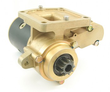
30 July 2013 — Besides starting to pick up the main parts of the engine, in July I also started down that long road of picking up all the engine accessories as well. There were a few components that I still wanted to do a fair amount more research on, to be sure I was getting what I felt was the best fit for my engine and airplane. Of course I read a ton & made quite a few phone calls to some really smart folks.
One thing that I new for certain was that I was going with a B&C starter. While B&C starters ARE NOT the lightest starter you can get out there (by a few pounds), from every bit of feedback I could garner these guys are bulletproof. Thus, a B&C starter was the first engine accessory that I pulled the trigger on (example pic here).
•••
8 August 2013 — Today I ordered a set of 4 ECi Tapered-finned Nickel+Carbide Cylinder Assemblies for my IOX-340S engine. The set also includes 9.5:1 compression pistons. Since I picked up the engine case, the crankshaft & camshaft a few weeks ago, I’ll start purchasing the accessories over the next year so that when I get back I can put this thing together with Tom Schwietz.
A nice thing about buying the cylinder assemblies as a set is that ECi ensures that all the cylinders are flow matched, making for a much smoother and efficient engine.
Here’s a representative pic for context.
•••
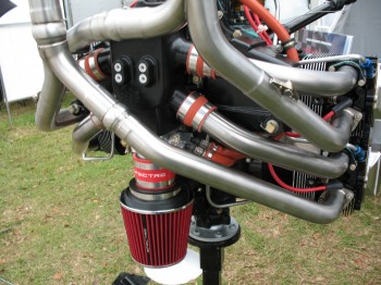
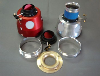
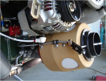
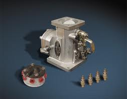
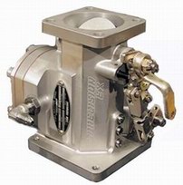
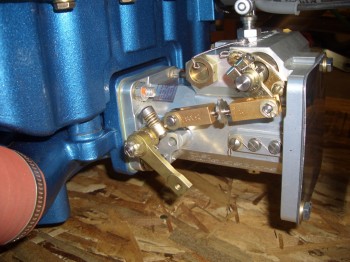
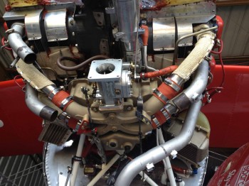
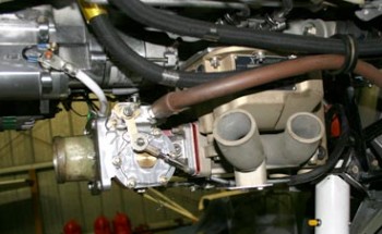
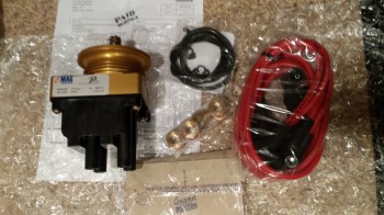
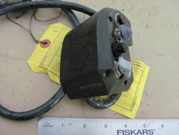
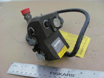
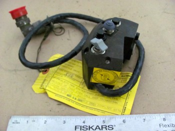
8 September 2013 — In early September I went with a one-off type component: Rod Bower’s Ram Air System. Normally Rod works with the RV gang, but I spoke with him at length about using this on a Long-EZ, and I think this is the polished, albeit more sexy version of what James Redmon built (himself!) for his Berkut. And since James’ Berkut is literally one of the nicest canards in the world, I gotta have something nicer than him! Ha!
If I haven’t explained it previously, a Ram Air system is fairly straightforward in operation and does what it’s named: It simply takes an external, isolated source of air and rams it into the intake manifold via the fuel injector servo WITHOUT being filtered. Yes, I did say it’s UNFILTERED AIR being RAMMED into the engine intake.
“Ok, is that smart?” you ask. Of course not! At least not on the ground! Ahhh, so the beauty of Rod’s system is that you throw a lever (or a servo switch) and a butterfly valve closes off the outside air source. The air, then, is brought in through the 4 reed valves on the side of the aluminum coffee-can sized housing that just so happens to have a K&N filter therewith inside. Thus, on the ground, or close to it, the air is in fact filtered. Bit once airborne, the valve is opened to let the ram air do its magic, ala Red Bull Racers, thereby providing anywhere from about 1–1.5 inch gain in manifold pressure. Brilliant!
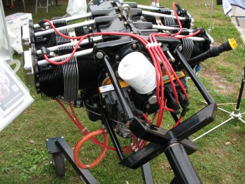
And here’s what it looks like in kit form & installed on a tractor setup::
•••
4 October 2013 — Well, I understand that I’ve pretty much gotten into the same mode that I was in Tampa, in that I’m merely laundry listing out all the components that I’m allocating for the build. But trust me, I’d much rather be reporting on progress being made on the actual build. Here in the near future, as I get closer to finalizing my electrical system, I will try to find a way to transfer it from CAD into maybe a PDF format to post on the site.
Being deployed for a year has given me quite a bit of time to hash & re-hash my component choices ad nauseum. I’ve been able cross check my decisions, talk to some real gurus and hear & read arguments both for & against various parts & components.
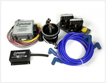
My latest final decision was what electronic ignition system I was going to go with. I’ve had reports from a number of friends & builders, and scoured the forums to finally come to my decision. I also spent hours at each booth during SNF13 to figure this out. In fact, before they closed their doors, I had spent a fair amount of time on the phone with the guys at Mattituck Engines discussing electronic ignition systems for experimental engines. My final decision for my ignition system is an Electroair on one side paired with a Slick magneto on the other.
And although it may sound silly or incompatible to some, after a discussion with a few engine gurus I’m holding out the option (and will research) in the future to replace the Slick mag with a PMag.
•••
21 October 2013 — Well, an alternator is difficult to classify as belonging to ONLY the Electrical System (Chap 22) or the Engine (Chap 23), so I labeled it here as belonging to both categories.
I’ve held off for quite some time in buying my alternator, which is B&C as well, simply because I didn’t feel I had identified the avionics and electrical components within the electrical system to the degree necessary to know what size alternator I would need. B&C offers both a 40 Amp and a 60 Amp externally regulated alternator. Of course an ever-present concern of mine is weight, and at the very aft end of the engine, the 2.4 pound difference (6.1 vs 8.5) between these two alternators clearly has a decent affect on the aircraft’s weight & balance at such a rearward arm. With technology allowing me to have a lighter battery up front (15 pounds vs the traditional ‘old school’ 25 pounds), even with an extended nose I’m trying to keep the hind end of my bird light. Especially considering I’ve dumped an O-320-sized engine back there when the Long-EZ was pretty much (Read: “specifically”) designed for the lighter O-235 engine.
Have I made my case? Quite a bit of yammering over just 2-1/2 pounds, eh?! Sure, weight is evil! (I wonder if Burt would be proud of me right now . . . )
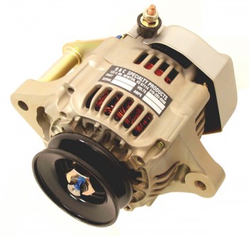
And so it is mis amigos, that I was comfortable enough in my electrical system load analysis at this point in time that I pulled the trigger on the B&C L40 40 Amp alternator below. Also, as a data point, my main bus with all the components I have listed in my electrical system will have a steady current draw somewhere around 22 amps. Not bad for a full up IFR glass panel with autopilot.
As per usual, here is a representative picture from the B&C website.
•••
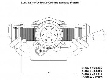
5 November 2013 — Today I pulled the trigger on my exhaust system. The exhaust had been a huge question mark on my list of things to do for a very long time. Luckily, a quick email to Long-EZ Buildmaster Mike Beasley quickly cleared up any questions I had on Long-EZ exhaust systems. He quickly referred me to a Long-EZ exhaust system guru, Clinton Anderson, from Custom Aircraft Parts in El Cajon, California.
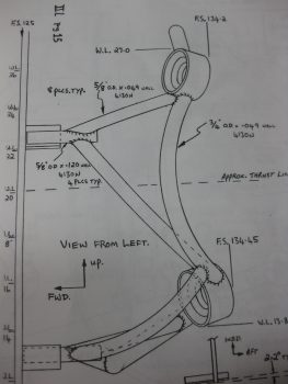
Clinton and I discussed the exact type of exhaust I needed for my IOX-340S. It came out to be fairly simple, since it’s the same exact exhaust system used on an I/O-320. Below is the initial technical drawing he sent me.
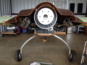
And here are some pics of these exhaust pipes on Mike Beasley’s fantastic Long-EZ build:
•••
10 December 2013 — Well, today’s purchase wasn’t the most expensive component I’ve bought for this airplane, but it’s up there.
But before I get into today’s bank account hemorrhaging, let me recount my engine saga: The original engine that I had decided on was a Mattituck TMX IO-320. I had worked fairly extensively with Mike Yousik from Mattituck to figure out the configuration of my future engine. In the late summer of 2012, I made a phone call to Mattituck to get some info on the TMX IO-320. It was then that I had learned that Mattituck Engines had gone out of business. So why I am recounting such a seemingly sad tale? (Which it isn’t by the way… I’m very happy to have gone the ECi builder’s assist route!)
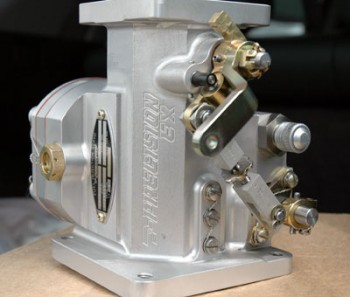
Well, the significance of my Mattituck TMX IO-320 “no more” story is that I had already extensively researched the fuel injection servo that Mattituck used on their TMX series engines: The Silver Hawk EX.
One key feature that the Silver Hawk EX fuel injection system has is that it does not require a fuel return line. Now, I know a lot of folks will balk at such a crazy notion that a fuel injection system does not require a return line to the tank. The Airflow Performance (AFP) system uses it! I know, and I accept the fact that I am flirting with near certain death due to my return-less fuel injection system.
Ok, all snarkiness aside, as I mentioned before, I did A LOT of research on this long before I pulled the trigger on this system. [BTW, Aircraft Spruce hornswoggled me as well by offering a pretty good holiday sale as well! Also bastards!]
I had talked with engine manufacturers, engine shops, builders (read: Vance Atkinson) and of course the makers of the Silver Hawk system, Precision Airmotive, at Sun ‘n Fun. And of course I can’t forget the myriad of feedback I read on this system on the Van’s forums…. overwhelmingly positive.
So essentially every bit of my research and all the planning I had done up to the point of learning that Mattituck Engines had gone out of business was predicated on the constant that a Silver Hawk fuel injection servo would be used on my engine. Since I liked the features of the this fuel injection system, I uncharacteristically just picked it so that I could move on to other important decision points I need to made for this project.
Another BTW: I am in no way slamming AFP–I think they have a fantastic product and I might have just as easily have gone with them if I wasn’t already sold on the features of the Silver Hawk system.
•••
24 December 2013 — Hello again folks. Today I shall discuss Oil Coolers! So, as per usual I’ve taken my historical data on oil coolers, reviewed all of it, then went hunting for more data. I think I’ve failed to state that a fair amount of my research is via Kitplanes magazine as well, and as a lot of you know they’ve had a couple of good articles on oil coolers lately. Also, I know I mention the RV forum a lot, but don’t get me wrong, I’d be remiss to neglect to say that I do check out the Canard Aviation Forums pert near every time as well. Finally, don’t get me wrong by thinking that any of the forums are the final say in selection of my aircraft components (ok, unless it’s Marc Z!). I spend a fair amount of time (much to their chagrin I think at times) talking to builders (canards & engines), EZ flyers, the actual parts manufacturer bubbas, and of course my Long-EZ building buddies.
Thus, for my oil cooler I reached out to one of those fellow Canardians, Mike Beasley, to asked him his thoughts on oil coolers. He came back with the recommendation by EJ Johnson & Co. to go with a Stewart Warner (now Meggitt) cooler and I wouldn’t be dissatisfied. He said if I bought any other brand, I would probably come back to Stewart Warner, on my knees, begging for forgiveness, asking to be given one more chance to use them because I clearly wasn’t thinking right when I bought brand X. So what did I do? (Remember, I’ve never claimed to be that bright!). I bought brand X… literally! Sorry Mike… good advice, but remember, I’m cheap!
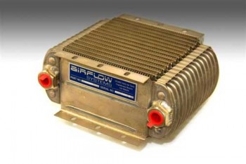
So after some back and forth discussions with Wayne Thomas from Pacific Oil Coolers and Bill Genevro from Airflow Systems (both incredibly helpful), I decided to go with an Airflow Systems Series-X 2008X. If you know this line of coolers, you know that it’s about the biggest one they make. So why did I order this mo-jamma? Well, remember, not only is a Long-EZ obviously a pusher–with the inherent cooling problems that brings to the table right there–but I’m running a strokered engine with tapered cylinders, high compression pistons, Nickle+Carbide cylinder walls (much better rust resistance, but runs a little hotter usually), fuel injection, and cold air induction with RAM air intake. All these are significant heat producers, so I need as much oil cooling realistically as I can get. Of course figuring out engine & oil cooling is always a crap shoot… hard to engineer, typically harder to predict, so I’m trying to stack the deck and HOPEFULLY get the odds in my favor just a bit!
My Christmas present to myself: an oil cooler (hoo-ah!).
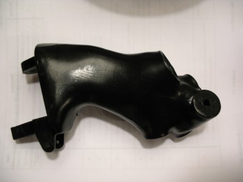
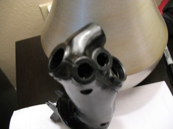
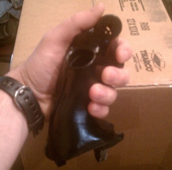
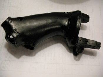
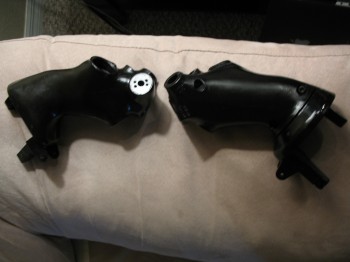
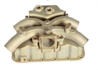
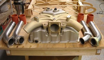
3 March 2014 — Today I sent a check off to my engine builder, Tom Schwietz, at Aero Engines for a Superior Cold Air Induction Sump Kit. I have been doing a ton of research on my cold air induction system over the past few weeks, and finally decided to go with Superior over the Sky Dynamics cold air induction system.
Why Superior? Cost and size. Ok, there’s no doubt, in my mind at least, that Sky Dynamics’ cold air sump is the best cold air sump for a Lycoming that money can buy. This makes sense, since the Red Bull Air Racing team uses this system on their race planes. But although the Sky Dynamics is the best that money can buy (again, my opinion), it takes a whole lot more money to acquire this system than it does the Superior cold air system. The Superior system works well enough for what I need it to (more on that below) and is about $2000 cheaper, which of course is money that can be used to acquire other cool airplane stuff. Also, even though Superior is about 3 lbs heavier than the Sky Dynamics, it is still about 6-7 lbs lighter than the original Lycoming vertical oil sump.
Now, why not ECi’s cold air induction? ECi makes a great, lightweight magnesium cold air induction sump, but the two main issues with the ECi have to do with shape and configuration. First, the shape of the oil sump is much like the original Lycoming cold air induction sump in that it has “wings” that stick out on both the right & left side of the oil sump. These “wings” probably aren’t an issue in a normal downdraft cooled tractor airplane like an RV or Glastar, but for an updraft cooled pusher I want as much unimpeded airflow up through the cylinders as possible. Unfortunately, ECi’s oil sump “wings” sit in the path of cylinder cooling airflow. Next, the configuration of the cold air plenum sits farther forward on a tractor configuration than both the Sky Dynamics and Superior cold air sumps. On a pusher canard, this of course means the cold air intake plenum, and thus the fuel injection servo, are situated farther aft… and in such a tight cowling as on the Long-EZ, space is a premium. Especially when I’m going to have to do a near 180° U-turn on my intake ducting to bring air into the rear-facing fuel injection servo. So above are the primary reasons that I eliminated ECi from consideration.
As for the positioning of the fuel injection servo as it’s mounted to the cold air plenum, the Superior has the best (farthest forward in a pusher configuration) of the cold air induction systems I assessed. As you can see in the pics below, on the Superior the fuel injection servo is pretty much mounted in line parallel with the aft edge of the oil sump, unlike either the ECi or Sky Dynamics sumps. As I mentioned above, this provides more room in the aft end of the cowling for not only routing the intake air duct, but clearance between the fuel injection servo and both the alternator and starter.
Now the intake plenum on the Superior is significantly smaller than both the ECi and Sky Dynamics plenums, but still, the reviews on the Superior Cold Air Sump are pretty darn good.
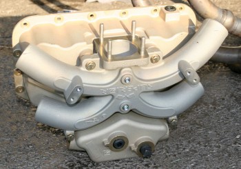
One other distinguishing feature on the Superior sump is the robustness of the fuel injection servo mount. The Sky Dynamics requires extra mounting brackets to secure the servo since the cantilevered weight of the servo would prove too much for the mounting interface.
Finally, after reading some discussions on the advantages of cold air induction–or lack thereof–from R. Mahlon and Rod Bower, I seriously considered giving up my goal on cold air induction and simply go with the standard Lycoming vertical oil sump. The problem with a regular oil sump though is weight. Going with a cold air induction sump actually serves to save a good amount of weight, if nothing else. Moreover, the normally accepted value for increase in horsepower using cold air induction vs a vertical oil sump is 5-7 HP. If I can gain even half of that while saving weight, I’ll still be happy with the system.
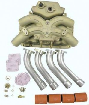
[Note: None of the pics above are of my particular set-up, but merely included as representative of the Superior cold air sump system]
•••
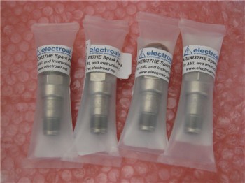
20 March 2014 — Gina, my ever-diligent epoxy mixer, gave me a set of Electroair spark plugs for my Birthday. Now that’s a girl who knows what a guy likes!
Here are the Tempest spark plugs used specifically with Electroair’s Electronic Ignition system.
•••
12 May 2014 — In creating my Electroair Electronic Ignition wiring diagram and digging down into the weeds of it all, I kept coming across an issue that on the surface might not seem that difficult to fix. And honestly, perhaps it’s not for some folks.
So let me give a little background. For my ignition system I had planned to install an Electroair electronic ignition system in lieu of one Slick magneto on one side, but still go with a Slick magneto on the other side. I had talked at length with Kevin at Sky Dynamics and few other engine gurus on simply replacing the Slick mag with a P-MAG when that dreaded “500” hour mag overhaul came due. They understood the economy of using what was available and cheaper in the near term, but going with a much better solution in the long run. In short, the feedback was that it wasn’t a bad plan.
This ignition configuration then became my plan for quite a while. However, in my recent focus on this system, I’ve run across a couple of things threw a wrench into my planning process. The final result though, is a more optimized install and system anyway, IMO.
First, after talking to a couple builders and reading a few accounts of swapping a magneto out for a P-MAG, or any other electronic ignition, probably made my statement, “Oh, I’ll just swap out the mag for a P-MAG” maybe just a bit too simplistic. Can it be done? Certainly. And of course it’s not an insurmountable job. The problem though really comes down to space & access. There is simply not a whole lot of room between the engine accessory case & the firewall in an EZ. Again, it doesn’t place the swap-out in the realm of the impossible, I’ve just heard (most recently from my buddy Dave Berenholtz) that it’s a real PITA! And I don’t know about you, but I try to avoid PITA situations as often as possible!
Second, I had planned on using the Slick mag side of my ignition to start the engine, then flip the Electroair EI ON once the engine was going. The issue here becomes a little multi-faceted. Slick mags of course come in two flavors: Impulse & Non-impulse. Impulse mags are used to start the engine, while non-impulse mags are used as just a redundant ignition system to get juice to the spark plugs. In an attempt to make my future P-MAG install as painless and pre-readied as possible, I would need to use a non-impulse mag in order to NOT have to pull the impulse mag innards and also still be able to reuse the non-impulse drive gear (‘cuz it costs a bit). Well, in order to use a non-impulse mag, I would need to use the Electroair EI side to start the engine. No problem, the Electroair EI works great and can be used as the engine starting ignition if that’s how I wanted to configure my ignition system.
While researching the feasibility of using the Electroair as the starting ignition, and how to do it, I ran across a potential issue. Apparently, some Electroair users have had starting issues when the bus voltage is too low, caused by anything from a battery issue to cold weather. Moreover, these issues were popping up (NOT in overwhelming numbers mind you) in RVs and Glastars, not just canards. In my mind, with such a long power run between the battery in the nose and starter/EI at the tail end that we have in canards, this configuration could very well exacerbate any propensity for this type of scenario to occur.
The solution? Throw a small 1.3AH battery in the circuit and call it a day. Simple enough eh? But how exactly does this work? And now I’m throwing more weight and complexity at the issue. I contacted Electroair to see if this was in fact a good idea to have a power boost for engine starting to avoid such potential nasties as kickbacks & simple non-starts. They said it was & gave me a generic solution for running a battery in parallel with my starting circuit. Since my back-up battery system is TCW, I contacted Bob there and asked him about it. Of course Bob isn’t an Electroair guru, so he also gave me a generic solution. The bottom line is as I tried to work this solution, I kept going back to my original specific design goal for all of this: to use the cheaper Slick Mag solution as long as I could, then swap it out for a P-MAG after it essentially died on the vine. Now, quite often I’m just not that bright, and it sometimes takes a while for a solution to sink in. But hey, if my ultimate goal is to have a P-MAG installed anyway, and by having it installed it eliminates all my current design & planning woes…. WOAH, WAIT A MINUTE!!! HA!
If you’re a Cohen brothers fan, and you’ve seen the movie, The Hudsucker Proxy, then you’ll understand that maybe this blog post should have been titled, “The Future is Now!”
Thus, I stopped all the madness, all the silliness, all the hand-wringing, and started listening to ECi, Kevin at Sky Dynamics, Nick Ugolini, Dave Berenholtz, et al by simply deciding to go with the P-MAG solution from the git-go and dump any ideas of saving money with the Slick Mag solution.
•••
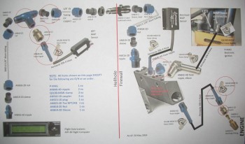
17 May 2014 — In the past week I took quite a few hours to sit down to figure out what components I needed for my Manifold Pressure & Vacuum system design. In the pic below I show my hack PowerPoint diagram that I made to keep track of all the bits n’ pieces required to build the Manifold Pressure system.

•••
24 May 2014 — Over the past week I’ve continued on in my quest to complete all my subsystem diagram pages before I leave the Middle East here within about 6 weeks! Once I return to the states, pull my Long-EZ build out of stasis, and start sniffing epoxy fumes again I won’t have the forced luxury of time (unless I take time off from actual building) to get down into the weeds of each subsystem–electrical & otherwise–that I’ve been able to do while separated from my actual project.
Within hours of posting last week’s MAP & Vacuum system diagram, I found during a relook at the installation instructions that my GRT MAP Sensor was mounted on the wrong side of the firewall: the hot side. Unlike the Electroair MAP sensor, which is fine on the hot side of the firewall (and that’s exactly where the builder is told to install it), the GRT MAP sensor must be on the cold side of the firewall. Although I had ordered the majority of the connectors, I found during my redesign that I would still use all that I ordered, so for the project manager in me it felt good to know I hadn’t wasted any (more!) money on the stuff I did order. In the pic below I show my updated hack PowerPoint diagram showing my upgraded Manifold Pressure system design:
•••
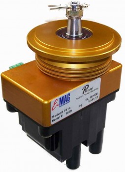
3 September 2014 — Well, after numerous initial discussions with my good OZ-based EZ-building buddy Dave Berenholtz (check out his build log here), the Sky Dynamics engine gurus, and my engine guy Tom, I decided to forego the pain that would ensue if I decided to go with a traditional Slick mag along with my Electroair electronic ignition, and then swap the initially cheaper Slick for a PMag many hours later. Yes, after Dave so graciously shared his tale of woe as to the difficulty of doing exactly what I had in mind, and after researching the electrical connections required, and the switches, and the . . . you get the idea. Much easier to just bite the bullet, design it right the first time, and then get ‘er done with one shot/one kill [See my 12 May 2014 post].
Thus, being able to fully & justly blame my mate Dave for a much lighter wallet, I called (from Qatar) up Brad at E-Mag back in late May and had a wonderfully enlightening conversation on the myriad of capabilities of the P-Mag system. Convinced that I was VERY CLOSE to making the right decision, I told Brad I would call him back to pull trigger once I was 100% sure I was going in the right direction and thoroughly research every option. In addition, I knew with Oshkosh looming on the horizon that I would want to put an order in not too far out to ensure that Brad wouldn’t be sold out when I wanted to have a P-Mag on hand.
Well, after some more intense research and another half-dozen discussions with home-builders around the world, I called Brad back a few weeks later and told him that I was completely sold on the P-Mag and would need a unit come late August/early September.
But why did I need a P-Mag then? Well, I had discussed with my engine builder Tom at Aero Engines in Winchester, VA, that after arriving back in the States I wanted to get the engine built within a month or so. Although it will be delayed just a bit, within the next month or two I should be building my new ECi IOX-340S under his watchful eye. The PMag was the last major component for the engine build that I needed, and I wanted to make sure that I had it on hand so that an experienced engine builder–knowledgeable on P-Mags–would ensure that I install it 100% correctly.
 Well, sure enough Brad gave me a call in late August and my P-Mag unit arrived just a few days later, with a bag of microwave popcorn included no less! Now that’s customer service!
•••
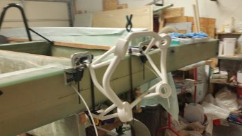
17 April 2015 — The other night I was on the computer when my Spidey sense started tingling, and I started poking around eBay for throttle handles & quadrants. For some reason I was off on a mental tangent concerning my throttle handle since, if you recall, in early 2013 in response from a discussion with my buddy Marco, I found a source for some F-16 throttle handles for us. We both like the thought of HOTAS (Hands On Throttle And Stick), and an F-16 throttle handle, besides being cool, obviously offered a way of putting switches on the throttle.
Fast forward a couple of years, with both F-16 throttle & fuselage in hand, I started realizing that the Long-EZ cockpit is just not that big. Obviously, the F-16 doesn’t have a lot of real estate either, but the Long-EZ specifically has a narrow left-side console & there’s just not a lot of room for a larger throttle handle taking up a lot space in that area. In addition, the F-16 throttle handle sticks out over the pilot’s leg, which I could see getting in the way during ingress & egress to the bird.
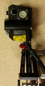
Now, back to my foray on eBay. I was actually looking for an F-100 style throttle handle, and found a couple when I searched for “throttle quadrants.” If you haven’t seen an F-100 throttle handle, it’s rather cylindrical with just 3 buttons on the top. I was actually thinking of incorporating that style into a new design, and maybe work with Marco to build a unique one out of some lightweight 2024 aluminum. But right before I logged off eBay, I searched for “throttle handle” and found a military surplus F-15 throttle handle for sale. It was $69 and seemed to be in pretty good shape (pics below). I did some quick research & felt it was a good deal, so I pulled the trigger.
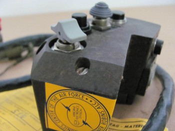
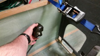
Once I received it a couple of days later, I pulled it out of the box and quickly checked the size & fit in the cockpit. The first thing that struck me was the great fit of the throttle handle in the Long-EZ’s fuselage since the throttle handle’s outboard side is completely flat vertically. This is of course because technically this is just half, or one of, the F-15’s throttle handle assembly.
Since the F-15 has two engines, this is actually the right-hand engine’s throttle handle and is located next to the left engine’s throttle handle in the F-15. If I remember correctly (I supported F-15’s years ago at Langley AFB), they are typically physically paired so they move in unison, thus their mating edges are completely flat . . . which again works perfectly in a Long-EZ!
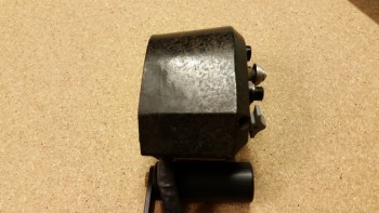
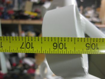
Curiosity got the best of me so I pulled out the existing throttle quadrant and laid the new F-15 throttle handle next to it. As you can see from the pic below, the new handle is only slightly wider the existing black plastic tube handle only because of the switches mounted on the side of the F-15 throttle handle.
BTW, the cost of those aviation grade switches alone was a big factor in my thoughts on this being a great deal. Unfortunately, as you can also see in the pics, I’ll have to spend some time on cleaning up the surface of the new handle too if I want to improve its curb appeal (which I will).
Now, every once in a while when I’m off on one my quests to incorporate some unique “unauthorized” modification to my Long-EZ, and am way, way off the path of approved build actions, I actually get a break. Not just a break, a BIG break that makes something really EZ to incorporate into the design. Thus, was the case with this throttle handle.
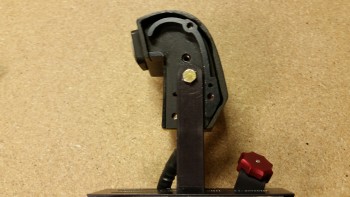
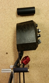
Remember, I had originally just opened the box to ensure that what I had purchased was correct and undamaged. But after checking the size & fit in the cockpit (GOOD!) and the initial size & fit on the throttle quadrant (GOOD!), I noticed the throttle handle had 3 threaded attach points on the outboard (flat) side of the handle. These 3 points all were threaded for AN3 (3/16″) bolts, which is exactly what was used to hold the black tubular handle on the the throttle quadrant that I have (AWESOME!)
I quickly took off the existing tubular throttle handle and within mere minutes had the new F-15 throttle handle MOUNTED to the throttle quadrant. Clearly I’ll have to drill a second hole to finalize the installation, but that will be all that’s required to physically mount this throttle handle. Of course I will have to contend with routing the wiring as well, but I don’t see that as terribly difficult.
One important note on fit: you’ll notice that with the attach point of the throttle quadrant lever being located close the center of the new throttle handle, the overall space used to employ this throttle handle in the cockpit is quite negligible. It literally just adds a hair more aft of the original handle, a little over an inch to the front, and the vast difference in height between old & new is minimized by mounting the new handle “low.” Thus, there’s really only a true height increase of the throttle quadrant by about 1.5″.
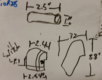
In fact, I keep a small whiteboard on the door of my shop for taking notes, listing glass cut schedules, etc. and I use it constantly throughout my build sessions. I don’t usually show my chicken scratchings on this blog, but here are the size differences I noted between the two throttle handles:
With my NEW throttle QUADRANT assembly in hand, I then checked to see how it looked & fit in the cockpit. In my opinion, it fits like a glove & is exactly what I was looking for… I couldn’t be happier!
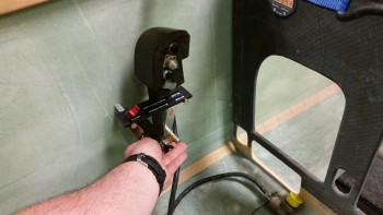
Here’s a side view of the freshly mounted throttle handle.
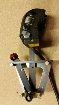
And a view from front looking aft:
I snapped a few shot to show the size comparison between the old throttle handle & the new one (note the old handle resting on the new one).
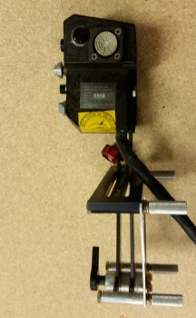
And an aft view.
 As you can see, the new F-15 throttle handle fits much better than my existing F-16 throttle handle (I guess I actually didn’t show the F-16 handle, so I’ll try to get a pic of that in a future blog post). It’s a little ironic, because as I mentioned before I actually worked on & supported F-15s while in the Air Force, and although I was trained on F-16s, I was never stationed where I was in direct support of them.
Another point in this handle blowing the F-16 handle out of the contest, is clearly this handle comes with switches mounted! That makes the task of identifying and employing switches for the landing brake, PTT, COM flip-flop, etc. much easier. Over the next week, I’ll be identifying the wiring schema for the throttle handle, and figuring out how the handle-mounted switches will be incorporated into the overall electrical system plan.
A quick clerical note, I’ll be posting this both in the Chapter 16 (Controls) & Chapter 23 (Engine) build log sections of this site (the original F-16 throttle handle posts were listed only in the engine chapter). I won’t post any more throttle handle info on this page until it pertains to the engine control linkages. In addition, check out Chapter 22 (Electrical System & Avionics) for details on the throttle handle switches, buttons & wiring.
•••
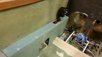
19 February 2016 — Today I started initial planning on the belly scoop for my RAM air, much along the line as what James Redmon has on his Berkut 13.
•••
21 February 2016 — I started today by continuing the design on the belly air scoop for the ram air intake. I spent a good amount of time researching the intake nozzle shape & checking my options for what bell mouth-shaped aluminum intakes are available for sale online. So far I haven’t found exactly what I’m looking for, so I’ll keep looking as I continue to dial in the shape, design & configuration of the air intake scoop.
•••
20 August 2016 — Over the past few days I also wanted to get a lot smarter on exactly how the upper & lower engine cowlings would be mounted, specifically the hardware to do so. This meant getting much smarter on Camlocs and the Skybolt Croc system. I researched a fair bit and bought a few basic Camloc components in my last Aircraft Spruce order to test them out. In addition, I’ll be using Mike Melvill’s 82° stainless steel hex-drive screws that he discussed in the Canard Pusher newsletter (CP 73).
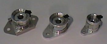
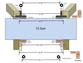
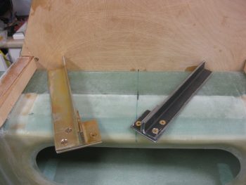
Also, I finally solved an issue that has been gnawing at me for some time: How exactly will my engine mount extrusions be mounted to the fuselage/CS spar/longerons? Well, between last night and today I finally measured all the critical players and worked out an installation solution. Since my aft upper & lower longerons are thicker (since I was originally planning on having a much wider fuselage all the way back including the firewall) AND my back seat is about 0.8″ wider, I needed to detail out exactly how thick the extrusions needed to be, and how many plies of BID to use to get the spacing correct. As you can see, on the lower mounts I’m adding 6 more plies of BID along the sides and using a 3/16″ thick 2024 angled aluminum extrusion. On the top I’ll be using 1/8″ thick 4130 steel extrusions with 4 extra plies of BID on the sides of the extrusions. The weight penalty for all this is about 1.5 lbs.
•••
27 September 2016 — Today I started off by doing a good 45 min more of research on CAMLOCs and CLOCs (Skybolt) to figure out what specific parts I need and also refine my 1/4-turn fastener requirements for the entire airplane, but specifically focused on the cowling attach.
I mentioned in my project update that while at RR, between polling builders & fliers on their prop choice, flying in front of the Silver Bullet first hand in Marco’s Long-EZ, and having a quick discussion with Gary Hertzler, I made a final decision to go with the Silver Bullet prop over the Catto 3-bladed prop. I will admit that with so many folks happy with their Silver Bullet props, that I can’t see (or justify) spending almost $2,000 more for a Catto prop when the Silver Bullet gets such rave reviews. And to be clear, this in no way diminishes my opinion of Catto props.
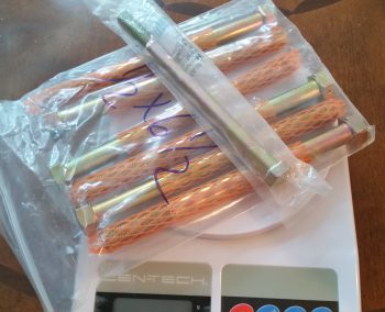
So, while out to take my truck to a service station for its annual safety inspection, I stopped at Lowe’s and picked up a Grade-8 7/16″ x 6″ bolt to use as a good estimate for comparing the weight of my current on-hand 1/2″ x 6.5″ prop bolts to the weight if I were to drop down to 7/16″ diameter prop bolts –which is what I hypothesized would be used for the Silver Bullet. After some extrapolation to account for the 1/2″ shorter bolt, and weighing all the extraneous washers, etc., I concluded that using 7/16″ prop bolts vs 1/2″ bolts would save me 0.87 lb. … at the very aft end of my airplane. That’s fairly significant considering weight & balance on these lighter birds.
Now, I did all this due to the fact that I had decided to go the 3-bladed Catto prop route a long time ago. In fact, in a discussion with Craig Catto back in early 2013, he stated that with an IOX-340S engine I should be using 1/2″ bolts to mount one of his props. Thus, when I had Sam at Saber Manufacturing make my 8″ prop extension I had him configure it for 1/2″ prop bolts.
Jumping ahead to present day, with weight data in hand, I called Gary Hertzler to discuss using 1/2″ prop bolts with the Silver Bullet. He said it could be done, but that the optimum size prop bolt would be 3/8″! Wow, even smaller than I had estimated from my layman’s research. Gary said to check with Sam since there was a good chance that Sam could merely redrill the smaller holes for 3/8″ bolts in-between the larger 1/2″ holes on the aft flange of my prop extension. Well, sure enough Gary was right and Sam is wiling & very able to do exactly that. And since I opened up the prop extension box for the first time since 2013 –with all the components new & unused– Sam will simply swap out all the 1/2″ bolts & components for the 3/8″ versions, including the crush plate. With that, this completes all the prerequisite planning & coordination and means that I will pull the trigger here soon to become an official Silver Bullet slinging Canardian!
•••
29 September 2016 — I’m still in the throes of researching, documenting and integrating the ton of info I acquired at RR. I’ve spent a fair amount of time on the phone, collectively, with Gary Hertzler regarding the prop, Sam from Saber Manufacturing regarding the prop extension, and my engine guy, Tom Schweitz, from Aero Engines in Winchester, VA regarding my engine. It was good to reconnect with Tom after over a year having talked with him last since not only did I get some refined engine specs for Gary so he could build my Silver Bullet, but things have changed A LOT in the aircraft engine world . . . e.g. ECi no longer exists since Continental bought them out!.
[One quick note on ECi: since ECi no longer exists, Continental is apparently not overly concerned about hawking it’s wares to the experimental market. Tom noted that if I have an issue in the future with ONE of my tapered-finned cylinder jugs –an ECi exclusive product– that I could quite possibly have to buy FOUR new jugs since the tapered-fins are no longer in production! He has a set of 4 new certificated ECi Nickle+Carbide cylinder jugs that he’ll swap out mine for free… well, actually the cost is about 8 pounds added back on my engine!]
I tried to find a stock photo, but couldn’t so here’s a couple shots of Silver Bullet props on my buddy Marco’s plane…
. . . and on Nate Mullins’ Long-EZ:
Ok, the good news is that I got all the info I needed for Gary and the proverbial informational cats were herded & coordinations made with all the players concerned regarding the prop. The bottom line is that I got my order form filled out and sent off to Gary! So within the next couple of months I should be the proud owner of a Hertzler Silver Bullet prop!
•••
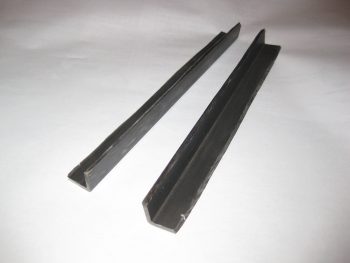
30 September 2016 — Today I finally cut the 1″ x 1″ Chromoly steel engine mount square tube extrusion into 2 “L”-shaped angled pieces. I know some may question exactly why I’m throwing in only one mount of 4130 steel. Well, I was actually going to install two 4130 steel mounts catty-corner from each other, but when the bottom mounts required the use of 3/16″ angled extrusions, I simply decided that between the weight and cost of buying more/thicker 4130 steel, I would punt and simply put only the one top side in. Yes, I considered both top engine mount extrusions being 4130, but now with my engine weighing in heavier, I’m going to employ a little Operational Risk Management here and just go with the one side to keep the weight down, and to keep from having to buy more metal! A little odd? Perhaps. But I’m going to be a little eccentric and go with this!
By the way, after I got it all cut, I matched it up to the engine mount and it was a good match!
[Note: I’ve also posted this Chapter 14 since it’s listed in the plans and relates to mounting the spar to the fuselage.]
•••
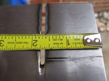
1 October 2016 — Today I cut the 1/8″ thick 2024 aluminum bottom engine mount extrusion support plate. My upper Right side extrusion originally had 1.5″ x 1.5″ legs, but since I didn’t want the top vertical leg extending so far up above the longeron, I trimmed it down to 1.25″. The horizontal leg I left at 1.5″ on the INBOARD side. I planned to trim down the OUTBOARD 1.6″ long extrusion to 1″ wide (see below). Thus, I needed the bottom support bracket to measure 1.6″ long x 2.5″ wide.
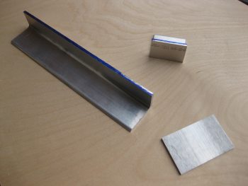
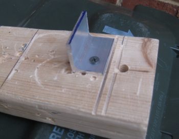
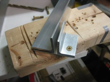
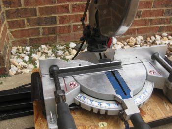
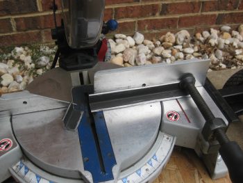
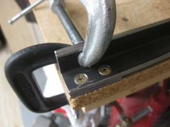
To trim the OUTBOARD 2024 upper right engine mount extrusion to 1″ wide, I needed to secure it so that the miter saw wouldn’t chew it up. I knew it needed at least one bolt hole in the bottom leg of the plate, so I marked a spot for a #10 hole. As you can see, I marked the 1″ cut line as well.
I then drilled the #10 hole and mounted the extrusion piece to a scrap piece of wood.

I then cut the extrusion down to 1″ wide on my miter saw.
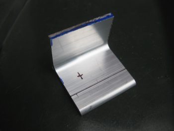
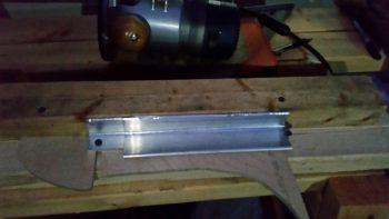
I then made up a quick jig that made it so that a 2×4 was the same height as the 1.25″ high 2024 engine mount extrusion.
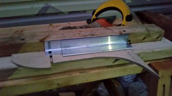
I then took my router with a 1/8″ roundover bit and radiused the edge of both short & long engine mount extrusions. Again, these are still in the rough stage and I have to finish cleaning them up.
I then cut the 0.1″ thick 4130 steel bottom engine mount extrusion support plate for the upper left engine mount. I didn’t have any 1/8″ thick 4130, and honestly didn’t order any because 4130 is some amazingly strong stuff, so 0.1″ will do the trick…. and with slightly less weight.
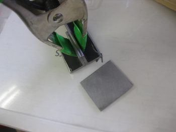
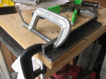
I cut the first cut using another chop saw I have with a metal cutting blade on it.
For the 90° cut I simply pulled out the Dremel tool and used it.
It only took a few minutes to cut through this steel.
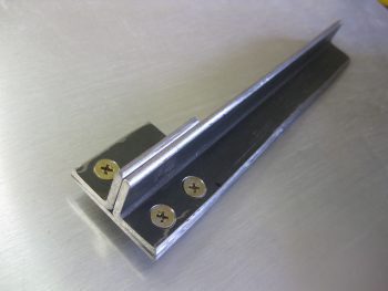
And voila! The bottom 4130 support plate for the engine mount extrusion on the upper left side.
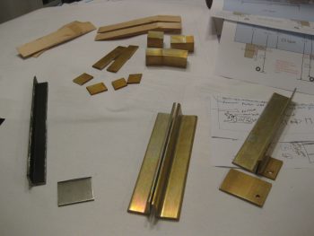
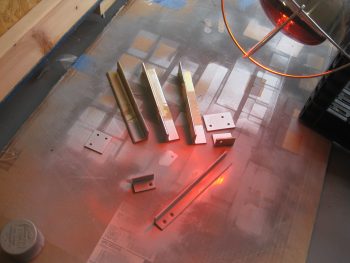
Here’s a pic of today’s take, with the WA16 wood mount wedges at the top and the engine mount extrusions at the bottom right.
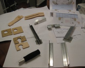 You may also note that in the pic above I included printouts of my engine mount extrusion diagrams/notes that I updated yesterday.
•••
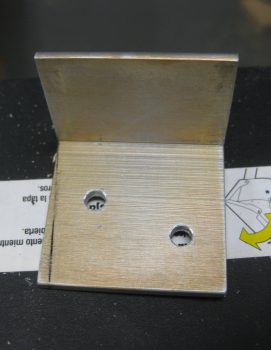
3 October 2016 — I started on the engine mount extrusions today by drilling a #12 hole down into the upper left engine mount extrusion’s bottom reinforcement plate. I then countersunk the hole in the outboard 2024 aluminum angle “L” bracket. I didn’t want to drill the other 2 holes on the other side since I wasn’t sure how much compression there would be when the engine mount was actually bolted in place (the plans say 4 AN3 screws according to a CP… but I seriously don’t know where 4 holes would fit for AN3 screws. There technically is 4 screws/bolts going through the extrusion plates into the lower reinforcement plate, IF you count the 1/4″ bolt that holds on the engine mount tube).
I did realize after I Alodined these parts (below) that I had a major brain SNAFU and should have at least drilled & countersunk the screws on the top (long) extrusion. I could then have simply drilled the holes into the lower reinforcement plate later, since it connects both sides… oh, well. No huge deal, just definitely not optimized as for as Alodine coverage.
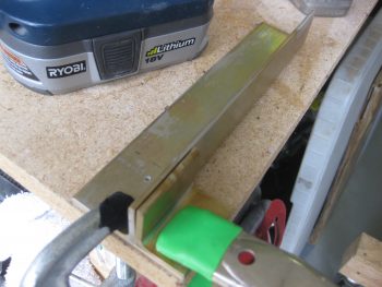
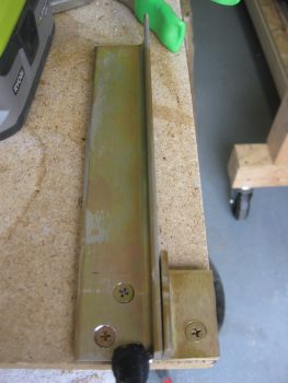
Now, my main Alodine goal for today was to at least get the Engine Mount Extrusions Alodined. I cleaned all the parts with a quick wipe down of Acetone. Then I cleaned them with a 3M pad and Simple Green, and rinsed them thoroughly. I then took them outside and Alodined them. In addition, I was also actually able to prep & Alodine the Aluminum parts for the wing bolt brackets that will allow me to mount the wing bolts in the spar quasi-permanently facing aft to greatly simplify wing mounting/removal.
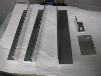
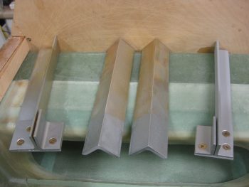
You can see below that the 3 aluminum engine mounts and the outboard spar wing bolt brackets are Alodined. Clearly I still need to finalize cleaning up the edges of the 4130 steel engine mount.
•••
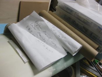
4 October 2016 — Today I spent almost 2 hours cutting all the BID required to install the top & bottom engine mount extrusions (4 total) to the CS spar & longerons. Probably not a very exciting pic… but cutting glass for nearly 2 hours isn’t exciting either! ha!
I don’t have a shot of it, but the final act of the evening was that I spent a good 30-45 minutes filing down & cleaning up the edges of the upper left 4130 engine mount extrusion. After about another 15-20 minutes more of edge cleanup, it will be ready to be cut to its final 8″ & 1.6″ lengths.
•••
5 October 2016 — Today I started off by cutting the upper left 4130 steel engine mount extrusion into 8″ & 1.6″ lengths.
I then trimmed the lower 0.1″ reinforcement plate for a final fit to the upper left engine mount extrusion pieces.
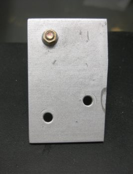
I then drilled the countersunk screw holes in the upper left extrusion mount pieces.
Here’s a shot of the 3/16″ countersunk screws mounted in the upper left extrusion mount pieces.
And all three 3/16″ countersunk screws mounted in the upper left extrusion mount pieces.
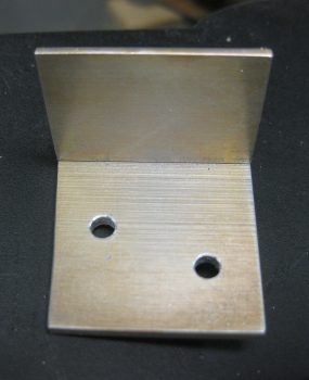
I then drilled the countersunk screw holes in the upper right extrusion mount pieces.
Here’s a shot of all three 3/16″ countersunk screws mounted in the upper right extrusion mount pieces.
Below are the 3/16″ countersunk screws & lower reinforcement plates in place on the upper extrusion mount pieces.
•••
6 October 2016 — I started off today working on the engine mount extrusions. I cleaned all my engine mount extrusions with Acetone, and then gave them a final wash in Simple Green. Once dry, I painted just the ~1.6″ tips of the 2024 aluminum extrusions with a high end silver paint that my buddy –who is an auto body guy– let me borrow a while back. I did this to protect the part of the extrusions that are firewall aft (engine compartment) and to simply make them look a little snazzier than the Alodine look.
Wth the 4130 engine mount extrusion, I primed all the individual parts and then hit the last ~1.6″ with that silver paint. Clearly I’m not concerned about the firewall forward areas on any of these, because the top ones will get painted with the cockpit interior, and the bottom ones will be buried away in the hell hole.
I have to say I had a total brain fart and used packing tape on all the aluminum extrusions when I painted them. What do you get for trying to be too snazzy? An hour of using Goo-B-Gone to get baked on tape off your extrusions!! What a waste of time, and a hard learned lesson in finding out what material in the known universe that packing tape actually sticks to!
I then took a few minutes to sand the Spruce WA16 wedges to their final shape and round over the top edges just a hair in prep for glassing these into place.
•••
14 October 2016 — After a late night building last night, today I was awoken by the FedEx guy delivering my Hertzler Silver Bullet Prop! Yeah, one more major item off the list. Getting much closer to getting this baby in the air!
•••
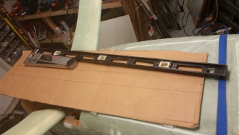
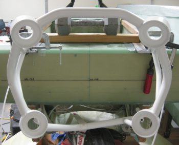
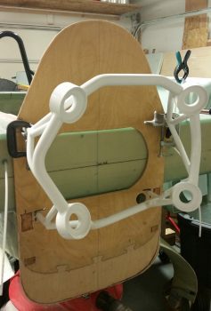
25 October 2016 — Today, in conjunction with prepping the upper engine mount extrusions for install (Chap 14), I clamped and set the engine mount into place, with it only attached to the upper engine mounts for the initial look.
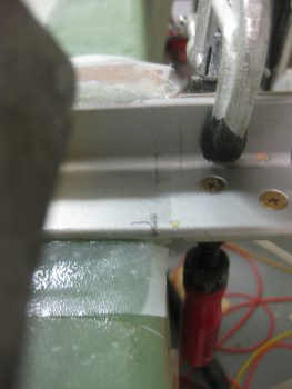
 Then came the ENIGMA: I have no idea why, since I thought I was Uber diligent in my measuring of all fuselage dimensions at the beginning of this build, but the face of my firewall is setting at about FS 125.4 vs the plan’s FS 125.0. I have to admit I was remiss in double-checking the firewall dimensions when I installed the CS spar into the fuselage, since I assumed that my spar notches were good due to the fact that I did re-check their measurements. Plus, the firewall fit flush and appeared aligned, which it is . . . just 0.4″ aft where the face of it should be.
The real affect, although over-comeable, is that the top set of engine mount brackets are setting at FS 134.5 vs FS 134.2. 0.3″ may not seem significant, but it certainly is to the W&B when you’re talking about the mounting of the 250+ pound engine, the heaviest component on this entire craft.
My initial concern was that if I simply move the mount closer (which will require some trimming of the upper engine mount stems) that it would negatively effect the clearance of the forward-mounted engine components. But since I’m using Electronic Ignitions in both magneto mounts, they won’t require the forward space that Slick mags do. Thus, if I trim a hair over 0.3″, and mount the engine with it’s normal engine mount stem to firewall spacing, I should be very close to spot on with the FS 134.2 engine mount setting.
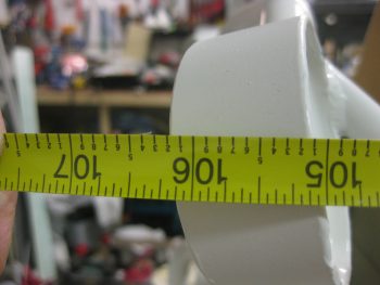
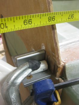
[BTW, the measurement below was taken from the face of F28… so, 28 + 106.5 = 134.5].
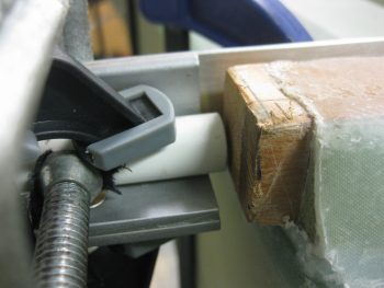
This shows the gap between the end of the right longeron and the upper right engine mount stem. Note that if the engine mount stem were left at the length in the pic below, it would actually be embedded into the firewall. The aft face of the firewall will be just forward of the double horizontal extrusion plate shown just underneath the engine mount stem.
•••
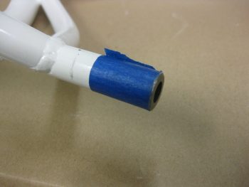
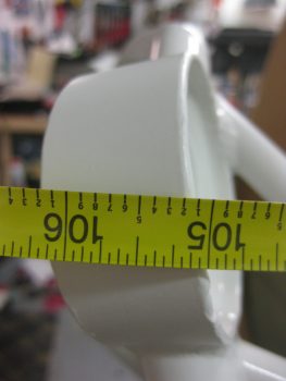
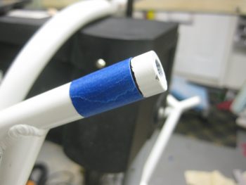
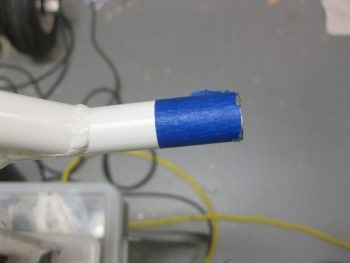
26 October 2016 — Today I started off by measuring the top engine mount posts to take 0.32″ off the end of each side.
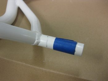
Here is one of the posts after I trimmed it 0.32″.
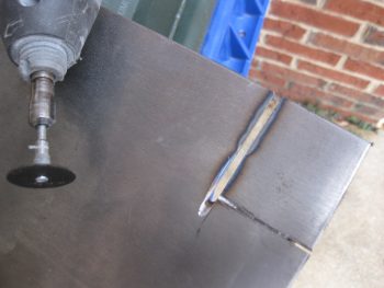
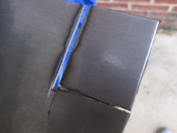
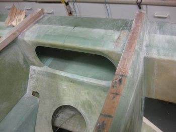
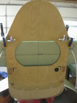
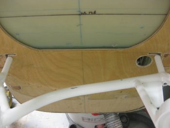
I then started marking up the firewall to cut the slots so each engine mount extrusion could transit the firewall.
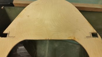
Here’s a shot with both upper and lower engine mount extrusion slots shown marked for cutting.
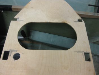
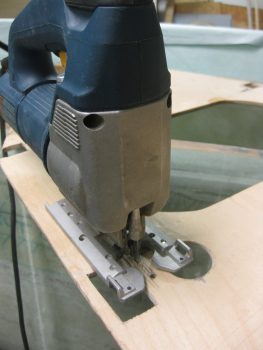
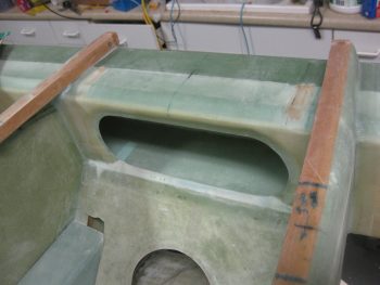
I started each extrusion slot by drilling a few 1/8″ holes for the top extrusion slots and 3/16″ holes for the bottom extrusion pass-through slots. I then transitioned to using a saber saw to finish cutting the holes.
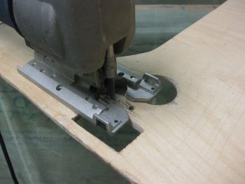
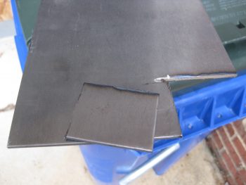
After finishing each hole with the saber saw, I then sanded down the pass throughs with 32 grit paper.
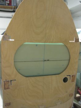
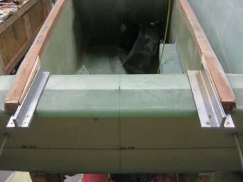
Here’s a shot of the firewall mounted with all the engine mount extrusions pass-through slots cut.
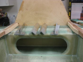
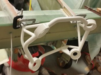
I then set the engine mount extrusions in place to see how they looked & fit.
Here’s a closer shot of the engine mount extrusions.
I then tested out my trimmed engine mount by clamping it in place on the upper engine mount extrusions.
Again, here’s a closeup shot of the upper right extrusion.
Ahh, trimming the top engine mount posts did the trick. Now I can dial in the upper engine mount rings to FS 134.2 as per plans.
I then pulled the firewall off and mocked up just the upper engine mount extrusions before I glassed them in place.
After verifying that the extrusion spacing was good, I then went to town sanding the areas that will get glass during the mounting of the engine mount extrusions.
I then vacuumed up all the sanding dust.
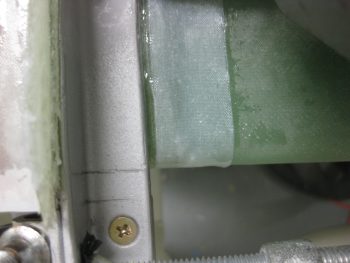
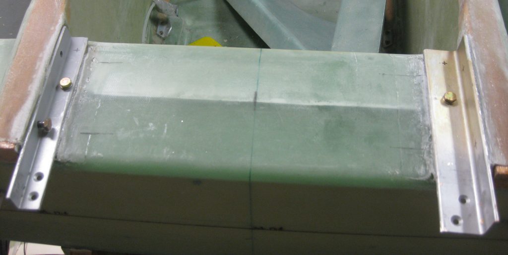
I have to say that this is quite a detailed layup. The time lapse between the pic above and below is over 4 hours. Regardless, here are a couple of shots with the upper engine mounts glassed & floxed into place.
And a shot from the aft side , , ,
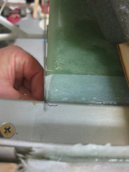
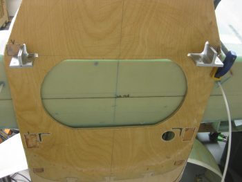
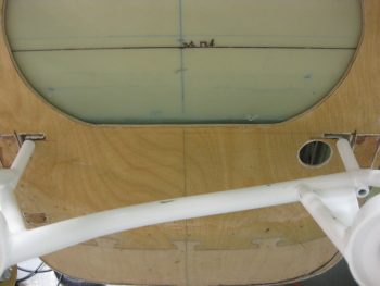
I then verified that the left side extrusion’s firewall alignment mark was good, which it wasn’t. So I spent a few minutes tweaking both side, then once I got them straight, I snapped this shot. The line at the top equates to the forward side of the firewall, while the bottom line equates to the aft side of the firewall… Thuss why I paid so much attention to getting these marks aligned properly.
Here’s the right side extrusion firewall alignment mark. Due to the angle of the camera, the extrusion and the spar, it looks a bit off.
But if you look at it from this angle, it’s spot on.
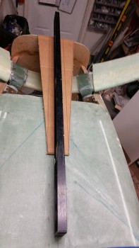
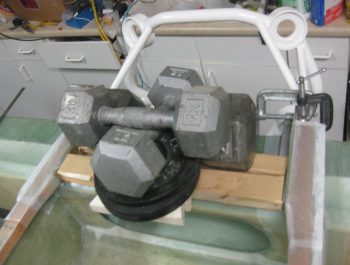
Wth my upper ending mounts aligned properly, I then wanted to better align the bottom engine mount rings. You’ll note in the pic of the plans below, the upper engine mount ring ends at FS 134.2, while the bottom engine mount ring ends at FS 134.45… 1/4″ aft of the upper engine mount ring.
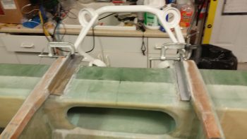
I used my level and a 1/4″ block of aluminum to check the lower engine mount rings for the proper fuselage station. They were just a bit aft on the bottom side, but a slight push forward got them to the proper fuselage station.
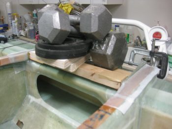
I strapped the bottom of the engine mount to the center of the landing gear to create just a slight bit of pressure, which got the lower engine mount rings to the correct fuselage station. Since the epoxy will still a bit pliable and not cured yet (I used slow hardener for this layup), this should set up the correct fuselage stations for the top & bottom of the engine mount. At a minimum, it will get the engine mount rings very close to the required FS settings so as to minimize stress when the mount gets bolted into place.
Here’s a shot of the aft end of the fuselage with the engine mount being used to ensure the upper engine mount extrusions are set in their correct positions.
•••
27 October 2016 — First off, as per plans I let this the engine mount extrusions cure until late afternoon to ensure a complete curing of the layup.
I then cleaned up all the excess glass with the Fein saw and really gave both side layups a good sanding.
One reason I went with 4130 steel on the left side extrusion is that I wanted a higher strength extrusion than stock due to a much heavier and more powerful engine. But I also wanted a low profile extrusion on the left side, since that’s where the passenger enters. I understand it’s back on the spar and out of the way, but I did want no more than an inch high extrusion on the left side.
On the right however, where the canopy is, the extrusion is 1.25″ high. The base leg is even wider at 1.5″ wide. The upper right extrusion is of course 2024 Aluminum. I pretty much left the thick pad of glass that I laid up between the right side extrusion upright and the longeron at the same 1.25″ height as the vertical extrusion leg, but I did taper it down into the longeron surface. Still, the glass under both these upper extrusions is thick, stout & strong!
I then cut the pass through holes on the firewall for the engine mount extrusions. I figured I would have to open up those pass through holes a bit, but it was really tough getting the firewall on. And although I checked the lower longerons to see if anything was messing up the re-mounting of the firewall, I couldn’t see anything.
I opened up the holes based on what I thought was some binding, but I was bamboozled by the firewall in that the real problem was at the bottom, not the top. Since the bottom longerons (or stringers) curve upward, then a bit more needs to be removed from their mounting holes to install the firewall with a straight in motion.
The next issue I encountered was the right engine mount extrusion 1.6″ bottom reinforcement & connecting plate. Since it matches the 1.5″ width of the upper right side extrusion, and due to the slight angle that the extrusion is mounted to the longeron at, I simply just could not get the screws mounted into it because it kept hitting the firewall. Obviously, this clearance issue will only get worse when the Fiberfrax and Stainless steel final cover is added to the firewall.
So I marked a slight angle on the forward side of the 1/8″ reinforcement plate (it’s still attached to the outer angle that the engine mount tube is attached to).
I then trimmed the edge using the Dremel Tool (and a face mask of course!).
I then was able to get the upper engine mount extrusion assemblies installed, and then clamped the engine mount in place.
By trimming the top engine mount posts by 0.32″ I am now able to easily attain the 134.2 fuselage station at the top aft engine mount ring. I added a pic of the engine mount post so one can get an idea of how it will look bolted in place.
I then focused on the lower engine mount posts for a bit.
The extrusion pass through holes needed to be modified just a bit, so I marked them up.
After mocking up the firewall, it was clear that the lower engine mount posts were going to need a trim as well. There’s no room for them and currently they would have to stick into the firewall for the bottom engine mount rings to be at FS 134.45. I knew I was going to have to shave another 0.3″ off of each one, so I got to work trimming each lower engine mount post.
Here’s a shot with the engine mount post trimmed to length (minus 0.3″).
I drilled a few holes for the top engine mount extrusion bolts. Here’s a shot of both sides with the one bolt each installed.
•••
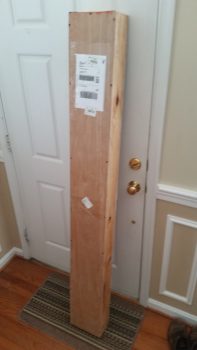
2 November 2016 —Today I started off by shipping my 8″ prop extension back to Sam at Saber Manufacturing so he can drill the holes & insert the required 3/8″ bushings (in-between the 1/2″ holes I currently have) in order for me to mount the Silver Bullet prop. Of course, originally, I had planned on going with a 3-bladed Catto prop which required 1/2″ prop bolts as per Craig Catto. In addition, Sam will swap out my 1/2″ prop bolts for 3/8″ ones and swap out the crush plate with one that has 3/8″ holes. It’s never-ending on these adjustments, eh?! One change is never without its 2nd, 3rd and 4th order affects!
•••
9 November 2016 — I started off today with a phone call from Sam Tilleman at Saber Manufacturing to discuss the modifications to my prop extension. Since I found out from my engine builder, Tom Schweitz, that my engine mount bolts are 7/16″ vs the original 1/2″ bolts that they were identified as, I worked out the plan with Sam for him to drill those out as well. Although a bit more money to have Sam modify the prop extension, again this actually worked out serendipitously in that having 3/8″ bolt holes drilled in between the 1/2″ bolt holes on the prop side of the extension, and 7/16″ bolt holes drilled in between the 1/2″ holes on the engine flange side, simply gives me a prop extension with 1/2″ lightening holes machined on each end. Talking to Sam, this is pretty much the same configuration that Klaus Savier has on his airplane…. definitely not a bad model to emulate!
•••
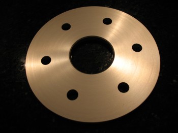
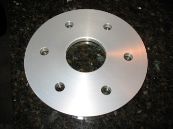
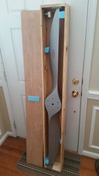
13 November 2016 — Today I got my prop extension back from Sam at Saber Manufacturing. As you can see, he added in 3/8″ bolt holes and bushings for the Silver Bullet prop on the prop side, and he also added 7/16″ bolt holes in between the 1/2″ holes for mounting the extension to the engine prop flange.
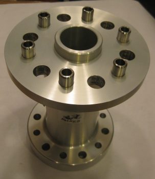
For comparison, here’s a similar shot of the prop extension back when I bought it in 2013:
•••
28 February 2017 — I finally did a bit of research and decided on the style of latch I wanted for my oil dipstick access door on my cowling. I like the way the one below operates so I picked one up from a guy off of Ebay. For those curious it’s a Hartwell H2868-1. I like this specific version since most of the ones that are this style simply have a large square plate with a hole in each corner for mounting. With the wings of this “H” style it will allow me to bend those just a hair to match any curvature I may have on the oil dipstick access door, which in turn, matches the curvature of the upper engine cowling. In addition, the main reason I wanted a latch-for-the-hatch is to preclude the complexity and pain of having to use a screwdriver to undo any number of CamLocs just to check the oil! Plus, as with everything we do, I simply think it looks cool… ha!

•••
15 March 2017 — After another quick consult with Nick Ugolini, and after finally getting to the end of the proverbial research road on my Camloc/Skybolt solution (based on Nick’s fastener test) I had a Skybolt order sitting on my computer screen ready to go. I wasn’t planning on buying these parts this month but since I had just spent over an hour performing some online price comparisons, and these were the lowest price I could find, I decided to not keep this in the queue any longer and pulled the trigger.
So, as with most everything on this build, besides the inevitable nickel & dime onesy-twosey pieces that will crop up and need bought, this purchase does it for my Camloc/Skybolt 1/4-turn fastener system. This will allow me to virtually (but not completely) go Camloc on my cowlings, RAM air/hell hole cover, internal cockpit hatch covers, etc.
Concurrent to my Skybolt research and order trigger pulling, as I was watching Mike Beasley’s progress on his baggage pod installation, with the help of the ubiquitous baggage pod install master, Steve Beert, my curiosity around some particulars of the baggage pod installation got the best of me. So late last night I pulled out my notes and ended up back on James Redmon’s Berkut13 site to see what he had to say about it.
I knew that if I wanted to use Camlocs on my baggage pods that I needed to use the removable grommet 4002-NS vs the SK-O18S grommet that is held in place with a snap ring. If these numbers are new to you, welcome to the club! As with so many components on these airplanes there are literally hundreds, if not thousands, of possible combinations. Thus, I’m very thankful that Nick Ugolini documented his Camloc test.
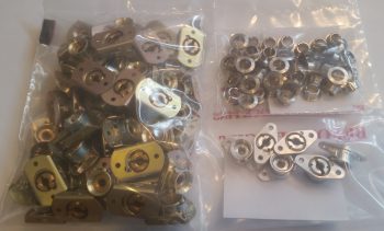
Moreover, you may note that the the face of these grommets below look a bit different (to be clear: the grommet is the flange looking deal while the stud is the “screw”). The one on the left is the non-removable (without tools) Skybolt SK-O18S, which I’ll be using for the majority of my Camloc installations. The Camloc 4002-NS grommet on the right is meant to come out when the Camloc is unfastened and is used in places like the aft edges of the cowlings and on the baggage pods.
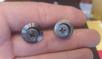
This view below clearly shows the difference between the SK-O18S on the left (secured to the cowling with a snap ring) and the removable 4002-NS on the left (for aft top/bottom cowling securing and baggage pods).

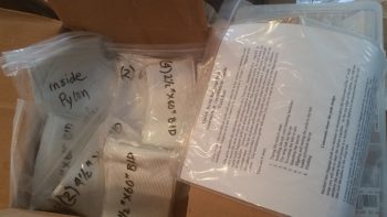
In addition, I discovered a nice surprise while re-reading stuff about installing the baggage pods on James Redmon’s Berkut13 site: he mentioned that Gary Hunter provided all the BID tapes required to mount these pods to your Long-EZ! What?! So I went digging in the box that I’ve had for a few years now and sure enough at the bottom was a box with the instructions in there and a bunch of MARKED bags with the BID required to mount the baggage pods . . . Now, how cool is that!!! Who knew?! ha!
One final point. As I was reading through the how-to manuals & notes on installing the baggage pods, I discovered –the day after I got my Skybolt order!– that I needed one more of the -7 studs that I of course don’t have on hand. See?! I told you! Build an airplane if you love never-ending goose chases… ha!
•••
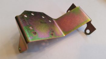
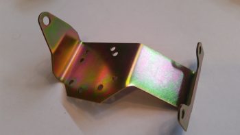
27 March 2017 — Today I received my fuel injection spider mounting tab that goes on the top centerline of the engine. Yet just another item that will go on the shelf for the time being.
•••
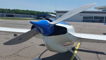
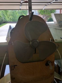
29 April 2017 — Today I thought I’d show you my new environmentally friendly electric engine install with its high efficiency 3-bladed prop (no, NOT a Catto!).
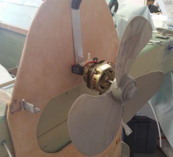
You can see this will save me a ton of weight and I’ll probably be the first Long-EZ that has NO aft CG problem! HA!
•••
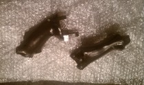
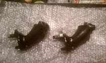
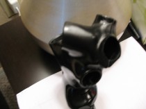
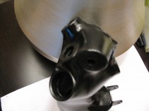
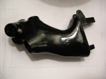
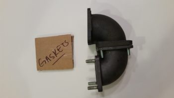
12 October 2017 — Today during my shop shenanigans I heard a delivery truck stop by. A little while later I did in fact find a couple packages on my doorstep. The first one was from Airflow Performance and had the 90° and 85° air intake elbows that I ordered, with the associated gaskets.
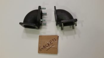
These elbows make up the physical mount and air intake for the air coming out the of Silver Hawk fuel injection servo into the Superior cold air plenum. In the pic below, the nose of the aircraft would be to the left, prop to the right. Since all the cold air induction plenums are built for forward facing engines, to incorporate one I had to get my air turned around.
To be clear, this isn’t something I did willy-nilly, although I know a number of Cozy builder/ drivers have done it with reportedly good success. I conferred with Kevin Murray at Sky Dynamics, my IOX-340S engine builder, Tom Schweitz, and just within the last week I had a good discussion regarding getting this air turned around with Pete at Precision Airmotive, the maker of the Silver Hawk fuel injection system.
I’ve also been discussing this quite a bit with Chris Seats, a fellow Long-EZ builder. While Chris is not using the Silver Hawk FI (he’s using the EFII system) he is using the Superior cold air induction plenum, so he has to turn the air around as well. Chris is constructing his own air intake duct out of Carbon Fiber, but was curious about the weight of these combined elbows… which is 1.7 lbs. total.
•••
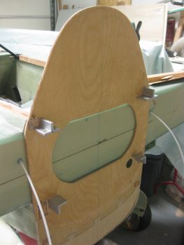
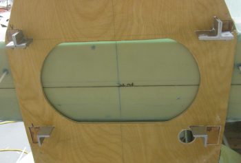
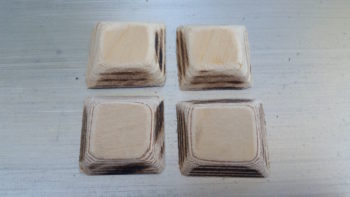
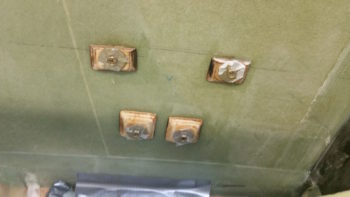
30 October 2017 — The weather was unexpectedly sunny & nice, so I took the opportunity to cut 4 beveled plywood hard points to reinforce the aluminum threaded inserts that the throttle quadrant will mount to. I then rounded the corners with my sanding block.
A bit later I drilled the appropriate size holes and then trimmed the top 2 plywood hard points… this throttle quadrant is marketed more towards RV bubbas so it mounts a bit odd going into a Long-EZ with the top mounting bolts almost even (but maybe 0.050″ low) with the top of the throttle quadrant plate. Not a huge issue, I just either had to trim down my top hard points or have to deal with them sticking above the top of the armrest.

To be clear, I had sat in the pilot’s for quite a while in an attempt to ascertain the right spot (for me) to mount the throttle quadrant. Since I’ll have to redo the actual lever for the throttle handle I have some flexibility on the height and left/right position of the handle, thus the main issue to determine today was forward/aft positioning and did I want it sunken a bit below the surface of the armrest or not [I chose not].
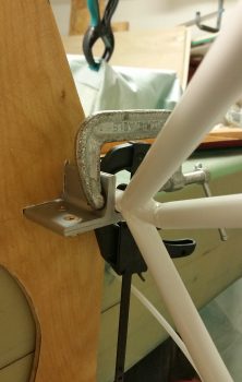
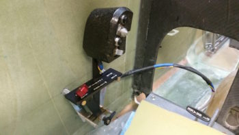
This pic below jumps ahead a bit after I had decided where I wanted the throttle quadrant mounted and subsequently after the holes in the left fuselage sidewall were drilled. I set the throttle quadrant threaded aluminum mounting posts into the holes, climbed in and ensured that this is where I wanted it before I finalized the install. I did move it forward 0.4″ from my originally planned mounting position. As you’ll note by the pics below, obviously I liked this spot so I pulled the pressed forward with the install.
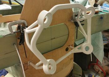
I prepped each threaded aluminum insert by taping up the outboard (open) ends of each one, and then bolting a tape-covered washer to the inboard open hole. I then mixed up some flox and started by floxing the threaded aluminum inserts into each plywood hardpoint. I then floxed the threaded insert/plywood hardpoint assemblies into their respective holes. Of course the back (outboard) side of each plywood hardpoint was slathered with flox as well, providing a fair amount of surface contact area for added strength.
[In hindsight, if I had really taken note on how close the bottom 2 hardpoints were together, I might have just made one longer plywood hardpoint. No worries though since what I used below worked fine too.]
While the floxed-in threaded insert/plywood hardpoint throttle quadrant mounting assemblies cured, I then prepped the layups by cutting and prepregging 2-plies of BID for each hardpoint.

After the flox cured the majority of the way, I then mixed up some more epoxy, wet out the prepregged 2-ply BID layups and went to work. Here you can see all the threaded insert/plywood hard points glassed and peel plied. I then set a heat lamp on them (….my shop was a balmy 66° F).
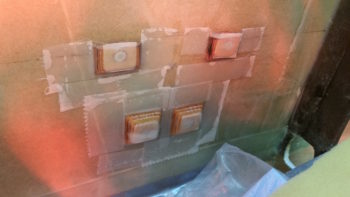
It was getting late so I left the threaded insert & plywood hardpoint throttle quadrant mounting assemblies alone to cure in peace while I went upstairs to get a bit of research in.
•••
31 October 2017 — Today I started out by removing the peel ply from the cured throttle quadrant mounting hardpoint layups and then cleaned it all up. I then drilled the holes into each of the 4 hard points, removed the protective plastic wrap I had stuffed into each one to keep the nasty stuff out, and then cleaned up each hole to allow me to test mount the throttle quadrant.
I have to say it all looks good and I’m very pleased with the position of the throttle quadrant.

•••
3 November 2017 — Today I spent quite a while determining the exact mounting location –specifically distance from the fuselage sidewall– of my throttle quadrant. With this throttle handle, I have to be careful in how I route the throttle handle cable to prevent chaffing or rubbing. I’ll be constructing a new, specifically designed throttle handle lever that will route the cable through the lever to ensure strain is minimized and keeps the cable from rubbing on the corner of the throttle quadrant plate.
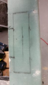
After marking off the area for the throttle quadrant on the top of the left armrest, I then cut the area out using my trusty jig saw.
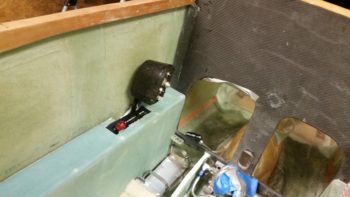
Below you can see the throttle quadrant mounted on the sidewall with the left armrest in place. You may note also that I made a bit of a blunder in my up/down placement of the throttle handle IF I wanted the top of the throttle quadrant plate even with the top surface of the left armrest, which I did.
Ions ago I had drawn a line across the fuselage sidewall where the armrest would be located. Unfortunately, this line was for the TOP of the armrest sidewall, but NOT the top of the armrest. Essentially, I had drawn the intersection line of the armrest sidewall and the armrest top. I kept this in mind when I mounted the throttle quadrant mounting hardpoints so the throttle quadrant base top was supposed to match the armrest top, but somewhere in the process I induced a slight mismatch. Currently the throttle quadrant base sits about halfway down in the top of the armrest. No big/uncorrectable deal, just another issue to work through.
This shot shows a bit more of the armrest fitted into the fuselage.
•••
20 February 2018 — Today I spoke with Bill at Airflow Systems to see about the possibility of swapping out my 2008X 17-row oil cooler for a 2006X 13-row oil cooler. Since I’m not using tapered cylinders on my IOX-340S engine now and my compression is not super high (9.3:1) then I’m assessing making my life easier (we discussed the specs and oil cooling requirements of course) when it comes to oil cooler placement and installation by picking up an oil cooler that’s about 1.5″ less in length than I have currently.
•••
22 February 2018 — Today I set out to finalize my oil cooler decision…. round 2. Unfortunately, I didn’t get it right the first time. You see in my early thought processes I figured the Long-EZ was a well-developed design and folks had pretty much figured it out and it was all plug and play. Boy, was off there! Ask 12 Long-EZ builders how to do one thing and you’ll get 15 ways to do it…. with each one the exact right way to do it!
When it came time to acquire an oil cooler I just went with Mike Melvill’s choice –a 17-row cooler– because it was in fact his cowling that I was using. Makes sense, right?! WRONG! I ordered my Airflow Systems 17-row 2008X oil cooler based on this info, but then when my knowledge matured on how the internal configuration was inside the cowling, I realized the 17-row 2008X was way too big. In fact, I figure Mike M. must have turned it “sideways” (in comparison to it’s normal installation) to fit that monstrosity in there [I say “monstrosity” when in fact it’s only 1.6″ taller/longer than the 13-row 2006X… but of course we’re talking a Long-EZ here, and again, everything is TIGHT].
I had kept ahold of the 17-row 2008X because I had planned to run ECi’s tapered fin cylinders which, while cutting a few pounds off the engine, also, by their very design, had less cooling surface area. However, after some discussion with my engine builder I decided to go a more traditional route (for increased maintainability, cooling and building ease while reducing cost for future overhauls/emergency replacement if stuck in Podunk nowhere) and install standard cylinders with the higher compression pistons…. again, 9.3:1 compression.
With my new cylinders on the engine I decided once and for all to finalize my oil cooler selection… again, although I had the 17-row 2008X. I engaged Bill Genevro, Managing Director of Airflow Systems to go over my engine oil cooling requirements again (BTW, I’ve had fellow Canardians inquire why I went this route vs. the ever venerable Stewart-Warner cooler. Well, Air Systems was recommended to me by a couple different sources associated with the Red Bull racing team. That, and honestly… for half the price out the door, I just wasn’t yet prepared to bow down to the altar of Stewart-Warner).
I asked Bill the following:
A) If the 13-row would work in my configuration? (a bunch of spec emails ensued), then after the specs supported it (Bill said it would work fine, but he would have preferred that I still use a 15-row…. but I see so many O-320s using 9-rows, that I don’t think I’m off the mark. In fact, just for some perspective, the 2006X oil cooler is listed for -360 and -540 motors, so it’s not a wilting flower in its own right.)
B) If I could swap out the bigger oil cooler for one two sizes smaller? … he said I could.
Before I fired off the 2008X out to Airflow Systems in California for a swap for the 2006X, I made up some paper cutouts of these 3 biggest oil coolers (17, 15, 13 rows) to test them out on my lower cowling, which has a nifty spot prepped and molded in it that just needs to be cut out for the oil cooler.
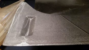
The smallest 13-row oil cooler, was –not surprisingly– a near-perfect fit.

Here’s another shot so that you can better tell where I’m situated on the lower engine cowling: the forward left corner.

The 17-row 2007X wasn’t too bad, but it was starting to overhang out over what will be the air scoop for my Berkut-style armpit intakes.
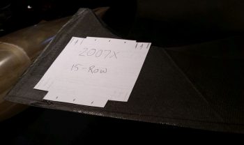
I didn’t do a full separate paper cutout of the 17-row 2008X, just the center part which has the biggest footprint. As you can see it goes right up to the left edge of the lower cowling. This could present an issue in that I don’t know yet where the exact left edge of the cowling is located since it may very well need to be trimmed to fit properly.
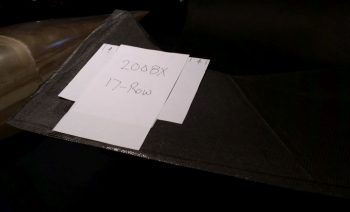
If you’re wondering, what is that indentation on the engine cowling? So did I for a couple years (remember, I bought my cowlings at the VERY beginning of my build). Mike Melvill was quite clever in adding this to his cowling plug in that it’s the air scoop that hangs down in the airstream at the front of the oil cooler opening in the cowling (see two pics below). As Dick Rutan found out in his tests for oil cooling on the Voyager, configuring the oil cooler opening in this fashion more than doubles the Delta ‘P’ from 1.8 H2O with just an opening to 3.8 H2O with this scoop preceding the oil cooler opening.
Now, I just had a lengthy and informative conversation with Joe Coraggio the other day, and something Joe said in regards to weight reduction really resonated with me. Joe relayed that he had in fact made his cowlings from scratch out of Carbon Fiber, but that in the ensuing mods and redos on the cowling construction, which then mandated a bit more filler here and there, that his cowlings actually turned out to be pretty much the same weight as stock E-glass cowlings. Not bad, and definitely better than if he had started with just E-glass, but it gave me a huge lesson learned: Don’t modify the cowlings unless absolutely necessary! I mention this because Mike Melvill was able to cut the weight of the original E-glass cowlings down by over half on his carbon fiber cowlings, which I now have a set of… the one last thing I want/need to do is start mucking around with them and end up in Joe’s situation (I thank Joe for being honest and frank about his build adventures, and sharing with me and others to allow us to optimize our own builds…. thanks Joe!)
With all that in mind, I measured the width of the pre-molded oil cooler scoop on my lower cowling: 5.5 inches.
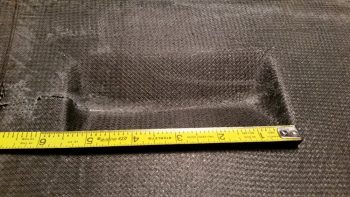
In addition to my discussion with Joe, I of course went back and reviewed my notes on oil cooling before spending any time, energy and money sending my 2008X oil cooler to be swapped out with a 2006X. The last thing I wanted to do was burn more time and money on something that I may have overlooked, or worse yet, discovered years ago and simply forgot in the present day only to revert back to a previous less-than-optimized decision (happens way too many times in an extended build like this… maddening!).
I reread that so many builders state that the place to put the oil cooler is simply just below the alternator and starter so that the air exits with the exiting engine cooling air. Probably not a bad place at all to put it, and it appears to have worked for many. However, the criticism of the “plans” position prior to these builders/owners swapping their oil cooler position is often unfounded or misplaced (IMO) since I’ve noted how in so many of these cases they simple disregarded the findings that Dick Rutan discovered in prepping his oil cooling system for an around-the-world flight in the Voyager aircraft. Yes, it may be a bit counterintuitive, and I’m sure there is some credence to the ever-present drag argument on this design, but personally I’m not going to argue with Mike Melvill or Dick Rutan, who both have flown this oil cooler design around the world . . . 3 times!! If you think I’m nearly name-dropping, check this out:
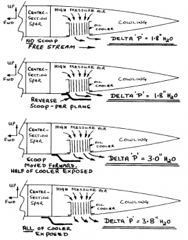
Here’s a real-world example of this oil cooler configuration on Mike Melvill’s Long-EZ. You can see here that Mike did in fact turn his oil cooler so that the oil lines enter in through the top of the oil cooler facing forward vs the top of the oil cooler facing inboard towards the engine (right), the latter being how I’ve seen this configuration on the majority of canards. My configuration –again, the latter– allows for significantly shorter oil lines. In addition, there’s no cooler body overhang above the air intake scoop. Of course final install will be mandated by the final configuration of the engine situated within the cowling, so at this point I’m still technically in the planning (e.g. prognostication) stage.
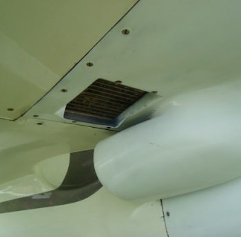
Ok, so with my overarching goal of get this bird in the air combined with my self-ascribed mandates to “do no damage” in not messing about with cowling redesigns… and don’t change a design that works (i.e. this oil cooler position/configuration), my final check was to assess the actual cooling area of each oil cooler in regards to the pre-molded oil cooler scoop.
By this point the 17-row 2008X was a clear No-Go. I then checked the 13-row 2006X and the actual airflow area width was spot-on with my pre-molded oil cooler scoop width of 5.5″.

As you can see, the 15-row 2007X’s (which honestly I was leaning towards “making it fit”) actual airflow area width was just too wide compared to my 5.5″ pre-molded oil cooler scoop width and would require a COWLING MODIFICATION which as I’ve stated above is in the just-say-no category.
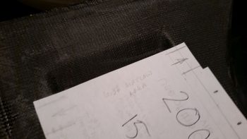
So, the 2006X was the clear winner, and with that I relabeled the box and sent the 2008X back to Airflow Systems this afternoon.
•••
20 June 2018 — Today I finally get around to cracking open the box that contained my exhaust pipes after all these years. Yes, I should have been more diligent and checked them much earlier, but I’m happy to report that upon initial inspection they looked good.
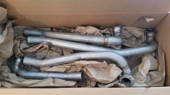
•••
5 July 2018 — Today I received yet another L12 micro-linear actuator that I’ll be using to manipulate louvers that will cover the oil cooler to adjust the airflow for optimized oil cooling temps: louvers closer to closed in the winter for less engine oil cooling and pretty much wide open during the hot summers, with stages in-between during the fall and spring.
The switch that I also bought from the Robot Shop is a latching type switch (analogous in function to a latching relay) that will allow a simple actuator to be stopped at discreet positions –versus just merely fully opened or fully closed– to allow for a myriad of settings to dial in the oil cooler to temp during flight ops versus having to mess around with making, sizing and attaching oil cover plates on the ground.
As a point of note, I got the louver idea from Marc Zeitlin who incorporated this simple mod on his Cozy IV with great results. The main difference in my configuration vs Marc’s is that Marc incorporated a cable to manipulate the louvers whereas I will be using a significantly lighter micro-linear actuator.
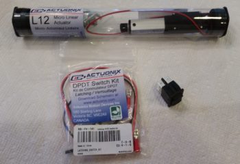
•••
9 August 2018 — While I was looking at some pics I found a shot of the cowlings from around 2012 that had a document included that I hadn’t seen in quite a while. While looking for the document I finally completely unwrapped the Berkut-style armpit intakes for the lower cowling. As you can see, I decided to grab a couple of shots of these . . .
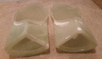
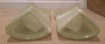
•••
26 October 2018 — Today I finally got the remaining significant aircraft assemblies for my Long-EZ build hauled down to North Carolina. The big 3 components that I moved were the engine, the canard and the panel mockup.
Although not overly difficult, the engine did take a good bit of machination to ensure all would be secure and safe during transport.
My first concern was that since I have the engine pert near full of pickling oil, I couldn’t just simply remove the oil quick drain valve on the bottom of the cold air induction oil sump since it was keeping all the oil where it’s supposed to be! And since the oil valve protrudes downward a good 3-4″ below the oil sump, it clearly need some nearby supports to keep it protected.
Thus, it was quickly apparent that unlike the thick styrofoam that I had used in hauling the engine home from the shop, I needed a transporting base to keep the bottom of the engine (e.g. the quick oil drain valve) off of the truck bed while in transport.
Being a rather clever fellow (ha!), I grabbed a spare 2×6 I had laying around and concocted this thing here. The 2×6 upright “post” towards the front of this thing is situated along the bottom of the engine case in between and just forward of the alternator and starter, where the case has a little flat spot. The quick oil drain valve is situated inside the open area made up by the boards running on each side of the vertical post.
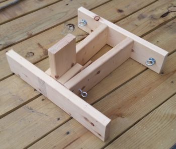
As you can see somewhat, I then strapped my engine transport base to the bottom of the engine using 2 tie-down straps. I also prepped the engine for a good road trip by encasing what I could in large garbage bags and then wrapping it all with plastic wrap.
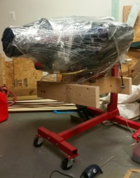
Here’s a more closeup view…
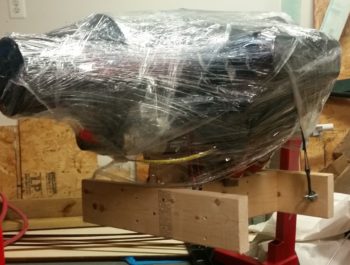
After the 20+ minutes of setting up and configuring the engine hoist, then came the somewhat laborious process of undoing the engine-to-engine stand bolts, then hoisting the free engine –with the attached transport base– into my truck.
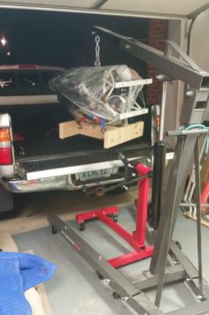
I then secured the engine into the bed of my truck.
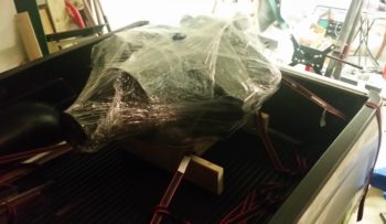
About 15 hours later –after unloading the rest of my stuff into the storage unit– I then got my engine unloaded into my friend’s garage down in NC. It’s hard to tell in the pic, but there was a steady light rain coming down at this point.
In addition to my engine, I had also hauled down the much required engine hoist and engine stand on the trailer.
I then simply reversed the process to get the engine back off my truck and onto the engine stand.
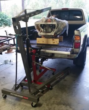
And Voila! Then engine is now safe and sound in NC!
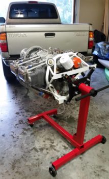
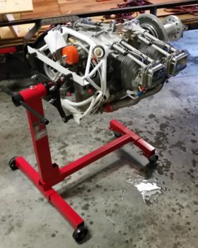
•••
4 October 2019 — As I mentioned in my post on Rough River, that while be-bopping around the flightline with Marco looking at all the various canards it hit me that the airplanes without spinners on the back end just looked unfinished. He agreed (he agrees with just about EVERYTHING I say… haha!)
Flyable? Certainly. Lacking something? Yep, that too.
Especially when looking at the aft end of a row of Long-EZ’s with Hershey Kiss style spinners, then seeing a bird without one. Naaahh, not the look for me.
I had thought about flying without a spinner for a while until I made up my mind on this issue, but my mind has definitely been impressed upon now that I want a spinner to finish out the look I want.
But then came the questions of what/where/who/how? … followed by how much? And when?
The style I prefer is the same as the spinner Marco has on N977JT. It looks almost exactly the same as the NTX pressure recovery spinner that James Redmon made a batch of, shown here:
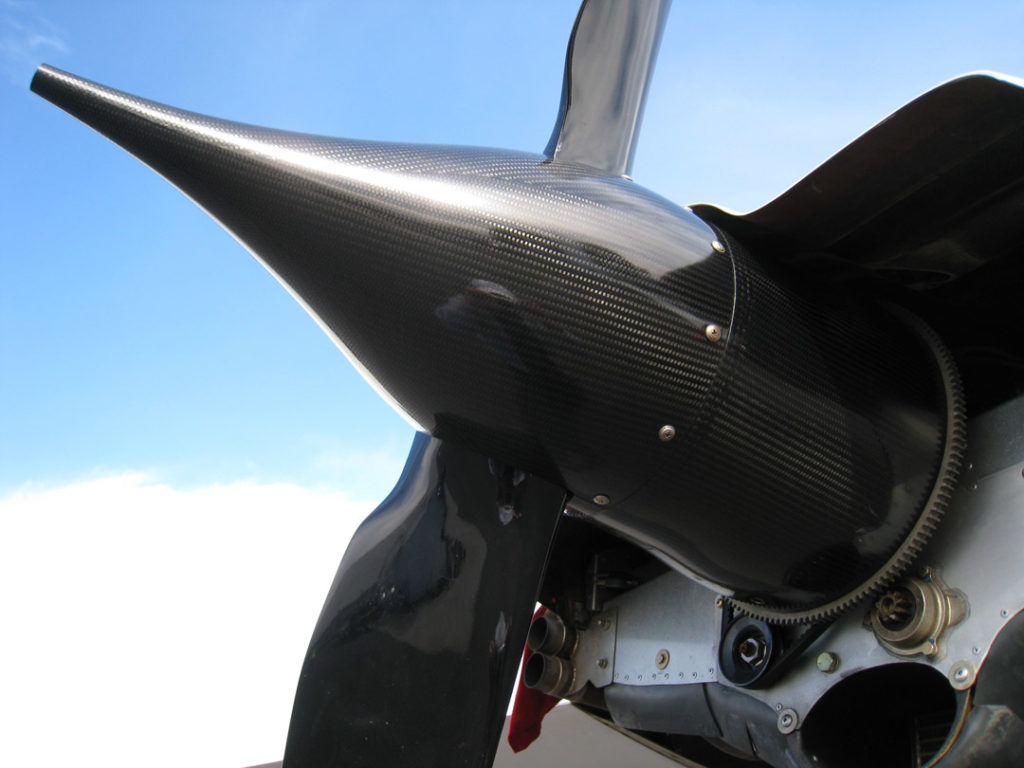
Interestingly, I asked Terry Lamp –builder of Marco’s Long-EZ– if he made the spinner himself? Or did he buy it from James Redmon? …. Along with a comment I made of not knowing James made these spinners circa 15 years ago.
To my surprise, Terry stated that he bought the spinner for Marco’s plane from Ken Miller. Ahhh, I thought… that made sense since in the last couple of months Ken Miller had asked on FaceBook who all was interested in him making prop spinners again. I may be slow, but I can connect dots.
I planned on contacting Ken Miller as an option for my spinner upon my return from RR.
Another option I had in mind, Klaus at Lightspeed Engineering, was apparently no longer a real option since Mike Toomey reportedly grabbed the last aluminum spinner bulkhead, one of the last few spinners, and then had to fabricate his own flow guide by using the spinner as a mold [BTW, I’m not a big fan of the rounded flow guide that terminates near the prop extension shaft vs. the flow guides that contact and cover the flywheel as the NTX flow guide does above].
One option that could possibly have been a lot cheaper was to ask Mike Toomey to make me one. But then that would have still required the machining of an aluminum bulkhead (given he even had time to do it)… too much work with my project already so far behind due to this protracted 2-year move!
Upon my return from Rough River, I contacted Ken Miller via FaceBook and also reached out to Noe Ramirez down in Mexico (who used to work for either Klaus, or Dave Ronneberg… sorry, don’t remember which one) to inquiry about the possibility of getting a spinner made.
Well, Ken said he decided not to make them since Craig Catto had started making them… (something that Mike Toomey had mentioned at RR as well).
Strike 1.
Then Noe replied and said he could, but the price, especially for shipping, would be exorbitantly high.
Strike 2.
Then yesterday afternoon I had a good discussion with Craig Catto’s daughter Nicole regarding hershey kiss style prop spinners. Since I have a Hertzler Silver Bullet prop, Nicole said they could send me one unclear-coated since I would need to cut out the prop blade notches on the spinner myself, then clear coat it or paint it.
I asked for pics and she sent me these 2 pics below… stunning and exactly what I was looking for!
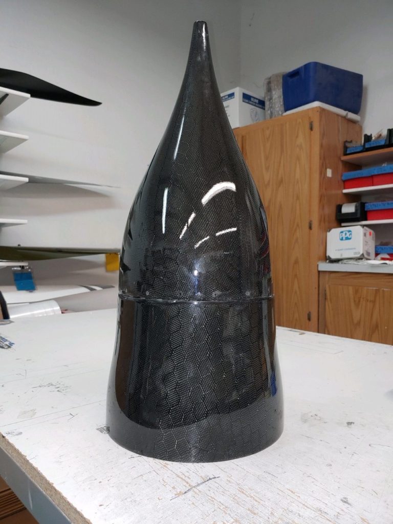
If you’re on the Long-EZ and Vari-Eze FaceBook page you may have noted that Craig Catto made a post on his prop spinners about 2 hours after my phone call. They had one on hand and had closed before I could ask my last couple of questions.
I had errands to run the next morning and by the time I called Nicole, some barbaric neanderthal that goes by the name Dave Anderson had swooped in and STOLE my prop spinner (haha!!). Nah, all is good since Dave has a flying Long-EZ and needed one now. But I did place my order with Nicole for one of these stunning prop spinners.
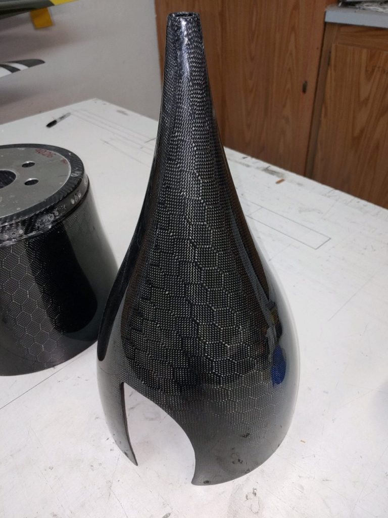
3rd times a charm!
I’m glad I ordered it now since I do NOT want to cover up the fantastic carbon fiber pattern with paint. I will now incorporate this black spinner into my paint scheme to allow for this carbon fiber beauty to be shown in all of its natural splendor.
•••
27 December 2019 — Today I finally got around to hauling my engine over from my local friends’ garage to mine.
It’s always quite the lengthy ordeal to attach the transport base to the bottom of the engine, remove the engine stand (red) and then secure the engine in the truck. While transporting the engine to my garage, I hauled both the engine hoist and engine stand as well on my trailer (since there’s no room for them in the bed of my truck).
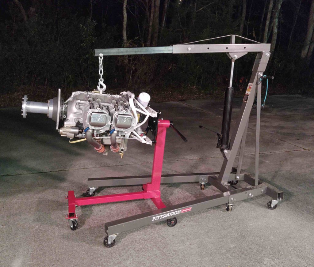
After I got to my house the process was reversed: engine came out of the truck on the hoist, then the wood transport base was removed, and finally the engine was once again attached to the roll-around engine stand.
This seriously makes it so that all my aircraft components are back in one location: my house.
•••
8 February 2020 — Today I finally received my Hershey Kiss spinner and flow guide from Catto. It took them a while to get it to me, but it looks high quality and definitely the style I wanted. Moreover, the carbon fiber weave pattern is just really cool!
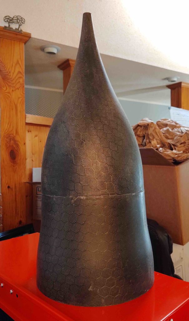
•••