
I started out today researching and reacquainting myself with the wheel pant install tasks that I had undertaken about 2 years ago. I then wrote out my wheel pants install task list.
When I went down to the shop to do some major rearranging before jumping into the start of the Wheel Pants 3-DAY BLITZ, I realized that there was quite a bit I had not yet finished on the firewall.
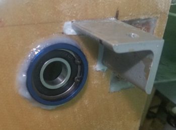
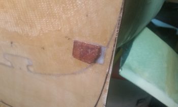
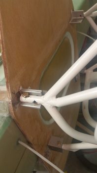
First off, I pulled the protective tape off the components of the CS123 control bearing floxed in place on the firewall.
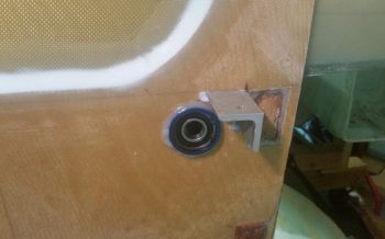
Here’s a closeup of CS123 floxed into the firewall. I realize (yes, after looking at my notes!) that there was a reason I was waiting to do this, and that the plans have you install the actual firewall Fiberfrax and metal sheet in Chapter 15. Well, I was in Chapter 16 . . . oh, well. There’s definitely a 6 and 1/2-dozen thing going on here because I really wasn’t ever keen on floxing this thing to a metal covered firewall. So I’ll deal with the minor inconvenience of mounting the Fiberfrax and firewall sheeting over top and around my floxed-in CS123 bearing.
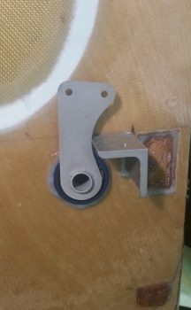
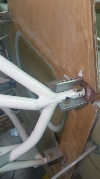
Here’s another shot with the aileron control tab slid into place. A couple things on the elevator control tab . . . if it looks closer than it should to the lower right engine extrusion, it is. First off, that’s because the engine extrusion is 1.25″ wide vs. the plans’ 1″ wide. Thus we’re clearly missing 1/4″ clearance that would normally be there. That clearance will be attained from both sides giving a little: 1/8″ to be exact. If you look at the extrusion, the majority of a 1/8″ trim on the edge would be primarily in the tapered edge area of the angled piece of aluminum. On the aileron control it will just be a rounded little notch that is carefully made in the tab.
I then cleaned up the lower firewall by hacking off the lower longeron nubs that were sticking out of the firewall.
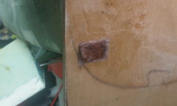
And then sanded them down so they looked like this:
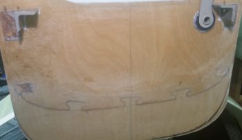
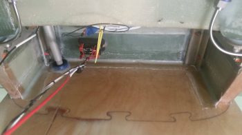
I then sanded the edges of the interior Hell Hole BID tape layups, and worked on the bottom longeron to firewall corners a fair bit. As you can see, the SD-8 Alternator relay and aileron control tube are looking ok.
I then did a quick test install of the engine mount on the firewall to ensure my efforts were all for a good cause! Actually, the quick test fit came after a half hour of me chamfering all the engine mount bolt holes on the firewall extrusions, then taking a file to the engine mount to clean up the rough edges on the bolt holes.
The engine mount fit well, although I noticed that the lower right engine mount stub was gapped vertically with the lower right extrusion about 0.030″, and the left the same at about 0.020″. I think there’s enough flex in all this that they can be cinched up fine without any undo stress, but it is interesting how these things appear after the fact.
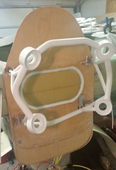
Here’s a shot of the left and right side test-fitted engine mount.
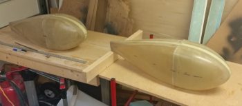
Early evening I was finally able to initiate operation 3-DAY BLITZ on the wheel pants. I got the wheel pants out and put the halves together on wheel pant #2.
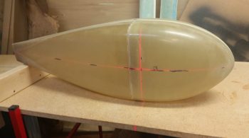
I then rechecked the alignment using a laser crosshair on wheel pant #1.
After I got all the axes aligned, I then taped up wheel pant #1 to secure the sides from moving (the sides are so tight fitting that they aren’t going anywhere anyway). After spending a good bit of time finalizing where I wanted the screw mounting holes situated, I drilled some 1/8″ holes where the screws/CAMLOCs will go and then Clecoed the holes.
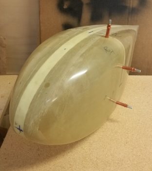
Here’s a shot of the aft side of the left wheel pant.
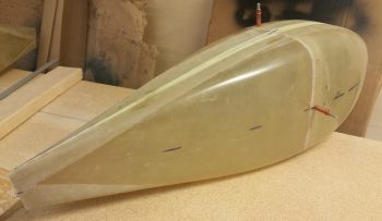
I then aligned, drilled and Clecoed the second (aircraft right side) wheel pant and then snapped these shots:
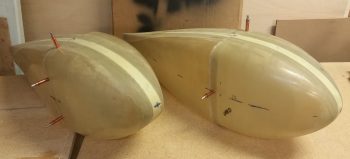
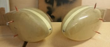
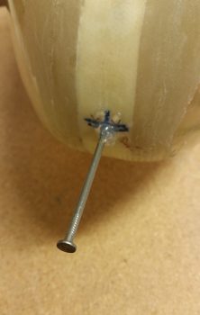
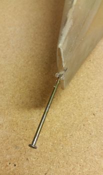
I then drilled a small hole in the CL front and aft of the wheel pants and placed 16 penny nails in the holes. To ensure the nails stay aligned, I hit them with some hot glue.
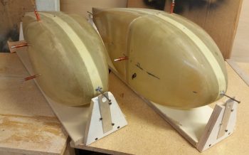
I then finished making the mounting jigs for the wheel pants. For the jigs I’m going with the Wayne Hicks’ style and have screwed-on adjustable elevation tabs both fore and aft on each installation jig.
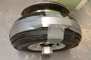
After ensuring the main gear tires were full of air (70 PSI) I then taped up a 3/8″ foam piece on the top of each of the wheels to serve as a spacer to keep the wheel pant from rubbing on the tire after the pants are installed!
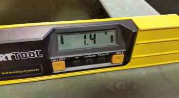
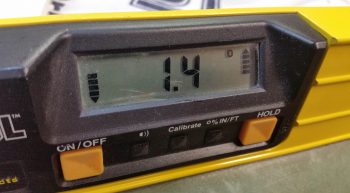
I also set the fuselage at a 1.4° nose up angle as you can tell by the right longeron (left) and the left longeron (right).
Tomorrow I will continue forward with my 3-DAY WHEEL PANTS BLITZ!