
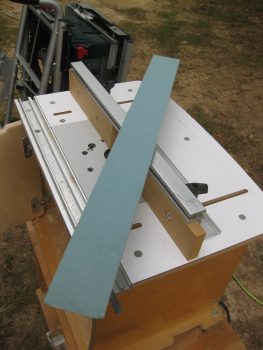
Technically I started off today working on the engine mount extrusions, but for a better flow of this post I consolidated them towards the end. So to make it EZ, I’ll say I started out by pulling out the Big Dog . . . literally, my Big Dog router table from the outside shed. I went through the trouble of pulling this sucker out since there’s simply no way to get the radius I want on the top armrest pieces (and to match the pre-existing radiused edge) without using a router table.
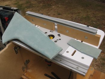
I set up the router table to route a small scrap piece of 3/8″ foam that was probably from the same originally piece as my side consoles since it has a ply of glass on one side. I would have actually preferred to put the glassed side of this scrap piece on the inside of the left armrest and had fresh foam on the outside, but the way the scrap piece wass shaped I had to radius the side with the 1 ply of BID on it.
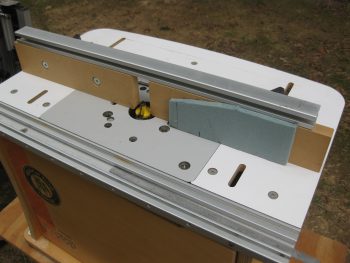
Here’s the end result. Sooooo EZ with a router table!
Now, me being not one to waste a good power tool while I have it out, I pulled the front left armrest pieces out and raidused the top piece of that.
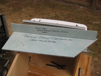
Here’s the long, narrow top piece of the front left armrest console.
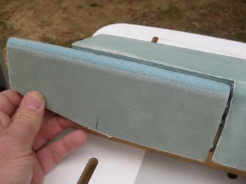
And here’s after I rounded over the edge.
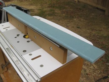
And a quick mock-up… looks good!
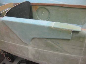
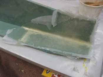
With nothing left to router, I put all my tools back in the shed and got busy glassing my newly rounded extension in place on the GIB left console. I micro’d the piece in place & then used 1 ply of BID. Remember, I’ll add a complete other ply of BID to all of this when I glass in place during its final install.
If you’re curious why I needed to add this piece back in place, it’s because I had originally thought I would put my GIB throttle quadrant right there. Well, first off the position is way too far aft… so my estimated positioning was way off. Secondly, after flying in Marco’s bird and having a few rounds of discussions at RR, I decided to forego installing an aft throttle quadrant to simplify my build and save weight & complexity.
Finally, if you’re wondering why I seem to be making the front of the left arm rest longer… I am. Another benefit of having experienced flying in the back of Marco’s plane is that things that may seem like they’ll work in planning (like my original positioning of the throttle in the back) simply don’t. In Marco’s Long-EZ he has a PTT button on the front face of the left side armrest. I can’t use it because I just can’t reach it. With the tight quarters in the back seat, I can’t bend my hand around to hit the button. So, in my plane I’m going to extend the left side GIB armrest a few inches forward and see if that does the trick since I do think that’s a great place to locate the GIB’s PTT button.
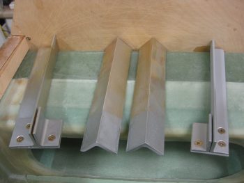
Ok, earlier in the day I cleaned all my engine mount extrusions with Acetone, and then gave them a final wash in Simple Green. Once dry, I painted just the ~1.6″ tips of the 2024 aluminum extrusions with a high end silver paint that my buddy –who is an auto body guy– let me borrow a while back. I did this to protect the part of the extrusions that are firewall aft (engine compartment) and to simply make them look a little snazzier than the Alodine look.
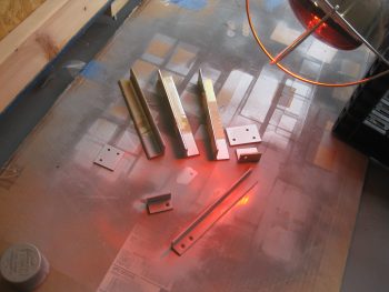
Wth the 4130 engine mount extrusion, I primed all the individual parts and then hit the last ~1.6″ with that silver paint. Clearly I’m not concerned about the firewall forward areas on any of these, because the top ones will get painted with the cockpit interior, and the bottom ones will be buried away in the hell hole.
I have to say I had a total brain fart and used packing tape on all the aluminum extrusions when I painted them. What do you get for trying to be too snazzy? An hour of using Goo-B-Gone to get baked on tape off your extrusions!! What a waste of time, and a hard learned lesson in finding out what material in the known universe that packing tape actually sticks to!
I then took a few minutes to sand the Spruce WA16 wedges to their final shape and round over the top edges just a hair in prep for glassing these into place. [I then spent a good 45 minutes cleaning all the bondo off the top of the CS spar. I chiseled the bigger chunks away be hand, then sanded the remaining bondo remnants off].
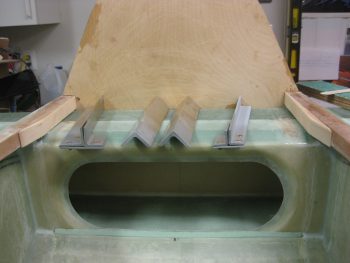
It was too late to start working on the canard (since I would have to move the wings out of the shop) so I started back working on the tool box a bit. First, I sanded the micro corners and then glass adjacent to the interior aft corners on both sides. These corners will each get a 1-ply BID tape. I also glassed a couple of spots in the middle areas of the inside on the back wall, since these will get reinforce layups to beef up some areas on the back side in order to mount it.
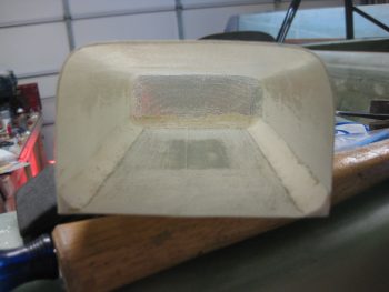
After taping up the tool box, I tried to use some urethane foam to make a rounded over top cover, or lid, but the foam wasn’t strong enough to handle what I needed it to do.
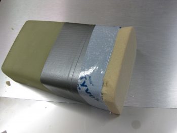
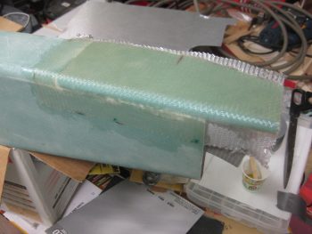
So I punted and simply taped up the top . . .
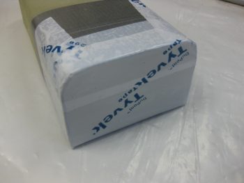
. . . and threw 4 plies of glass on it. This should work fine, but if not i can always redo it. I set it up to cure upside down so gravity would pull the wet lid glass straight down against the tape on my melamine working board, thus giving me a straight lid (if it works!).
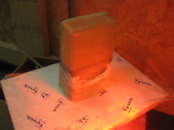
I then pulled the peel ply and knife trimmed the layup on the top extension for the GIB left side armrest. I did note that there was one delam right at the junction of where the new foam was micro’d in, so I’ll have to inject it with some epoxy.
I’m getting the hint that when foam is set in place with micro, it appears that if I put it under the heat lamp it off-gasses and then causes a small dlelam right at the micro’d foam junctions. That’s exactly what happened when I glassed in yet another piece of foam to the side of left side GIB armrest. There’s another delam bubble that I’ll have to contend with…. I guess I’ll get my money’s worth out of the syringe tomorrow.
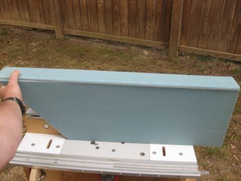
This is the last extension that I’m planning for the left side GIB armrest. I will shape it and glass the exterior side, and then I should be pretty much done with it until later when I assess whether I’ll mount a front plate or not for a possible PTT button.
This is pretty much the end of my clean-up tasks to knock out the “low hanging fruit” items. I will be doing some layups, etc. on the tool box, but I will be quickly transitioning my focus to finalizing the canard & elevator mounting from here on out.