Yes, I’m calling Chapter 8 completed! I may hold the record for the longest completion time for Chapter 8 in the history of canard building, but oh well! There are a few more nitnoy cosmetic things that need be taken care of, but structurally & functionally the components for Chapter 8 are finished!
I started off today by pulling the few bits of remaining peel ply from yesterday’s BID tape layups on the lower seat back. I then took the orbital sander to the seatback to help clean up the mess I had made during that gunky, sticky, tacky layup yesterday. Some days it just seems like you’re nothing more than Pooh Bear with honey stuck all over you, and that was this layup for me yesterday!
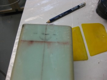
I took some measurements for the final BID piece that would make up the final layup on the lower seat back install. I had to go to the cutting table to lop off a piece large enough for this layup.
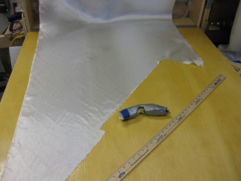
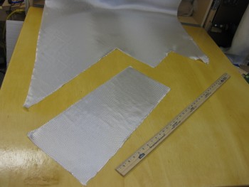
I pre-pregged mainly so that the line on the bottom edge would be fairly straight across, and would remain that way as I tugged and pulled on the layup around the curves on top. I figured it would also help in dealing with the oval hole in the center of the lower seat back.
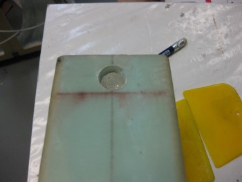
The pre-preg did seem to help a great deal when I cut out the BID to make a smaller hole in the middle of the oval shaped hole.
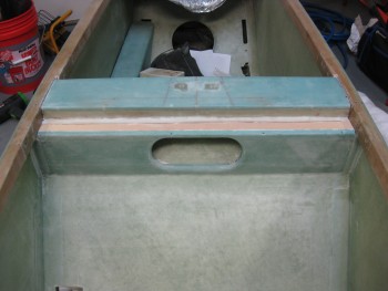
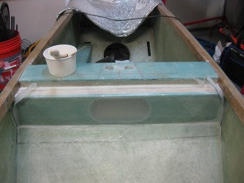
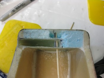
Also, in the pic below I’m ready to remove the plastic, and after shoving the glass into the upper corners at the glass shelf and longerons, the plastic easily just peeled right away.
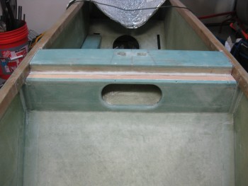
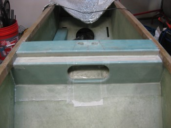
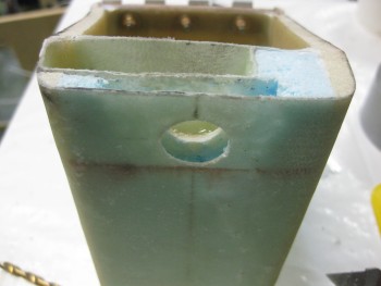
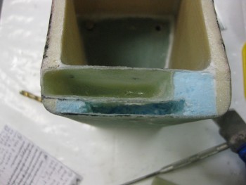
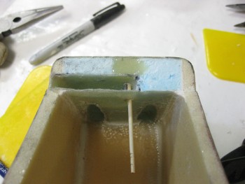
And here’s final layup of the lower seat back piece!
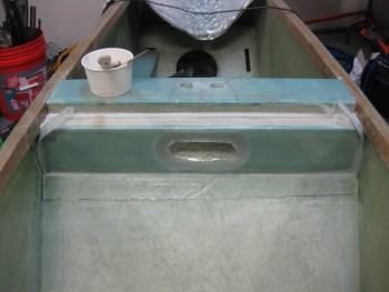
I did spend about another hour peel plying this layup, with my main concentration being on the edges of the oval hole. To help keep the glass to stay in place on the edges of the hole, I poured some of the epoxy I had on hand into another cup and threw in some Cab-O-Sil. It seemed to help, but the peel ply seemed to help a lot as well to keep the glass in place.
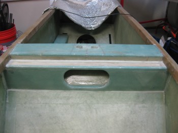
Here’s a view of the finished top cross bar notch.
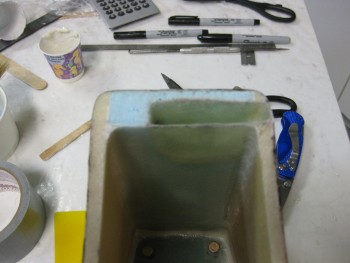
I then set my sites on installing the cam lock into the headrest. Once I determined how the lock was going to sit inside the headrest, I started whittling away the foam to create a channel for the lock arm to rotate into… and for the lock body to sit in as well.
I didn’t want to make the aft inner wall too thick (for clearance of the lock mechanism), so I laid up my first ply of BID so that it covered only the floor & aft wall of the channel.
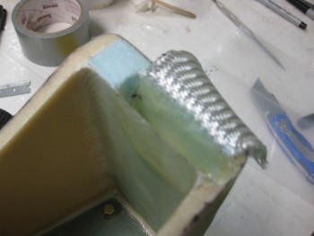
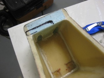
Then I added a ply of BID that covered the floor of the channel and all 4 sides.
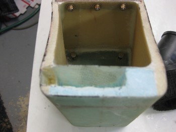
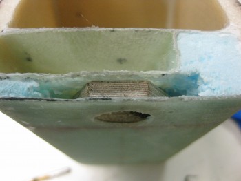
And to keep the flow of this step, I jumped ahead with the out-of-sequence pic below to show the finished lock channel layup.
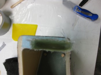
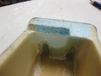
I pretty much had to do the mirror image on the upper headrest piece, since the lock arm would swing up into the upper headrest to snag the lock pin.
Thus, again I made a decent mess by carving out some more foam.
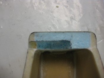
I then marked the install location for the cam lock on the lower headrest piece.
And drilled the 5/8″ hole.
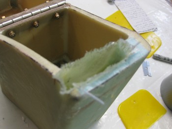
I then dug away more foam to create another channel between the very aft headrest wall, and the aft wall of the cavity that I had just created for the lock swing arm.
I used a scrap piece of 1/4″ Finnish Birch plywood & drilled a 5/8″ hole in that as well. The plywood will serve as a reinforcement plate for the lock, whilst all of it will be embedded in flox inside the new cavity I created on the aft headrest wall.
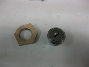
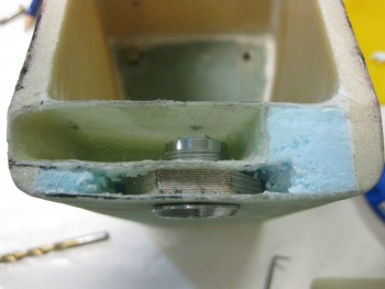
I dry fitted the plywood lock reinforcement plate.
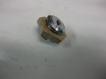
And also dry fitted the lock.
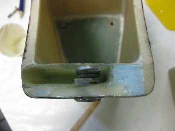
Now, not shown in these pics is the thick black line on top of the lock to ensure it got placed upright in the mounting hole with the lock slot vertical when it was locked. The cavity for the lock swing arm however was just a hair too angled on the outboard side, so the swing arm didn’t sit down all the way. Well, somehow in working the install, I somehow lost site on my lock orientation line, and when all was said & done . . . oh, and FLOXED . . . I had installed my lock [again, IN FLOX!] into the headrest 90° from where I had intended to set it. So my key doesn’t align with the position of the lock arm.
Oh, well. Worse things have happened, and often minor screw-ups like this turn into fun war stories later on. At least I still have vertical and horizontal key positions, versus some random funky angle!
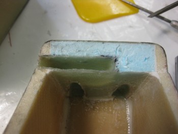
I then turned back the upper headrest to mount the lock pin. I cut off some uber heavy duty wire (I don’t remember what this stuff is for, but it may as well be a roll of steel rebar!)
The one bad thing about having a roll of really strong metal “wire,” is that when you cut it, it’s still curved! I spent about 20 min trying to get the curve out, and finally gave up when it was real close to straight.
Although I very carefully measured & prognosticated where the lock arm would hit the lock pin, I was off just a hair and had to move it over about 0.065″. To keep the lock pin in place in the now oval-ish hole, I used a drill bit. Then, after multiple, multiple trials of locking the headrest, I knew that the lock pin was in the right position. But before I could whip up some flox to secure it, I had to swap out the drill bit for a disposable and embed-able toothpick.
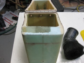
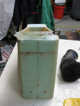
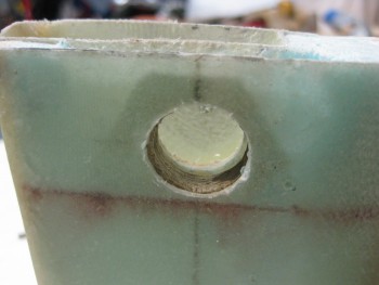
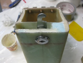
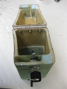
Here she is all floxed up.
And the whole headrest assembly showing some of my work for the day.
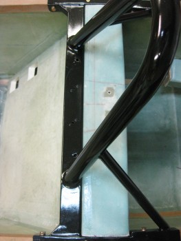
As the flox on the headrest lock pin was curing, I re-mounted the roll bar assembly, using all bolts & screws to ensure nothing had gone majorly wonky from glassing the lower seat back assembly. I did have to do some sanding & shaving in the left corner of the cross bar shelf, but after a little bit of time the roll bar slide into place.
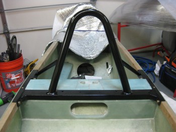
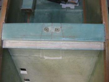
Here’s a long shot view of the glassed lower seat back & the cross bar assembly.
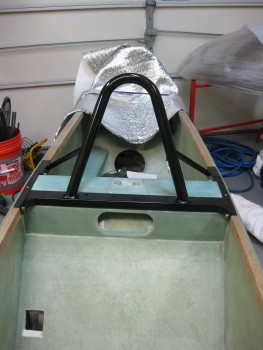
And I top level view to show the alignment of the lower seat back with the cross bar (the pic is offset just a little).
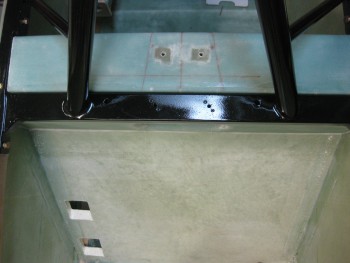
And the final shot of the evening shows the gap between the cross bar and the seat back shelf