
I’m taking a slight detour after I evaluated the gear fairing install requirements (see below).
I started out today by sanding down the sides of the axle mounting face on the lower right leg.
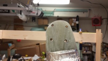
I then floxed the edges of the right lower gear leg axle mounting face and then mounted the right heat shield onto the gear leg. Before mounting the heat shield I waxed the back side of it to make it more easily removable once the flox cures.
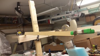
After I mounted the heat shield, I clamped on a straight piece of wood & dialed in the toe-in for a final time to let the flox edges cure to create a nice solid base across the entire axle mounting pad.
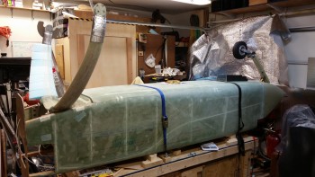
As I was contemplating installing the right side axle, brake assembly, and wheel, I figured I would check out the foam gear fairing I have on hand from Eureka CNC. On the Eureka CNC website there’s an example of the gear fairing kit install, but it’s for a Cozy. Well, the Cozy gear fairing foam pieces come in halves, whereas the Long-EZ gear fairings come as a single piece with a single slit across the thin underside of each piece. If there’s a way to get the gear fairing pieces on or off without cutting them, I honestly don’t see it. What this means is that I need to install the gear fairings before doing the final install on the axles, brakes, wheels & heat shields.
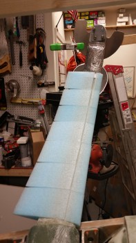
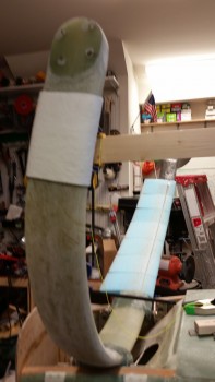
Here’s another shot of the right side toe-in setting. As for the gear fairing shown below, there’s one more piece that I wasn’t able set in place due to the thickness of the Fiberfrax. When I do install that last fairing piece I’ll have to reshape the foam on the inside of the fairing piece for it to fit.
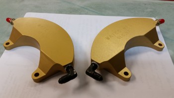
Once I finished my initial assessment on the gear fairing, I removed all of the left wheel & brake assembly off the left gear strut and then installed the 90° brake line fitting into the left brake caliper.
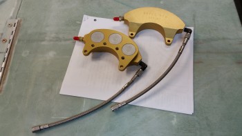
I then mounted the -3 Stratoflex stainless steel brake lines to check how they fit.
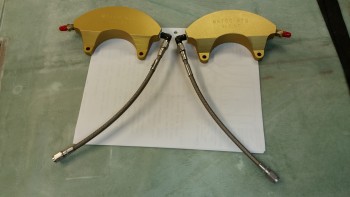
Then, probably more for my curiosity, I set up the brake calipers in the configuration that they would be in when installed on the gear legs as they are now on the inverted fuselage.
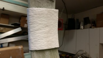
With the brake line fittings installed on both brake calipers, I then cut another piece of 1/8″ thick Fiberfrax 4″ x 10″. I then test fitted the Fiberfrax piece on the left side gear leg. I marked the area and then covered it with a good coat of RTV Silicone adhesive before putting the Fiberfrax in place.
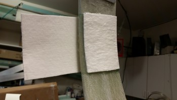
The pics below show the Fiberfrax set in place on the left gear leg.
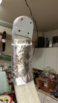
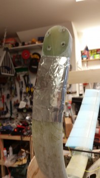
I then covered the Fiberfrax with foil tape.
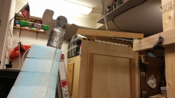
Although I don’t have the wheels installed, since I’m moving into a new phase on the main landing gear, I figured I would take a shot with the mini-“Straight Tower of Pisa” taken down.
Tomorrow I’ll be on the hunt for 7/16″ OD thin-walled tubing to mount inside the gear fairing to allow for installing brake lines, relief tubes, etc. I also need to determine the feasibility & cost of flaring the 3/16″ stainless steel brake line tubing I have on hand. If it doesn’t seem doable in the very near future, or is too costly, I will most likely run Nylaflow from the aluminum brake lines ending in the hell hole to continue down the gear legs.