
Today –while the canard epoxy cures– was about research and getting reacquainted with my electrical system. My specific interest was in figuring out what components, electrical & otherwise, that I was going to put into the nose.
Now I know a lot of my contemporary building buddies would whip up some awesome looking CAD diagram with exact dimensions down to 3 decimal places that looks like an engineer’s dream, but me being a former military “Powerpoint Ranger” and certified neanderthal, I simply added a slide depicting my thoughts on this matter onto the end of my ongoing notes for the nose build.
Again, this stuff is really just a mental thought jogger on what will most likely go into what areas in the nose, and get me thinking if there is any pre-actions or prep I can do as I build the nose. Some of the components I ID’d will be in the nose area, but aft of F22: OAT probe, static ports, buss fuse housings, etc. In addition, on many of the components I had to look up in my notes, emails, websites, install manuals, etc. to either confirm or research further why and how they were getting installed where.

Now, I mentioned CAD earlier, so speaking of CAD: The CAD program I was using to create my electrical diagrams was NanoCAD, as recommended by Bob Nuckolls in the AeroElectric Connection online forum. This was a great CAD program for electrical diagrams primarily because A) it was what Bob used to create all of them, and B) it was FREE! Unfortunately, my version of NanoCAD is no longer supported and apparently NanoCAD is now on Version 7, which costs a decent amount of money now to buy.
Well, no worries since I have TurboCAD, which I happened to purchase while I was in Tampa, Florida. But I didn’t have it loaded up on my desktop so I ended up spending a good half hour loading up TurboCAD and familiarizing myself with its features before I could open up any of my electrical diagrams. Why? Well, in a series of typical events, I had taken all the hardcopy printouts of my electrical diagrams down to my buddy Marco’s house while I was on leave from Qatar in March 2014, forgot them there, and haven’t been back to retrieve them yet . . . mainly because every time I go to visit him he puts me to work building HIS Long-EZ! HA! (Click here for the real story . . . )
Thus, to be able to make my annotations on my electrical diagrams on an actual sheet of paper, I had to be able to open the darn files to print them, which I am happy to report that I am now able to do.
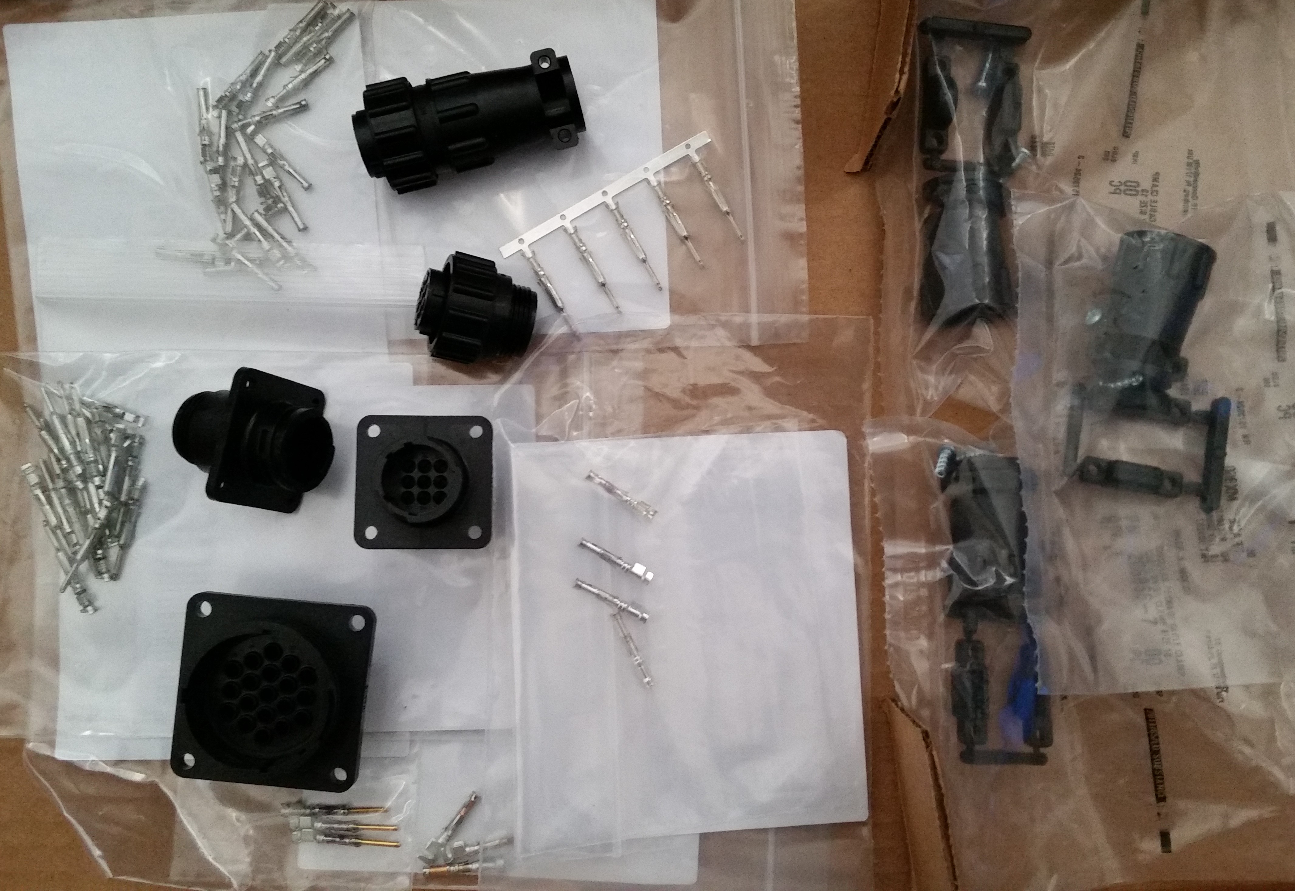
In line with my reviewing my nose electrical components, my main preparation is in getting the nose gear actuator wiring sorted out to test it. I had planned on going over all my electrical stuff today since the epoxy was still curing on the canard and also, in part, because my AMP CPC connector order from Mouser was scheduled to be delivered today, which it was.
I checked out all the goodies from Mouser and pretty much solidified my plan for the wiring & connections for the nose gear actuator system.
Tomorrow I plan on a good final sanding of the canard top surface before I apply a couple of coats of primer on it. In addition, I’ll most likely cut the UNI for the elevators and start planning out a refined elevator build schedule. Who knows, I may even get the nose gear actuator wired up & tested out.