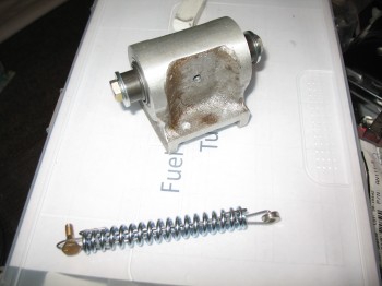
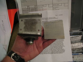
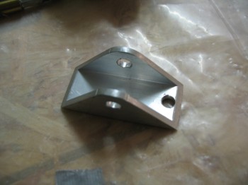
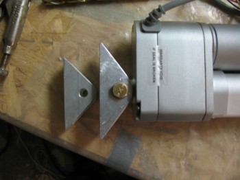
Today I received the NG6B from Jack Wilhelmson. The NG6B is a “special modified NG6A with threaded internal bearing spacers with two AN5-15A bolts. For use when the AN5-41A bolt cannot be removed without cutting or drilling holes in the fuselage.” (The spring in the pic just below is the spring that goes between the rudder cable & the rudder/brake pedals–one on each side. I had the springs on hand, so I made this up. There are some ways to configure the rudder/brake system so it doesn’t require this spring which I’ll research out more . . . but just in case!)
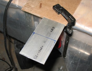
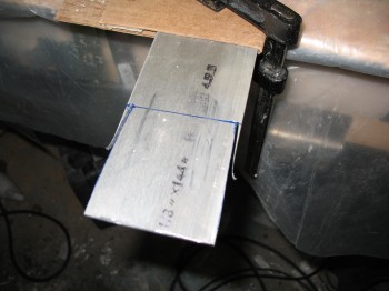
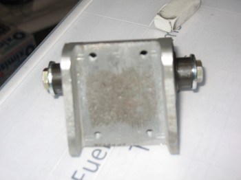 Now that my NG6B is here I can cut my 1/8″ thick 2024 aluminum stock to make the NG5, which is simple the plate opposite the NG6B that sandwiches the Nose Gear Strut & gives the screws a strong surface to compress against, like a clamp around the strut vs using only the fiberglass of the gear strut.
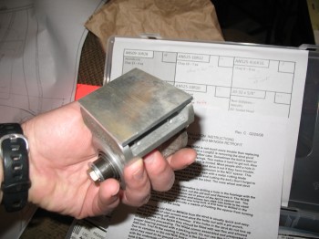
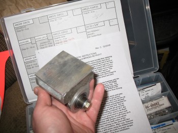
And here’s how the pieces look together. Of course when mounted there are 4 screw holes in the NG5 plate & the nose gear strut sandwiched in between the NG6B & NG5.
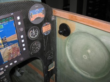
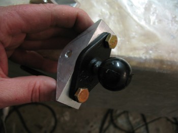
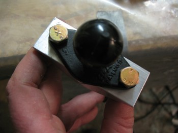
Next, I grabbed the 2 RAM ball mounts that I had just received from Aircraft Spruce to mock them up. My initial plan is to have one RAM ball mounted to the Right-side fuselage wall in the hardpoint I embedded just aft of the instrument panel–as I have mocked up in the pic below.
The other RAM ball mount will be mounted on the center instrument panel post. The bolts used to attach this RAM ball mount will also serve to attach the bracket on the pitch trim actuator for my Davenport pitch trim system (also shown in the picture below is my Andair fuel valve).
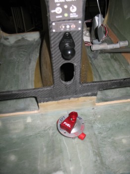
 The screw used in the above picture is a AN3- (3/16″) vs an AN4- (1/4″) screw/bolt that will be used to attach the RAM mount & pitch trim actuator bracket. As I attempted to drill the 1/4″ holes on the original pitch trim actuator bracket I quickly noted that I had an issue with the bracket being too short.
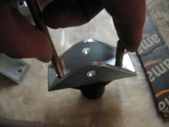
 Although I got one hole drilled, and it looked like it could work, the hole wasn’t actually equidistant from the center meaning that the other hole would be even further from the center line, and actually into the angled edge. In short, I had to make another bracket to make this design work. So I cut another, slightly longer bracket out of 1″ x 1″ 2024 aluminum U-Channel.
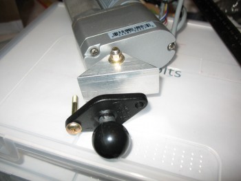
 I drilled the 1/4″ holes & test fitted the RAM ball mount.
 Below is a comparison between the original bracket & the new one that I just made.
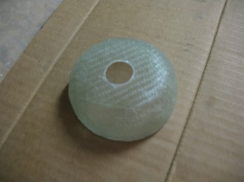
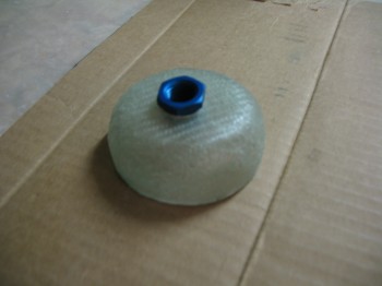
 Now, with the new pitch trim bracket completed I moved on to my Chapter 21 – Fuel Tank Vent Manifold. I drilled a hole in the top (again, about 21/64″ in diameter) of the second cap and then test fitted the AN912 bushing.
 I then marked the first 2 (out of 4) side positions & drilled those holes as well.
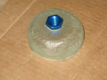
I then test fitted the two AN912 bushings into the side of the manifold, placed the new end cap in place and prepped all of the bushings & glass for floxing.
I floxed in 2 AN912 bushings into the side of the manifold & floxed one AN912 bushing into the cap. I set them in front of the heater to cure.
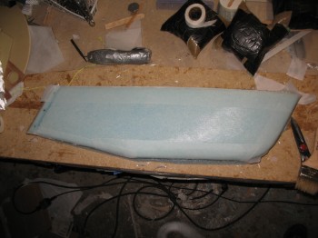
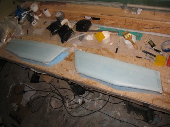
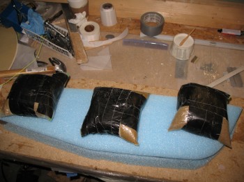
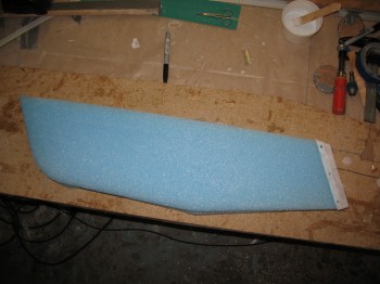
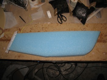
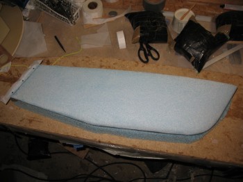
Finally, I moved onto my Chapter 20 – lower winglets build. I finished shaping the Right lower winglet.
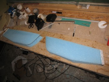
I then shaped foam bases (from the original foam that the winglets were cut from & encased in when they were shipped to me) to mount the winglets to during glassing so that they would maintain their shape. I screwed the foam bases to the work bench with 3 wood screws.
I mounted the lower winglets to the foam bases using 5-min glue & weighed them down while curing.
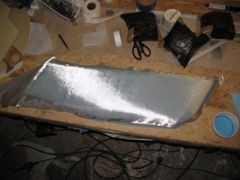
With the winglets mounted to the bases, I prepped them for glassing. I vacuumed the winglets & tacked in a 1″ peel ply strip along the TEs.
I the micro’d the foam, working on only one winglet at a time.
I glassed each winglet using 2-plies of UNI at ±30° bias.
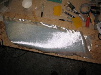
I then peel plied the edges after laying up the glass plies.