
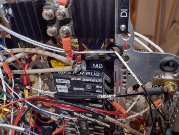
Another 2-day post here… where I finally got the E-Bus inventoried, fuse values adjusted (as per respective component manuals), some items moved, and some items removed. Let me tell you, the E-Bus was a heck of a lot busier to finalize than the Master Bus was any day.
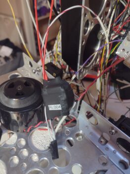
I also finally got around to wiring up one of my last (but not THE last of course <wink>) relays on this bird: Relay #4 (RL004). This relay simply keeps the power off for the Canopy/Gear Warning System (see that big ‘ol piezo buzzer in the pic??) until the engine is started. Then all the lights can start flashing and the horn can start blaring that the canopy is open . . . etc.
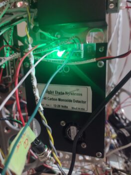
 I also spent a good bit of time really digging into the GD-40 CO Detector manual. At the end of the manual it states that these things have a life of about 5-7 years, although often make it to 10 years before the sensor has to be renewed and calibrated (yes, question is: Is that shelf life or operating life?). Apparently (as I don’t remember!) this thing ships with a combined green/red LED that is used to run self-tests and display any major issues with the unit.
I wanted to run these tests in case I needed to ship the detector back to the manufacturer for a refresh before I start flying. But speaking of flying, this thing passed all the self-tests with flying colors… literally, as in this steady green light during normal ops means that there is/are no issues. Rock ‘n roll!
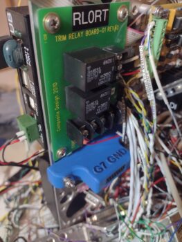
 Day 2, after about a good final hour on the E-Bus, I got busy doing the final build on the G7 Ground Bus. I made my final tweaks in CAD and kicked off the 1 hour 45 minute 3D print for the mounting bracket.
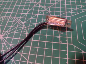
I then went out to the shop to grab some 14 AWG wire, cut two lengths of it, and then proceeded to solder those wires to the aft side of the female DB15 D-Sub connector. After the solder cooled, I did a continuity check on every socket with each wire lead. All good!
 Once the G7 ground bus mounting bracket was through printing, I cleaned it up and hot-sank threaded brass 4-40 inserts into the inside face. This allowed me to install the male DB15 connector first, with the wire-soldered female DB15 after that, and secure them both as a pair with 4-40 screws.
As you can see, I then labeled the wire pair and crimped a ring terminal for connecting it to the G4 main ground bus.
 Now, the 4-40 threaded inserts worked very well, but the holes on the outside —where I intended to hot sink 6-32 threaded inserts— were a bit too narrow in diameter and the resulting excess plastic really gummed things up. I tried to gingerly use a 6-32 tap to clean things up, but it grabbed the threaded inserts too tightly and broke them loose from the plastic holes… so I just pulled them out.
I then re-tapped the plastic holes and rounded up some washers and Nylock nuts. However, I had to go down to the Lowe’s Aviation Department to pick up some 1″ long SS screws to get this thing to final install.
The threaded insert issue notwithstanding, I’m very happy with how the install went. In fact, I like this method of installation better since the washers and nuts provide an even more secure mounting.
 Here we have the double-wires going to the G4 main ground bus on the Tri-Paragon (and no, STILL have not gotten to cable management… yet!)
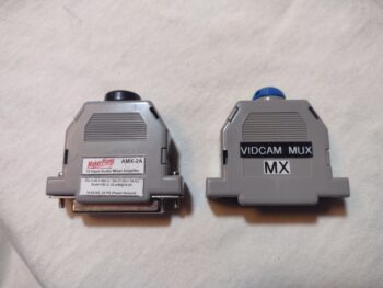
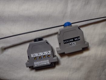
 I also spent another 5 minutes in CAD finalizing a small dust cap that gets clamped into place between the two back shell halves on the Video Camera Mux, that the 4 individual video cameras plug into. My other twin sister unit of this style of small-footprint electrical device is the 10-channel Audio Mixer, that I put in each pic. The black dust cap on the audio mixer is where I got the idea to fill that hole in the backshell case of the VidCam Mux.
Note that I added a slot for a zip tie in my 3D printed dust cap just in case I want to use that to help secure it onto the Tri-Paragon (pic 2).
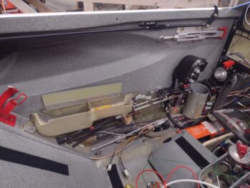
The weather was finally a tad bit warmer today (mid-50s) and in prep for installing the Tri-Paragon in the bird (planning to start tomorrow) I installed a couple of wires, labeled a few more, did a thorough scrubbing of the quite-dirty P4 connector (both sides), and then removed the left armrest to expose the handful of micro-switches on the throttle quadrant that will need wired up.
 Back in the house I did some more exciting administrivia for about an hour, in part cleaning up the numbering of my panel top row indicator lights that I’ve been playing musical chairs with the past few weeks. I also had to evaluate and draw up a new circuit diagram to add those lights into the current wiring schema.
Yes, hoping tomorrow proves to be a significant milestone with the Tri-Paragon actually mounted inside the airplane!