
Chapter 22 – Antennas Page
In addition to the main electrical page that is ordered chronologically, I’ve added a separate web page specifically for antennas. Please note however that antennas embedded in flying surfaces (wings, winglets, canard, etc.) will be shown on those build pages.
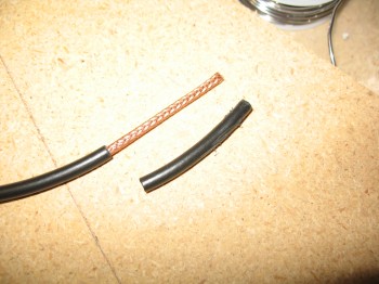
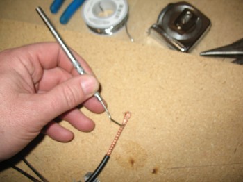
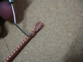
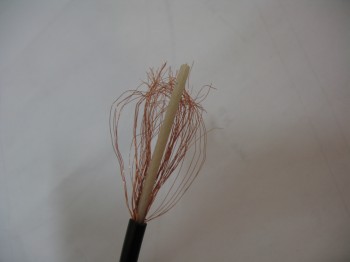
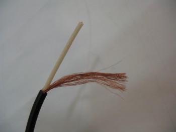
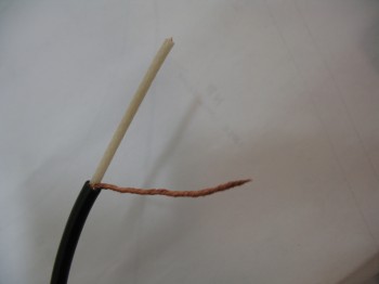
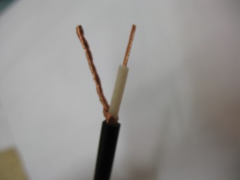
9 May 2013 — The following pictures show the general steps I take to make an antenna using Jim Weir’s design. I will say that going back and reviewing the instructions on how to make these antennas, I should have probably cut the leads a little shorter that attach to the copper foil. Of course I think the antennas will still work fine, they’re probably just not as optimized as they should be for Tx & Rx.
[Note: Please see Chapter 10 – Canard for actual antenna installations in the Canard, Chapter 19 – Wings for actual antenna installations in the wings & Chapter 20 – Winglets for actual antenna installations in the winglets.]
•••
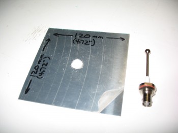
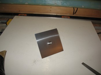
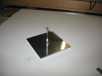
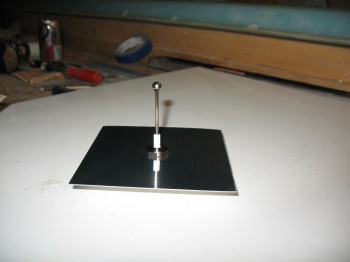
17 May 2013 — Today I built my transponder antenna. I had already collected some data . . . read Jim Weir’s stuff, and then ran across some transponder antenna info from Dynon. After a little bit more research, I decided to follow Dynon’s recommendation to go with a square 120mm x 120mm (4.72″ x 4.72″) metal plate for my transponder antenna. This allows for a wider range of frequencies vs a round plate. Also, this size plate is optimized for transponder frequencies. I used aluminum of course for weight, 0.025″ thick.
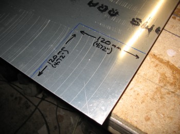
I cut out the plate & then drilled a 1/2″ hole in the middle of the plate, chamfered the hole & then installed the TED transponder antenna.
[Operational Note: I will no longer be using the transponder antenna that I constructed above, but rather the L-2 antenna transponder antenna below]
•••
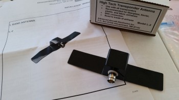
14 January 2016 — I started off this morning with a visit from the UPS guy delivering my Christmas present: an L-2 Transponder Antenna. I decided I wanted one of these vs the old standard transponder antenna (the one immediately above this one that I constructed back in 2013) after I talked with Nate Mullens about his installed L-2 antenna & he highly recommended it.
•••
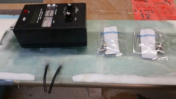
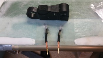
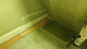
27 January 2016 — Before the canard went back up on the wall for storage, I wanted to terminate the canard VOR/LOC & glide slope antenna cables with connectors and check the VSWR.
The first step in terminating the antenna connectors was to get down to the center conductor of the RG-58 cable by removing 1/8″ off the end of each cable.
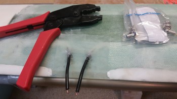
I then crimped on the center coax pins using the RCT-2 crimper (B&C) shown above.
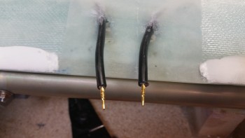
I then slipped on the ferrules.
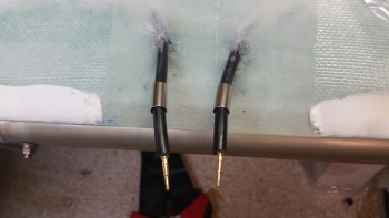
I then stripped away another 1/2″ of the outer jacket using a coax cable stripper. This exposed the cable shield braiding.
I then slid the main connectors into place, slid the ferrules forward over the braiding and then crimped the connector assemblies into place.
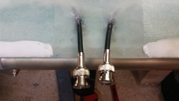
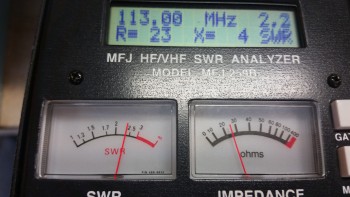
I then checked the VSWR of the VOR/LOC antenna using the MFJ-259B Antenna Analyzer, which read 2.2. A VSWR value of 3 or under is acceptable, so I’m very pleased with 2.2 VSWR value. Unfortunately, since the frequency of the glide slope antenna is in the 330 MHz range I couldn’t check the VSWR for that antenna on this meter, so I’ll test that later.
[Note: If you’re wondering what the heck VSWR is, check out Jim Weir’s article in the Dec 2013 issue of “Kitplanes”… where he explains it very well. Basically, Voltage Standing Wave Ratio (VSWR) shows how much energy that is sent to the antenna that’s off-resonance to the frequency actually returns back up the transmission line to the transmitter (radio) inhibiting efficient transmitting power usage. A theoretical VSWR of 1 would mean 100% of the radio’s power is being transmitted. A 2.2 VSWR means that on my VOR/LOC antenna I could theoretically transmit out with only 14% of the power reflected back to the transmitter (bad) while 86% of the power would get transmitted (good). A 3 VSWR means 75% of the transmitted power is good (meaning a 6 watt radio would only realize 4.5 watts out). Obviously the efficiency of your antennas directly effects the actual wattage available for transmitting. Although the VOR/LOC antenna only receives, I wanted to check its VSWR to get a general idea of the state of my embedded antenna connections, and brush up on my VSWR testing capabilities.]
•••
21 June 2017 — Today I 5-min glued the remaining center area –top & bottom– of the piece of German “PVC” pipe that I’m using as my antenna channel cover.
After the 5-min glue cured, I then got to work mixing up some thick micro, slathered it on each side of the channel cover, and then laid up 1 ply of BID over top of that. Of course I peel plied it after I was done with the layup.
•••
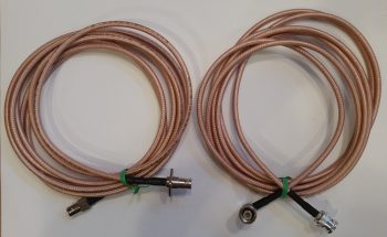
11 August 2017 — Today I received the COM1 and XPDR antennas that I ordered, terminated with the appropriate fittings. One more thing off the list!
•••
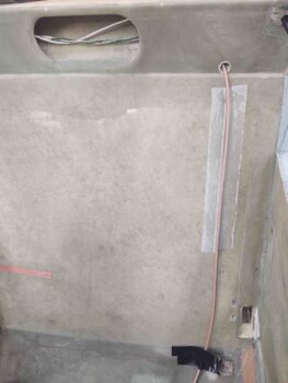
21 November 2020 — One of the many things I’ve pondered over the past few years was exactly how to run the GNS-480 GPS antenna cable from the panel mounted GPS to the pilot headrest-mounted GPS puck.
Here’s a shot of the GNS-480 GPS antenna cable when the pilot’s headrest is opened to access storage.
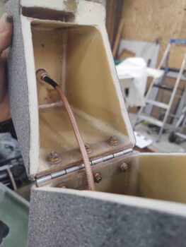
I finally decided that instead of punching through the back of the pilot’s seat at a low(er) point just to have the cable re-enter again towards the top, I would run the GPS antenna cable up the front face of the pilot seat bulkhead. I have it positioned so that it is right at the edge of the seat cushion. just barely covered by it.
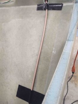
I don’t like making things inaccessible in case they need maintenance or repair, but I figured this cable is fairly low on the failure scale, so I simply glassed it to the front face of the pilot’s seat with a ply of BID. This is the first of a few piece of BID that will secure the GPS antenna cable to the front seat back.
•••
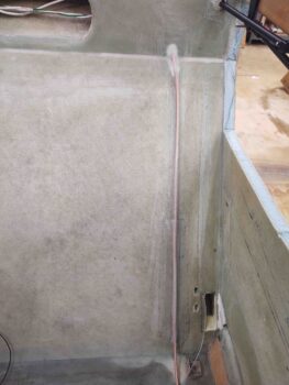
22 November 2020 — I got to work on pulling peel ply and cleaning up the final layups on the GNS-480 GPS antenna cable. Apparently I forgot to grab pics or report on my GPS antenna cable progress, but here it is in its final state before the cockpit gets painted.
Again, with MGS epoxy it’s hard to tell, but there’s a ply of BID securing the GPS antenna cable from the bottom of the pilot seat back bulkhead to the top where the cable enters the seat back structure/rollover base.
•••