Chapter 23 – Engine Build: Part 1
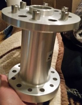
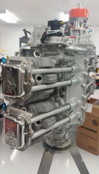
17 January 2018 — My Winchester, Virginia-based engine builder, Tom Schweitz, called today to ask me some configuration questions on the engine for the build next week. To make absolutely sure I was answering his question on prop flange bolt size, I pulled the prop flange to confirm. I figured since this a close-in objective, I would snap a pic of it so we can all get into an engine frame of mind….
•••
22 January 2018 — Today was all prepping for the engine build.
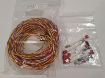
While collecting up parts and components for the engine build I finally took a good look at the GRT EIS4000 Engine Info System Connector B wiring harness that contains the wire leads to the engine CHT and EGT probes. However, after digging around in the box I didn’t find anything else other than what is pictured below, so I sent an email to GRT with the pic asking for clarification on just the exact CHT/EGT stuff I was supposed to get with the EIS4000.
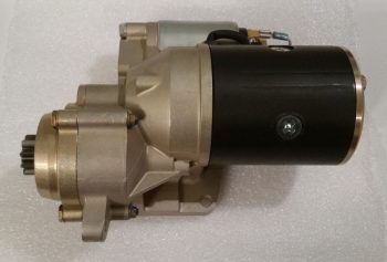
Since I haven’t taken pics of the shy B&C starter and its closest buddy –also shy– the B&C 40 Amp alternator, I thought I’d do so before they get mounted to the engine.
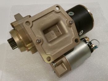 Now, both the Canard Pusher newsletters and B&C touted this starter as “lightweight” and maybe it is compared to other starters out there, but man, when I was dragging this and the alternator down off the shelf in the shop I thought…. that’s a lot of combined weight for the very aft point of the engine, no wonder Burt wanted us to hand prop these birds!
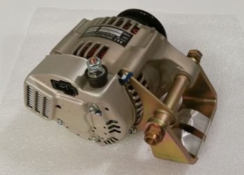
Here’s the shy twin: the B&C 40 Amp alternator. Looks like a quality piece of equipment . . . very robust.
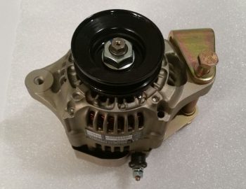 And one final shot of the B&C 40 Amp alternator before it goes back in the box to get mounted on the engine in the next day or two.
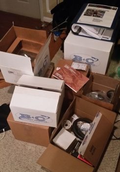
Finally, here’s my engine “kit” awaiting loadout into my truck. I wanted to wait until the morning to load the truck since that’s a lot of money sitting there …. so will keep it as safe as possible until necessary to haul it.
•••
23 January 2018 — Ok, let’s get started . . .
It was a dark & rainy morning (really) this morning when I loaded up the truck and I got on the road around 0630. The rain made the typically slow DC-area drivers drive even more slowly, so I got to the main A.E.R.O Engines office at Winchester airport just a hair after 0800. It didn’t matter though because the owner, Tom Schweitz was over at the engine assembly building across the airfield. So I drove over and met Tom, who then introduced me to one of his master engine builders, Frank.
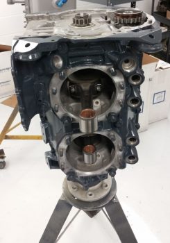
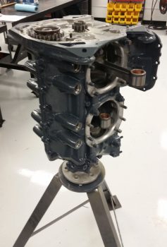
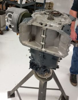
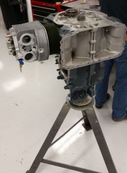
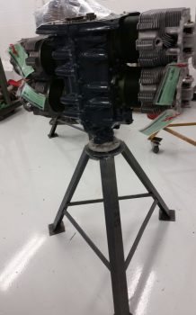
They showed me my engine with the crankshaft already mounted up in the crankcase on the build stand. Since there was some confusion over whether I should have 1/2″ or 7/16″ prop flange bolts, they installed a brand new 340 strokered crankshaft with 1/2″ prop bolt flange into the Lycoming crankcase that I had bought from Tom back in July 2013 (right before I went to Qatar for a year). [NOTE: There was a bit of confusion on my side as well, so when I sent the prop extension back to Sam at Saber Manufacturing to have 3/8″ prop bolt mounting holes drilled for a Hertzler Silver Bullet prop, I also had Sam drill out 1/2″ prop flange mounting bolt holes in-between the 7/16″ holes. In the end, it cost a bit more, but it all worked out and I can now use a lot of different props on a lot different engines with this prop extension]
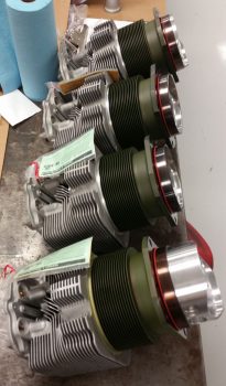
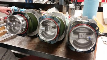
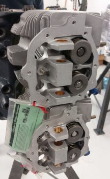
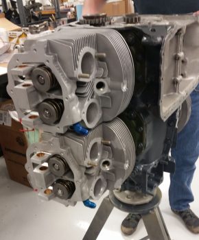
And here’s the 4 brand new cylinders and pistons, that come as a matched set for flow and weight. I had originally planned on going with tapered finned cylinders for weight reduction, but in the end decided against them since these below not only cool better (obviously more surface area) but if I ever have just one jug go bad on a trip, I can simply replace the offending cylinder with a common Lycoming/Superior/ECi vs having to track down a tapered fin cylinder (from Continental now since they bought out ECi).
The pistons are a standard low compression piston ~8.5:1 but when strokered the output is equal to 9.2:1 higher compression pistons. This configuration alone will typically dyno out at 185 HP. But add cold air injection and RAM air and it should result in numbers well over 190 HP, so I don’t need to thrash the cylinders with even higher compression pistons just to add a few more horses.
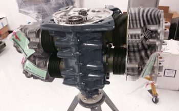
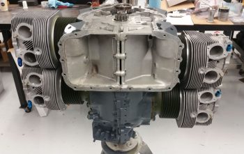
Luckily I grabbed a couple of quick pics of the crankshaft in the case and all 4 ECI cylinder/piston assemblies (above), because by the time I got out the door & back with a load of some of my engine goodies Frank already had one jug and piston mounted to the crankcase/shaft.
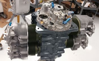
Here’s a look at the first jug in place on the crankcase.
And here’s another look at the cylinders with each respective piston inside its cylinder. This setup makes it much easier and faster to build the engine since there’s no messing around with wrangling oil rings to get the pistons into the jugs.
Again, another load of my engine accoutrements and yet another jug in place!
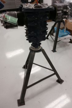 Here is Frank on jug #3 (I’m not going by cylinder #s, just order mounted).
And cranking down the myriad of bolts that hold these beasts in place. I have to tell you, the specialized tools this shop has made this job look REALLY easy!
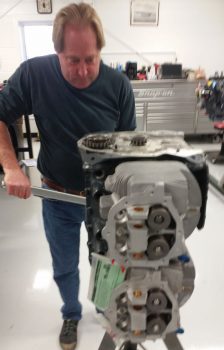 Here’s a closer look at the top of the valve springs and cylinder heads.
About the time I finally got my engine gear situated, cylinder #4 was in place with the bolts getting torqued to final specs. As bantering ensued, I was a bit relieved that the conversation turned to what color paint I wanted the engine, INCLUDING the cylinder barrels. We had a good laugh when I conveyed that I had been having some initial concerns over the odd color combination.
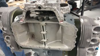
Here’s the bottom of the engine where the Superior cold air induction oil sump will get mounted. Unfortunately, we discovered that the one I had ordered from Tom got scarfed up on some other build, so Tom had to order a new one that won’t arrive until next week. Yes, for all you Air Force types: “Flexibility is the key to airpower!”
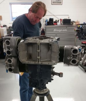
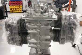
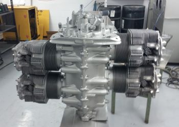
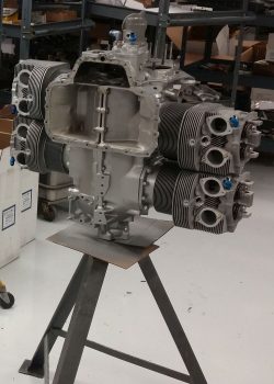
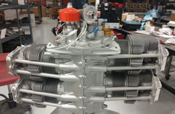
A longer shot of the completed cylinder mounting.
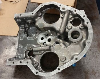
Frank then pulled out a somewhat raspy looking accessory case. He explained that just like the engine core, a lot of larger components get reused during builds, and that the cleaning/degreasing process actually makes them look a little rough . . . and thus part of the common practice of painting of the engine cases!
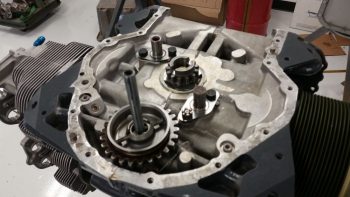
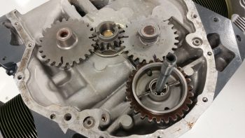
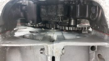
On the engine side, the two separate idler gear posts are placed on either side of the smaller oil pump gear. The larger gear towards the bottom of the screen is the camshaft gear.
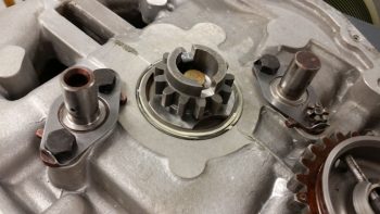
You can see on the idler gear posts the bend up tabs that are used quite often in lieu of safety wire.
Then the idler (“mag”) gears slip in over the idler gear posts and get marked and placed in relation to each other and TDC.
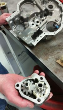
Frank then lubed up the internal oil pump gears and mounted the oil pump assembly into the accessory case.
Then applied some RTV-type sealant in a few spots around the crankcase & accessory case interface, threw a gasket on and proceeded to mount the accessory case in place.
A shot of the bottom bolt attach points for the Superior cold induction oil sump on the bottom of the accessory case.
And a shot of the gears inside the accessory case housing.
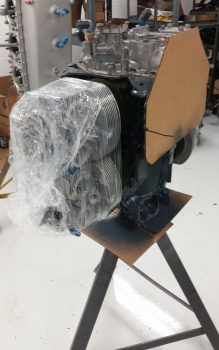
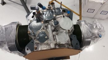
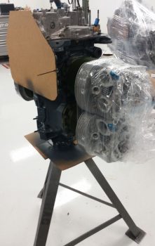
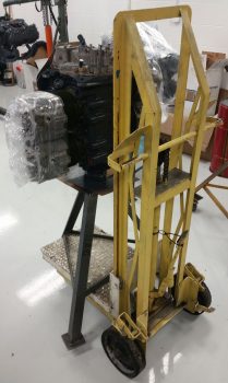
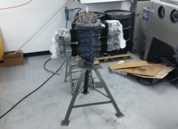
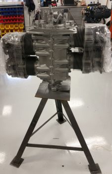
We then wrapped up the jugs and placed protective plates in place, including the large piece of cardboard on the engine bottom, to prep the engine for paint. In the background in the pic below you can see a large 6-cylinder Continental motor being built. I wasn’t overly thrilled with the blue/gray color (it wasn’t terrible, but I preferred a color that conveyed a bit more of “Formula 1 race car” and a bit less “tractor” to me), they didn’t have the high grade black engine paint on hand (they don’t buy it because Tom hates painting motors black!) . . . so, I went for that Continental silver in the background (anyone who knows me… and my truck, knows that I really like silver vehicles. So it worked out great.)
Another shot of the engine prepped for paint.
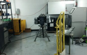
We then picked up the whole engine, stand and all, and moved it down the long building to the paint booth.
Here’s the engine in the paint booth ready for a makeover.
And here it is sporting its new sexy silver color… love it!
Again, in different light.
We found a couple of small spots that Frank missed, so back to the paint booth for some touching up on the paint job.
Again, love this silver . . . very nice (IMO).
We then got to work on the accessory case by mounting the 90° oil filter adapter.
Here’s another shot of the oil filter adapter. As a point of note, only the plate on the far right is real. All the others are simply covers to keep the paint out of the holes.
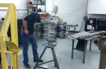
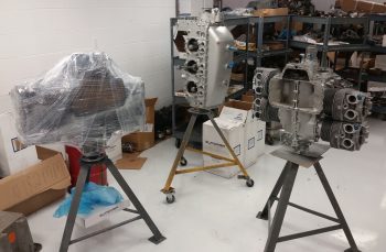
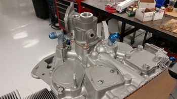 I took this shot just to show some of the concurrent engine builds they have going on… incredible. If you’re not sure, my engine is the one on the right…. (big smile).
A close-up of my engine build in progress . . .
We then installed the SD-8 backup alternator on the vacuum pad. This was done after Frank had installed all the valve lifters & tubes, valve rockers, and some outstanding Titan covers that Tom dug up (no painted “Lycoming” valve covers for me! <grin>)
Another shot of the engine build in progress.
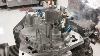
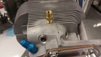
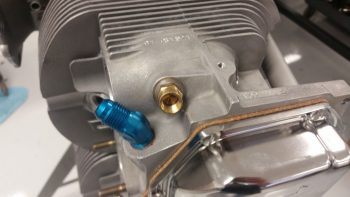
I then dug out my brass fitting insert that has a very small outlet hole and serves as the transition from cylinder head to braided manifold pressure tubing. Below the brass fitting insert you can see the hex plug that will get removed so the brass manifold fitting insert can be installed.
I then installed the brass manifold fitting insert.
Here’s a longer view of the brass manifold fitting insert and the mounted SD-8 backup alternator.
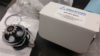
We then set our sites on the “mags.” I have to say it was an interesting environment because, although it was very loose and fun with the guys, they don’t do or understand the experimental world. The stuff I brought was all very new and a mystery for most of these engine builders (except for Tom…. thank goodness, since he often served as my “interpreter”). Thus, I double-checked the manual on the Electrair electronic ignition Mag Time Housing installation . . .
to ensure we got installed correctly in relation to TDC.
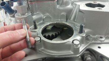
Since we didn’t require a Mag impulse coupler on either side, both sets of long threaded studs had to be removed out of the accessory case and replaced with shorter ones. In the pic below I’m holding one of the longer studs, with the shorter ones already installed.
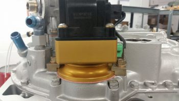
We then installed the P-Mag.
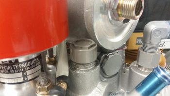
We then installed the Andair mechanical tach port cover.
Another wider angle shot of the population-increasing accessory case.
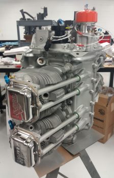
I took this pic below to show what it would like to view the engine from the side, as it sits in the aircraft.
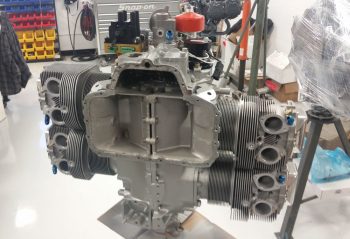
Another view of the bottom side of the engine.
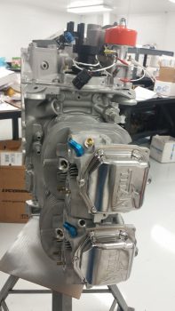
A side view . . .
A quarter view.
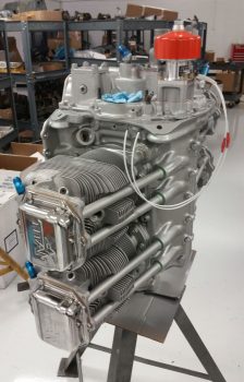
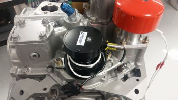
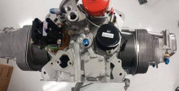
A slightly fuzzy shot of the increasingly populated accessory case, with the P-Mag, 90° oil filter adapter, SD-8 backup alternator and Electroair MTH all installed.
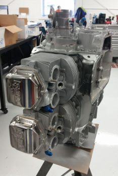
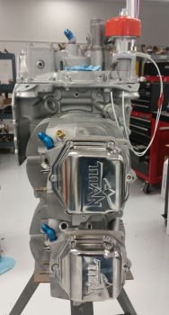
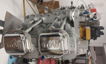
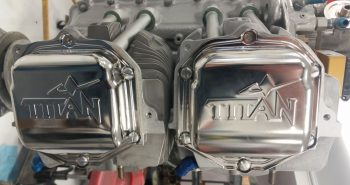
Here’s a closer shot of the shiny “Titan” valve covers indicative of the IOX-340S engines. Again, stylistically I’m glad that they had these on hand (as a very busy build facility for certificated engines they just don’t keep a lot of experimental stuff around… for long at least). I much prefer these than the dull painted ones with “Lycoming” stamped into them.
Here’s one more quarter view of the right side of the engine.
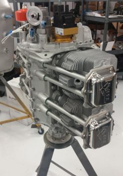
And one more quarter view of the left side of the engine.
•••

