
Chapter 22 – Electrical Components, Tools and Equipment
In addition to the main electrical page that is ordered chronologically, I’ve added a separate web page specifically for Electrical (end) components, tools and equipment. Specifically, end components are electrical devices which would not be classified as Avionics or Instrumentation (battery contactor, voltage regulator, etc.).
In addition, I think electrical system tools and equipment are of interest to most every homebuilder, so I’ve attempted to document all those on this site as well.
3 October 2012 — Tonight I took some pics of some of my electrical components that I received from B&C Specialty Products.
Pictured below is the master battery contactor (silver), the starter contactor (blue), the firewall ground “forest of tabs,” and the B&C LR3C 14v Voltage Regulator. As well as an assortment of FastOn terminals.
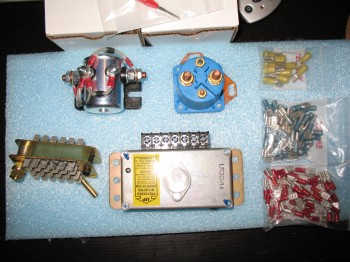
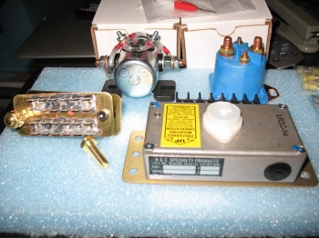
[Operational Note: Currently I am NOT planning on using either of the two contactors shown above]
•••
27 December 2012 — My Christmas present to myself this year was the B&C SD-8 back-up alternator that I’ll be using in Bob Nuckolls’ Z-13/8 electrical system design.
The SD-8 is mounted on the engine’s vacuum pump pad and is used as the primary source of power for the endurance bus in a two-layered electrical system, if the main alternator should fail.
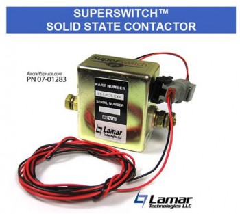
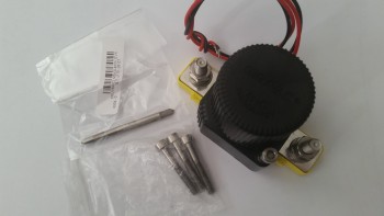
I forgot to add a picture of my (new & improved) Starter Contactor. After a fair amount of research, and talking to some very smart electrical dudes, I’ll be using the Lamar SuperSwitch Solid State Contactor for my starter contactor. From what I understand, these contactors were originally made for the Lancair Columbia aircraft and were apparently made in a decent quantity so that when Cessna bought the Columbia from Lancair, they swapped out the starter contactors and Lamar had a ton left over. So Lamar basically just dumped the remaining contactors for comparatively nothing on Aircraft Spruce. I didn’t take a pic of mine, but this is what it looks like. BTW, I don’t think the P/N in the pic is good any more since I believe ACS sold out their stock of these contactors.
The reason behind moving to solid state is that it has no mechanical moving parts, and is significantly more efficient than traditional starter contactors at a fraction (1/3) of the weight.
•••
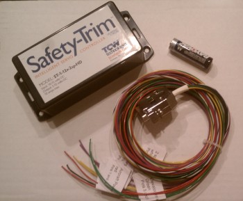
7 January 2013 — I ordered a fairly new-to-the-market 2-speed trim controller from TCW which was made specifically for heavier duty trim actuator motors (read: NOT Ray Allen servos!). Also nicely packaged and looks to be good quality. I had a few long discussions with the TCW bubbas about their different products, and these are some pretty smart guys!
Along with a new Starter Contactor, I also picked up a new Master Battery Contactor: the Gigavac GX-11SA. Why? Well again, in my discussions with the electrical gurus, I realized that to keep as light as possible in my build that I want to utilize B&C’s L40 40 Amp alternator, which is about as light as you can get in alternators (vs the vacuum pad designs). Thus, I need to conserve amperage anywhere and everywhere I can. The standard battery contactor takes about 1 Amp to keep the contactor closed and electrons flowing. The Gigavac GX-11SA has a special internal circuit that once the contactor closes and the circuit is completed, it keeps the contactor closed for less than 1/10 of an amp (0.090 to be exact). So, for the same contactor weight, I gain 0.9 of an amp. Doesn’t seem like much, but when you only have 40 amps to play with, and a decent amount of “electro-whizzies” (as Bob Nuckolls calls them) that you’re using in the cockpit, you want (I want) as much spare power as possible. (The pic below is not my actual Master Battery Contactor, but a representative one… just as I did for my starter contactor).
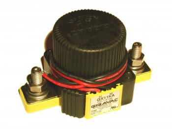
Is there a down side? Yes, there is a slight bit more electrical noise, but according to Bob Nuckolls & Eric Jones, it’s negligible. (The high efficient internal coil is shown at lower right in the diagram below).
•••
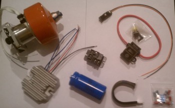
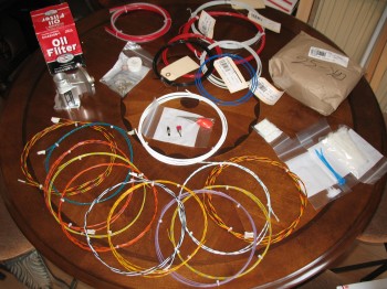
23 April 2013 — I made it back to Germany a few days ago. Below is conglomerate of orders I put in with Stein Aviation for Tefzel wire, switches & electrical stuff (and ACS – 3″ UNI tape for the canard, and B&C – 90° oil filter mount).
•••
21 October 2013 — Well, an alternator is difficult to classify as belonging to ONLY the Electrical System (Chap 22) or the Engine (Chap 23), so I labeled it here as belonging to both categories.
I’ve held off for quite some time in buying my alternator, which is B&C as well, simply because I didn’t feel I had identified the avionics and electrical components within the electrical system to the degree necessary to know what size alternator I would need. B&C offers both a 40 Amp and a 60 Amp externally regulated alternator. Of course an ever-present concern of mine is weight, and at the very aft end of the engine, the 2.4 pound difference (6.1 vs 8.5) between these two alternators clearly has a decent affect on the aircraft’s weight & balance at such a rearward arm. With technology allowing me to have a lighter battery up front (15 pounds vs the traditional ‘old school’ 25 pounds), even with an extended nose I’m trying to keep the hind end of my bird light. Especially considering I’ve dumped an O-320-sized engine back there when the Long-EZ was pretty much (Read: “specifically”) designed for the lighter O-235 engine.
Have I made my case? Quite a bit of yammering over just 2-1/2 pounds, eh?! Sure, weight is evil! (I wonder if Burt would be proud of me right now . . . )
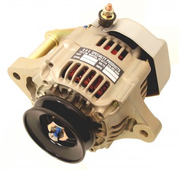
And so it is mis amigos, that I was comfortable enough in my electrical system load analysis at this point in time that I pulled the trigger on the B&C L40 40 Amp alternator below. Also, as a data point, my main bus with all the components I have listed in my electrical system will have a steady current draw somewhere around 22 amps. Not bad for a full up IFR glass panel with autopilot.
As per usual, here is a representative picture from the B&C website.
•••
26 May 2014 — A reoccurring question that I’ve had in my mind for quite some time was simply how to go about labeling all the wires in the Long-EZ to make maintenance, modifications and troubleshooting a heck of a lot easier. Well, recently–most likely due to my recent task of building all the subsystem wiring book diagrams–that internal “reoccurring” question turned more into a “nagging” question.
So the other day I spent a couple of hours perusing my notes, past emails, various builders’ forums and the Internet to find an answer to my now persistent wire-labeling question. After a fair amount of research, and doing a short cost-benefit analysis of the amount of time required to label my wires in one of the few old school methods versus acquiring the capability to do it quickly, I realized that having high quality labeled wires wasn’t going to be necessarily cheap. However, along with high quality labels the one thing I could definitely attain was speed . . . and once you add the ability to produce things a heck of a lot more quickly, with high quality, that simply equates to efficiency in my book. And I am willing to pay for efficiency.
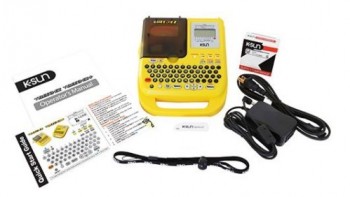
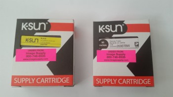
I found a few builders using the K-Sun Bee3-EZ+ label maker (Really?! How can you pass on something that is clearly made for an “EZ”? It even lists it right in the model number! And it’s EZ to use to boot!). Now, I already have a P-Touch label maker that I’ve used for countless years, so why in the world do I need another label maker?! Well, dear friends, this one PRINTS ON SHRINK TUBE! Ok, this may not be news to you, but it definitely was to me. Between the 1/8″ & 3/16″ sized shrink tubes, they cover wire gages from 12-22 AWG. Perfect for covering the vast majority of wires in an airplane build. Moreover, these shrink tubes come in 5 different color combos.
Thus, after reading online reviews, comparing prices, etc., I went back to my old standby eBay and was able to pick up a new K-Sun Bee3-EZ+ shrink tube label maker for over half the cost less of a new one at a regular online vendor:
•••
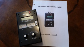
26 February 2015 — In the December 2013 edition of Kitplanes magazine I found yet another useful piece of information, and like so many other times during this build, it came a year or so too late. The article was written by Jim Weir–maker of many canard antennas–and discussed checking the VSWR (Voltage Standing Wave Ratio) of each antenna before burying it under the skin of a plastic airplane such as the Long-EZ, at which point if you have a problem . . . well, better think up some good solutions!
Jim recommended a MFJ-259B Antenna Analyzer to check the VSWR on each antenna to ensure they were good. Again, my antennas already being installed, I still wanted to check them to A) know if any had a VSWR too high to count as good, and B) pick the best between the COM antennas for COM1, and the best between the NAV antennas for NAV1. The goal is a VSWR ratio less than 3:1, because anything higher is a lot electrical energy traveling back along the OUTSIDE of your antenna coax cable to the transmitting device (ie, radio), which will drive your available Tx wattage to unacceptably low levels and could damage your transmitter in the process. In addition, as with so many other units of measurement in the weird & wonderful world of electrons, VSWR readings are logarithmic. Any increases above a 1.5:1-to-2:1 ratio and things start getting real hairy real quick!
I of course started hunting around for a good, used antenna analyzer at an acceptable price anywhere I could find one. That pretty much drove me to eBay, where I picked one up for about half the price of a new one. And thar she be below.
The only problem with my newly won prize (which I actually bought a while ago), was the antenna cable adapter that came with it. These analyzers can be used for checking any antenna and are common in the HAM radio world, so perhaps the antenna cable adapter that came was used for something even more exotic by a HAM radio bubba.
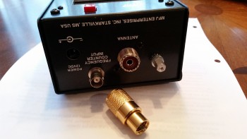 So although I didn’t know what the mystery adapter was used for, I did know that to check the BNC connectors used on the Long-EZ antenna cables that I would need a BNC adapter for the antenna analyzer. So, last week I ordered a couple of them, one male and one female, and I got them in today.
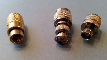
You can see the new BNC antenna cable adapters on the right, and the old one on the left. Below is a shot of one installed on the antenna analyzer.
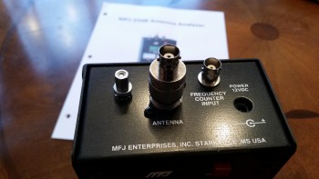
Since the weather is still too cold to economically heat my workshop for glassing, I plan on terminating all my antenna cables with BNC connectors and then checking the VSWR of each one with this MFJ-259B antenna analyzer.
•••
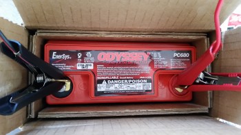
11 November 2015 — Today the UPS guy showed up with the battery charger I ordered from Amazon last week. I ordered this battery charger because in reading the manual for the Odyssey PC680 battery it stated that if the battery charge fell below 12.65 volts, than it needed to be charged before using it. When I checked the battery, the multimeter showed 12.57 volts, clearly below the threshold required to be able to use the battery as per the instructions.
Of course I knew I would need a battery charger eventually since the Odyssey PC680 is an Absorbed Glass Mat (AGM) type that is immune from acid spills and gas venting, and thus has some unique charging requirements to ensure the battery is maintained in an optimized state before it’s actual use in the Long-EZ. An interesting side note to this battery is that it can be mounted in any position.
I checked the Odyssey website for approved battery chargers. After assessing a few battery chargers online, I decided on this one and ordered it.
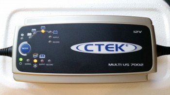
I hooked up the battery to the new charger before heading out to a meeting I had at the office. Before I left for my meeting I went upstairs and changed clothes –about 5 minutes– and when I did a final check before walking out the door the charger had already completed its first 2 phases and was in the basic charging phase. This was a good sign since the initial phases are conditioning cycles that bring a battery back to the point where it can simply be charged in phase 3, where again, my battery was before I even left the house. By the time I returned about 2 hours later, the battery was fully charged and was at 13.87 volts. Not bad!
I’m discussing the battery at this point since the short term use of the battery is to test the nose gear actuator (Chapter 13) while of course the long term use will simply be as the aircraft’s primary power source (Chapter 22).
•••
24 November 2015 — I started out today doing some research on my wiring tools. I realized that I didn’t have a crimping tool for larger diameter wires under 16 AWG, so I did a little research and ordered one online.
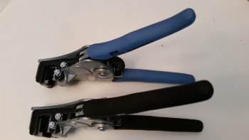
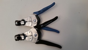
Then, while I was doing an impromptu inventory of my wiring tools, I decided to go ahead and swap out a set of blades to give me a fuller spectrum of MILSPEC wire stripping. The wire strippers to the left in the pic below are mil spec wire strippers that strip 16-26 AWG wires. The wire cutters to the right are basically the same strippers that also strip 16-26 AWG, but with standard wire stripping blades for automative purposes, etc., not for aircraft wiring. While in Qatar I took Nick Ugolini’s advice that he provided on his blog to simply buy a set of aircraft grade mil spec cutting blades (shown to the right below) and install them in a standard, cheaper pair of wire strippers.
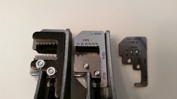
So that’s what I did. But instead of buying 16-26 AWG mil spec cutting blades, I ordered a set of 10-14 AWG cutting blades to give me the capability to strip wires as large as 10 AWG down to 26 AWG wires.
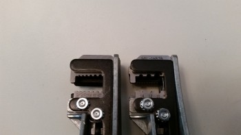
Here’s a couple shots of the wire strippers.
•••
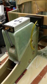
10 December 2015 — Today I mocked up the AEX module and the SkyRadar ADS-B receiver on the NG30 cover.
•••
11 December 2015 — I thought I’d start out today showing a couple things I just received for the build. The first one is the shrink tube for making wire labels.
The other is the titanium metric M5 bolts and an M5 tap for mounting my battery contractor in the nose.
•••
5 February 2016 — I thought I’d add this pic to show you all what the battery strap for securing the main battery in place will look like. This is an initial sample that strapworks.com sent me to finalize the custom strap that I’m having them make for me.

•••
5 September 2016 — Today I started off by logging in the recent Mouser order that I just received. Specifically, I figured out where a couple switches that were in that order actually went. So I labeled a few switches and updated my panel & switch diagram.
•••
6 September 2016 — I today discovered that my UPS friends had delivered yet another Mouser order, so I logged the new parts into my spreadsheet and sorted through the new panel switches. I then identified all the new switches, labeled each one, and stowed them away with all the other switches.
An item of note that I also received today from ACS is the TCW Technologies 3-Amp hour Integrated Backup Battery System (IBBS). After W&B discussions with Marco regarding his new Long-EZ, he had advised me to literally front load as much component weight possible into the nose region of my plane to favorable counter the sensitive rearward balance tendency of Long-EZ’s.
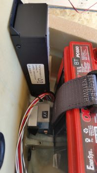
As I mentioned in a previous post, I had originally planned to install a 3AH model IBBS since it would serve me well enough –and for the specific reason that I would be saving weight over the 6AH model. So upon the “load the front heavy” advice I received from Marco, I assessed putting in the bigger model. Ah, but alas, the 6AH model was physically too big to mount it where I had planned (see pic below) so I went with my original plan and pulled the trigger on the 3AH IBBS.
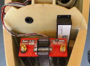
As you can see in these pics, the 3AH IBBS fits perfectly… and according to plan!
•••
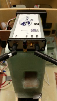
8 September 2016 — Today I asked and got a response on question from the folks at Radenna SkyRadar. I asked a couple of questions on their SkyRadar-DX ADS-B receiver that I’ll be using: First, I wanted to know if I could mount the GPS antenna puck directly on top of the unit (I can!) and, second, I wanted to know if I could get a shorter GPS antenna cable (I can’t). Alexey from Radenna explained that the long GPS cables are pretty standard, and the reason for it is to provide proper attenuation for the LNA which is inside the unit. He also explained that it is possible to find an antenna with a shorter cable, but not in such a small form factor as the one that comes with the SkyRadar-DX. He also provided this helpful link from MGL explaining how to coil up the GPS antenna lead.
•••
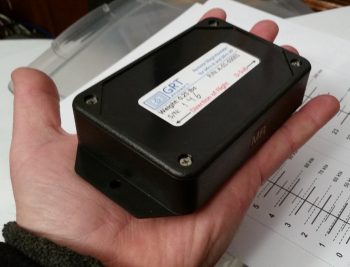
2 April 2017 — In a discussion I had with Marco on some possible avionics upgrades I send him this pic of my GRT Mini-X Magnetometer. Since I had it on hand I thought I would post it.
•••
28 August 2017 — I’ve been kicking around the need for an audio mixer for a while now, but the reality of this requirement hit me as I was helping Marco with his panel upgrade on his flying Long-EZ. If there are more audio inputs coming into the Intercom from such devices that I have on hand like the Trio Autopilot, GNS-480 NAV & system audio outputs, etc. then an audio mixer is required to get all the respective inputs into one signal.
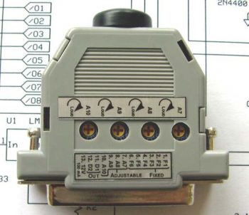
So, I finally made the decision to research out what I needed and make a final decision on what model would fit my requirements. The end result –which I’ve had my eye on for a while– was the VX-Aviation AMX-2A 10-Channel Audio Mixer. Apparently, Vern at VX-Avaition doesn’t sell these any more and has handed over sales control to makerplane.org, which is where the pic below is from.
As you can see, the form factor for this 10-channel audio mixer is a modified 25-pin D-Sub connector so the unit is very small and lightweight. I don’t need it just yet, but it is on my list of stuff to buy so I’ll most likely order one in the next month or few.
In addition, I finalized my decision on the AMX-2A by incorporating it into my Comms wiring diagram.
•••
1 September 2017 — Today I had a whole list of shop build tasks to undertake, but that all went sideways with the myriad of phone calls I had –most plane build related– including working with GRT on finalizing the purchase order on my GRT 8.4 HXr EFIS and EIS4000 engine management system.
Since I had planned on hanging out with an old Air Force buddy of mine tonight, I knew it would be a short build day. So after talking with Jeff at GRT about their optional USB EFIS video input, I decided to explore that capability a bit more before heading out to dinner (i.e. no shop work).
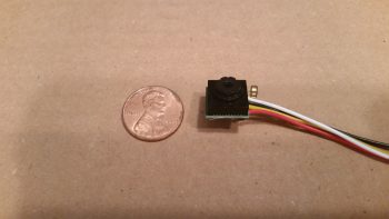
Quite a while ago I bought a very small video camera off Amazon for around $12 to test out. My specific idea was that with all the challenges I’ve heard from Long-EZ flyers about the real world ability of turning their head around and viewing the fuel site gauges in the back seat area, why not exploit GRT’s video input capability by using a couple of mini-video cameras to simply view the site gauge fuel levels (I do have Nick Ugolini’s fuel probes as well that feed the EFIS fuel tank quantities).
For an ounce or two tops in weight I can simply take a quick glance at a video feed in an inset on my EFIS and confirm the fuel site gauge level readings.
In addition, with a camera posted top CL of the pilot headrest looking aft, in one quick glance I can check the status of my top engine cowling and prop. Moreover, I can check the status of the GIB and make sure they’re doing ok.
Finally, since I found a 4-into-1 video feed unit online, I plan on attaching the fourth camera just aft of the front gear T-foot that hangs down in the airstream on the bottom CL of the fuselage. The camera will also be facing rearward to allow me to check on the health of the lower fuselage, landing brake, landing gear, lower cowling and prop. Since the air just aft of the nose gear T-foot will already be a bit turbulent, the mounted video camera’s tiny footprint shouldn’t increase drag by any significant degree.
I figured out the wiring on the camera and dissected it a bit to see how I could use much thinner/lighter 24 AWG aircraft wiring to extend the leads vs using big, bulky, heavier audiovisual RCA jacks & cable leads to connect the cameras up to the avionics bay.
I of course wanted to see how well the video camera worked, so I connected it up to my dining room TV, added power to the tiny camera and Voila! As you can see the picture is definitely good enough to see any details required for my basic needs on the airplane.

With my nascent plan coming together for these incredibly light, tiny cameras, I can incorporate their installation into the build process as I move forward. There of course will be a bit of research and engineering to get exactly what I want as far as the control of what camera shows up on EFIS video feed, but beyond that I’m pretty much set.
Ok, another rabbit trail marked as reconn’ed!
•••
13 September 2017 — Today I had a quick chat with B&C about the mounting requirements for the SD-8 Backup Alternator’s voltage regulator. The new electrical system requirement I picked up from them is that it’s highly recommended that I have a cooling fan for the SD-8 voltage regulator since apparently it runs a little on the warm side.
So, fan on the list to integrate into the GIB headrest. I then integrated this new fan requirement into the electrical system.
•••
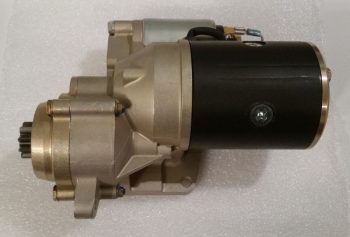
22 January 2018 — Since I hadn’t taken pics of the shy B&C starter and its closest buddy –also shy– the B&C 40 Amp alternator, I thought I’d do so before they get mounted to the engine.
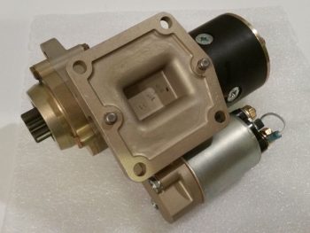 Now, both the Canard Pusher newsletters and B&C touted this starter as “lightweight” and maybe it is compared to other starters out there, but man, when I was dragging this and the alternator down off the shelf in the shop I thought…. that’s a lot of combined weight for the very aft point of the engine, no wonder Burt wanted us to hand prop these birds!
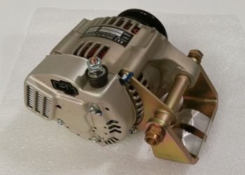
Here’s the shy twin: the B&C 40 Amp alternator. Looks like a quality piece of equipment . . . very robust.
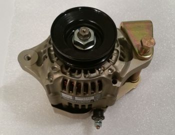 And one final shot of the B&C 40 Amp alternator before it goes back in the box to get mounted on the engine in the next day or two.
•••