
Chapter 24 – GIB Kickplate
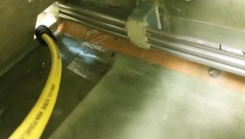
Since I have 3 fuel lines running from the right side of the GIB thigh support front wall bulkhead and the aft side of the pilot’s seat, IN ADDITION to the main aircraft power cables from nose to tail, AND all the other miscellaneous wiring running down the right side of the fuselage, I decided to build and install a kick plate on the lower right side of the GIB area. This page details the build, installation and finishing of the kick plate.
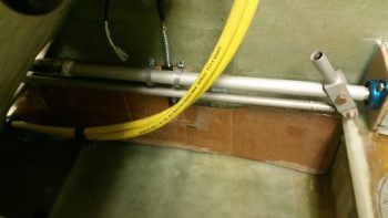
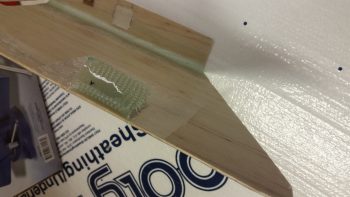
27 July 2017 — Today I tweaked the scrap cardboard template that I started making up last night to determine the dimensions of the GIB right sidewall kick plate. As you can see, it runs from the aft edge of the pilot’s seat to the front edge of the thigh support fuel sump front wall . . . specifically the right side bulkhead.
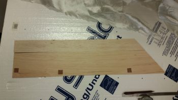
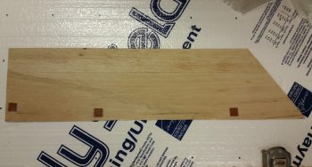
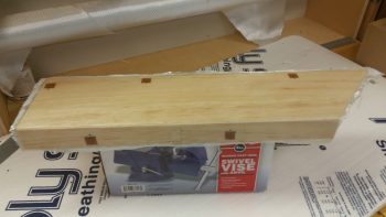
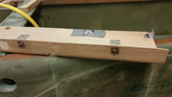
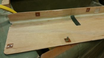
After I got the kick plate dimensions squared away, I then cut up a couple of pieces of 1/16″ thick Balsa wood that I had on hand just for this purpose. I determined where my lower mounting hard points would be, then cut 0.7″ x 0.7″ phenolic pieces and inserted them into the Balsa kick plate to reinforce the areas on the kick plate that will get screwed in place to the sidewall.
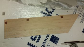
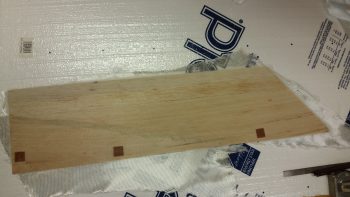
Here’s a shot of the other side, but with all the phenolic hard points and the two strips of Balsa wood micro’d in place.
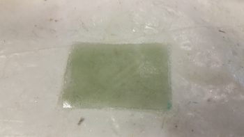
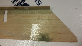
I then laid up 1 ply of scrap UNI on the interior side of the kick plate.
I actually had a lot more planned to knock out today, but late in the afternoon my friends that are moving to North Carolina called and requested my assistance, so I was out most of the evening. I did manage to trim up the layup on the interior kick plate when I returned many hours later.
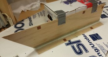
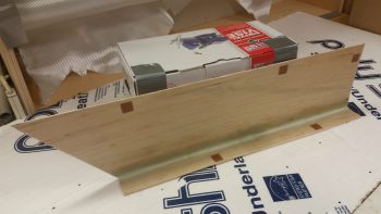
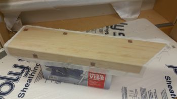
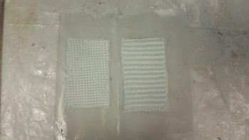
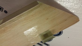
I then cut more Balsa strips for the top, inserted 2 phenolic hard points and prepregged a couple of 1-ply BID layups. I then laid up 1 ply of BID on each end, overlapping in the center. This overlap helps reinforce the center a bit since I used 2 pieces of Balsa for the top, which precluded me from having to use an entire new strip of Balsa wood (remember: I’m cheap!).
I of course used a micro fillet and micro’d the phenolic hard points in place before glassing the interior of the top.
The top is 1.6″ wide, so I used 2.5″ for my width on the first ply of BID to glass both the internal top surface, but also overlap onto the kick plate side piece 0.9″. In addition, I laid up an extra BID tape in the corner that was 1.5″ wide, so it overlapped about 3/4″ onto the top and side pieces of the kick plate.
•••
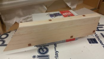
28 July 2017 — This morning I trimmed the cured layup on the underside of the GIB kick plate.
I then cleaned up some areas of dead epoxy that had seeped through to the front side. I then sanded the corner edge down to create a nice, pleasing radius.
•••
29 July 2017 — Today I started off by finalizing the cleaning up & initial round of micro’ing some divots I had made (during cleanup) and the minor gaps between the wood pieces on the GIB right kick plate.

I then let the micro cure a bit as I cut the BID and peel ply for the layup. I then laid up the 1 ply of BID using MGS 335 with fast hardener.
I then peel plied the layup.
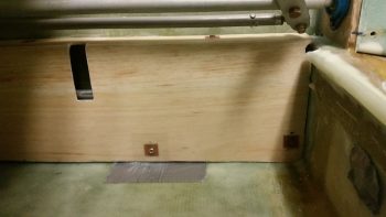
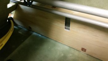
I then took a break, grabbed something to eat and uploaded my pics to this website. A bit later the layup was cured so I razor trimmed it, pulled the peel ply, cut the notch for the roll trim spring assembly, and then test fitted the kick plate in place.
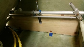
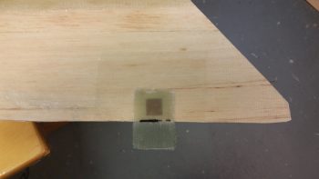
It took a few iterations of trimming both the front and the aft edges of the kick plate to allow it to slide into place, but I eventually got it to settle in quite nicely. Towards the front side top you may notice a square patch where I cut out the interior glass and wood to thin the top out for clearance with the underlying Adel clamp.
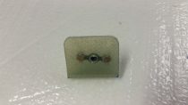
I then made up a brand new 6061 mounting tab for the aft edge and riveted a K1000-8 nutplate to it. I also riveted K1000-8 nutplates to some existing mounting tabs I had made up earlier for the armrests. I then added some protective tape around the mounting holes and mounted the brackets with #8 screws.
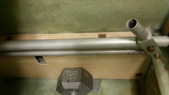
I then whipped up some flox, floxed up the 3 mounting brackets and set the kick plate in place. To ensure the brackets were pressed into place nicely, I rested a weight against the kick plate.
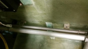
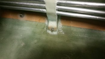
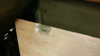
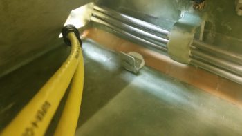
A bit later, after the flox cured, I pulled the kick plate off the installed mounting brackets and cleaned the protective tape off of the kick plate. Here are the 2 upper mounting brackets floxed in place to the fuselage sidewall.
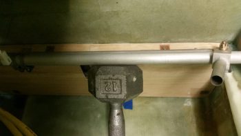
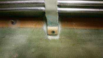
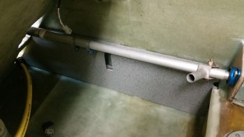
And here’s the kick plate’s aft mounting bracket floxed in place to the front thigh support sump front wall bulkhead.
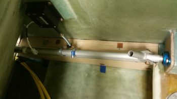
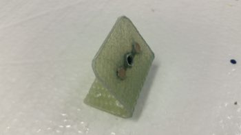
Before I pulled off the kick plate I drilled an 11/64″ hole through the bottom aft phenolic hardpoint in the kick plate. I then widened it out in the fuel line bracket to accept a RivNut hardpoint that I’ll use for this mounting point.
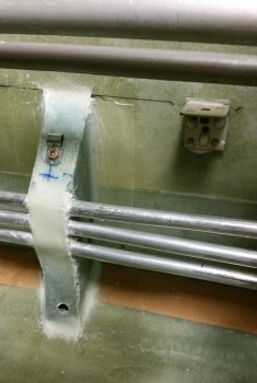
I cut a few grooves into the RivNut to add some gripping power and taped up the end with duct tape.
What’s not seen here (you’ll see it when I remove the kick plate) is the 1/4″ thick Divinycell foam spacer that I floxed into place between the kick plate interior side and the fuel line mounting bracket. The inboard half of the RivNut is floxed into the foam spacer while the rest of it is floxed into the fuel line mounting bracket. The spacer itself is floxed on the outboard side to the face of the fuel line mounting bracket.
Later, after the RivNut & foam spacer flox cures, I’ll layup 1 ply of BID around the spacer to secure it and the RivNut to the fuel line mounting bracket.
I then used the same 12-pound weight pressed against the lower RivNut hardpoint (and foam spacer) to keep it securely in place.
After I finished writing the majority of this blog post, I went back down to the shop to catch the flox on the lower kick plate RivNut hardpoint in its “green” stage of curing –where it’s still just a little pliable– and I was able to do so [Incredibly easier when the epoxy/flox/micro is in this stage… it has the consistency of caramel candy and can be cut and removed without much difficulty]. I removed the screws and pulled the kick plate off its mounting tabs, and then cleaned up the flox that had oozed out from around the sides of the 1/4″ Divinycell spacer. Here’s the (nice & clean) result:
•••
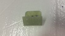
9 August 2017 — Today I set my sights on finalizing the GIB right side kick plate mounting. I started by stuffing some plastic saran wrap into the aft lower hardpoint screw hole, and then laid up a ply of BID over it.
A few hours later it was really close to being cured, so I hand drilled the hole through the glass in the front to remove the plastic. I then cleaned up around the hard point screw hole and test fitted the screw.
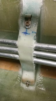
Here’s another wider angle shot of above.
I then prepped both the outboard side fuselage area and of the interior wall of the kick plate with clear packing tape to keep the composite bracket from gumming anything up.
I then set up 2 prepregged 3-ply BID layups.
I then wet out the prepregs and combined the 2 stacks of 3 plies to make up a 6-ply forward kick plate mounting bracket.
I then laid up the 6-ply bracket layup half way onto the forward kick plate mounting hardpoint.
I then folded it back on itself so that it was almost touching. My goal here was that when the kick plate was mounted, gravity would simply pull the glass down onto the protective tape on the floor, creating the exact correctly shaped bracket blank –since the floor at the corner here is 45°– after it cures.
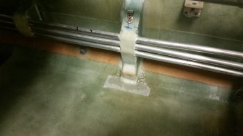
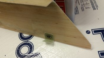
Here’s a shot of the entire kick plate, with the 6-ply mounting bracket glass formed on the inside. I was able to get just a peak of it through the holes in the front seat bulkhead and from what I could ascertain, my “shot in the dark” layup looks ok.
•••
10 August 2017 — Today I started out by pulling the GIB kick plate out to check the forward mounting bracket layup.
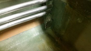
The mounting bracket looked good with the angle appropriate to how the lower corner of the cockpit is shaped.
I could tell by the bottom of the cured mounting bracket that not all of it was in contact with the taped fuselage corner . . . I guess gravity isn’t what it used to be!
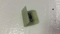
I first drilled the #8 screw mounting hole through the kick plate and part way through the forward lower bracket when it decided to remove itself from the kick plate. I then drilled and riveted a K1000-8 nutplate to the mounting bracket, and then trimmed all 4 bracket sides with the Fein saw. Finally, I drilled anchor holes and sanded the bottom of the mount that will get floxed to the fuselage corner.
Here’s a few pics of the completed forward kick plate mounting bracket.
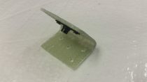
I then remounted the composite forward mounting bracket onto the kick plate.
Knowing that only a small portion of the mounting bracket had been in contact with the cockpit corner when I set it, I slathered it up with flox before remounting the kick plate. I used fast hardener… so a few hours later after it cured I pulled off the kick plate to find that my mounting bracket floxing endeavor was successful.
Later, I primed & painted the kick plate with my gray cabin granite paint. Over 4 hours later I hit it with a couple coats of matt clear coat.
This is about an hour later after the clear coat was dry enough to set the kick plate in place to get this pic.
Here’s another shot of the painted and clear coated GIB kick plate. BTW, I checked the weight of the kick plate just prior to painting it and it weighed in at a whopping 5.8 ounces.

•••