
Chapter 25 – Cockpit/Cabin Paint
This page covers the painting of the majority of the cockpit, cabin and seats prior to the strake build to allow for easier reach into the cabin while painting.
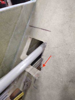
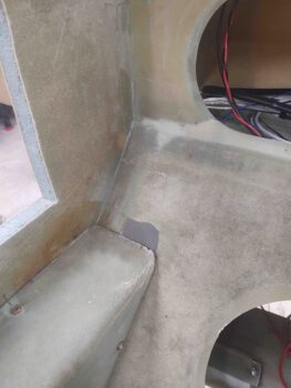
20 November 2020 — Today I started some seat back hole filling along the edges of the armrests, both on the front seat (red arrow).
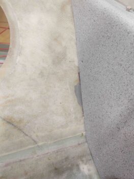
The upper right GIB seat . . .
And the lower left GIB seat.
I also filled the back side of the through-seat hole edge on the back of the pilot seat, as well as installed a clickbond to secure the landing brake cable with an adel clamp.
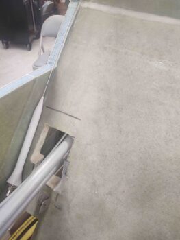
A couple hours later I pulled the peel ply and cleaned up the interior cockpit cleanup layups. Here’s the shots of all those:
•••
21 November 2020 — Today was pretty much all about electrical stuff, in prep to try to get the interior cockpit painted while the weather is good.
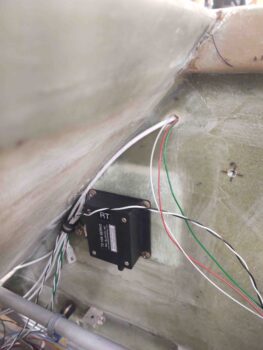
I started off creating a 16″ x 16″ plus sign out of copper foil tape for the ELT back plane. I started with one 16″ long strip of coper foil tape, and then added two 8″ pieces to it with a small gap in between them. I then simply added solder to all the edges and I got me an ELT backplane.
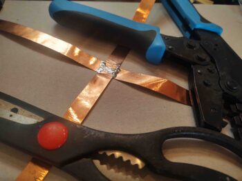
I then soldered the high-grip washer that came on the ELT antenna to a wire, and then soldered the wire to the copper foil strips. This will give me the required electrical continuity between the antenna mount and the backplane, as per the ACK E-04 manual.
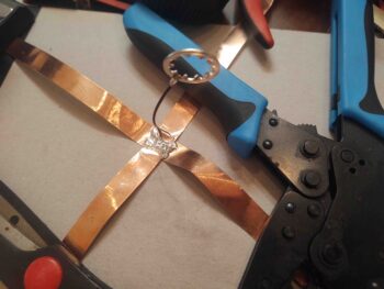
I then installed the ELT copper foil backplane into the right corner of the pilot seat. If you think the right angles for the backplane are incorrect, well, then you’d be incorrect… hehe. According to the owner and lead bubba at ACK, right angles like this are perfectly acceptable for a backplane. The big concern is actually having a backplane in a composite aircraft!
I then covered all the copper foil legs of the ELT backplane with a ply of BID. A fair bit of which I peel plied.
Jumping ahead a few hours, here’s the cured overlaid BID on the legs of ELT antenna backplane . . . yes, with MGS epoxy it’s hard to tell that there’s anything there.
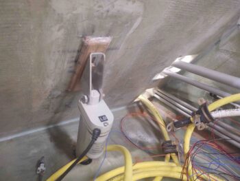
During the copper foil tape protective BID layup I added a couple plies of BID just below the crosspoint of the 4 backplane legs, and when it cured I floxed in the ELT antenna mounting bracket (in pic above too). Here it is a few hours later after the flox cured, with the antenna in place for a test fit. I think this dawg will hunt….

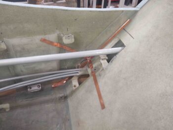
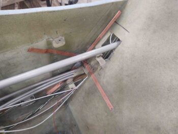
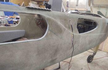
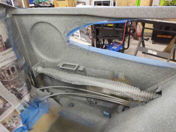
One of the many things I’ve pondered over the past few years was exactly how to run the GNS-480 GPS antenna cable from the panel mounted GPS to the pilot headrest-mounted GPS puck.
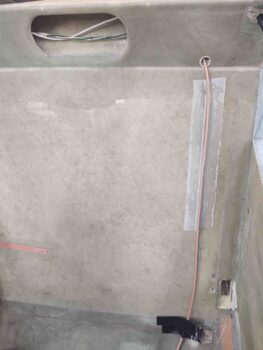
Here’s a shot of the GNS-480 GPS antenna cable when the pilot’s headrest is opened to access storage.
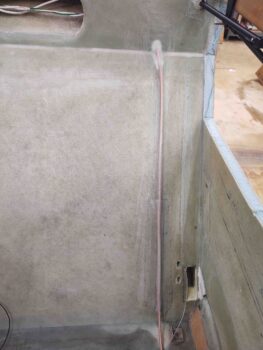
I finally decided that instead of punching through the back of the pilot’s seat at a low(er) point just to have the cable re-enter again towards the top, I would run the GPS antenna cable up the front face of the pilot seat bulkhead. I have it positioned so that it is right at the edge of the seat cushion. just barely covered by it.
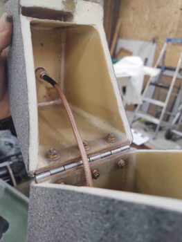
I don’t like making things inaccessible in case they need maintenance or repair, but I figured this cable is fairly low on the failure scale, so I simply glassed it to the front face of the pilot’s seat with a ply of BID. This is the first of a few piece of BID that will secure the GPS antenna cable to the front seat back.
I then got to work selecting some 16 AWG wire and building a cable for the GIB cigarette lighter style charger. I also printed off some labels and labeled the wires and the cable.
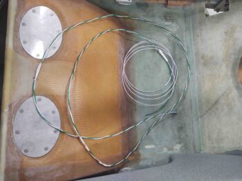
I then did the same thing with some 20 AWG wire for the GIB USB charger unit.
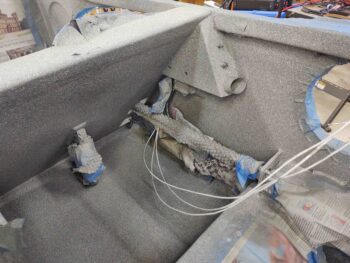
I then ran the wires from the USB and cigarette lighter chargers from the left GIB sub-panel over to the right side and out a hole I drilled in the pilot’s seat back just forward of the roll trim actuator pad.
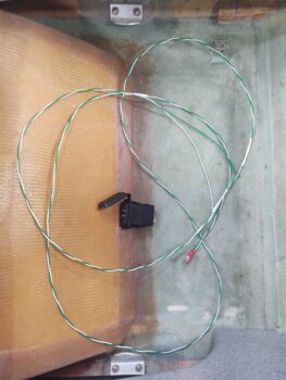
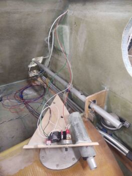
I then grabbed the GIB right sub-panel and ran 2 sets of wires: The first went out the side wall to power/control the GIB map light. The second was the GIB lights power and ground wires that go forward to the TriParagon.
Also note that I 5-min glued the relay to the interior side of the right GIB sub-panel. I then had a small strip of 1-ply BID left over from the ELT antenna backplane layup, so I used it to help secure the relay to the inside surface of the sub-panel, just behind the switches.
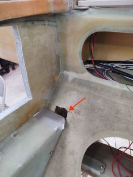
In addition to the the chargers on the left GIB sub-panel, I also routed the cables for the fuel site gages video cameras. The left side cable transits through the pilot seat back, while the right side comes straight in through the side wall.
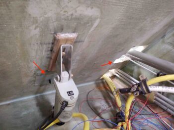
BTW, I just today glassed in the clickbond that the adel clamp is mounted to.
Here’s the left side fuel site gage video camera cable. This cable also includes the power leads for the fuel site gage LED.

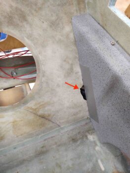
Here’s the wires exiting the fuselage on the right side into what will be the interior wall of the strake baggage compartment. These wires are for the right fuel site gage video camera, the power wires for the fuel site gage LED, and the wires for the GIB map light.
•••
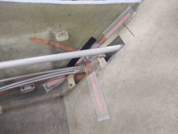
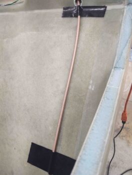
22 November 2020 — I got to work on pulling peel ply and cleaning up the final layups on the GNS-480 GPS antenna cable. Apparently I forgot to grab pics or report on my GPS antenna cable progress, but here it is in its final state before the cockpit gets painted.
Again, with MGS epoxy it’s hard to tell, but there’s a ply of BID securing the GPS antenna cable from the bottom of the pilot seat back bulkhead to the top where the cable enters the seat back structure/rollover base.
•••
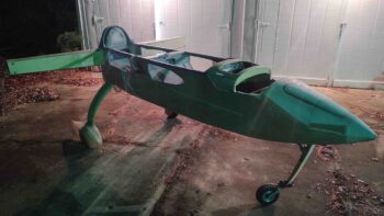
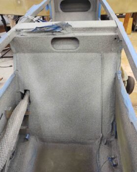
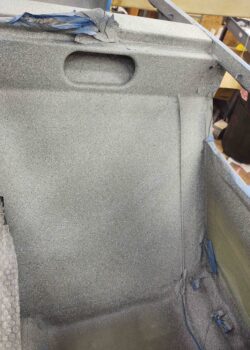
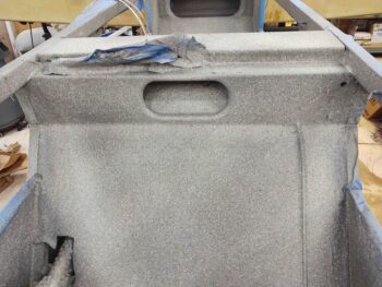
23 November 2020 — With no rain and a high of 67º forecasted, I then got to work sanding, prepping and taping off the cockpit for paint. I missed my target time by a few hours, but I was still able to get this guy out the door, apply a couple of medium coats of primer followed by a couple coats of Rustoleum gray stone paint (just like the canopy and armrests).
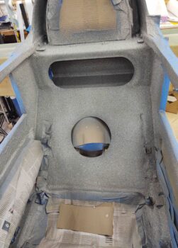
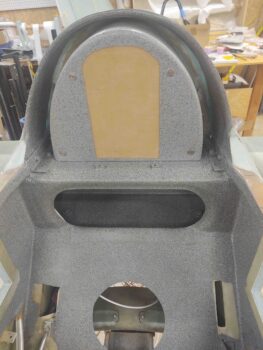
The rest of this post is simply a smattering of shots of the painted interior cockpit. Here we have the front seat area.
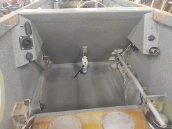
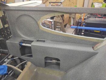
And the GIB area, including the newly mounted side sub-panels.
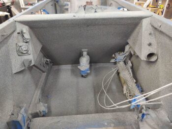
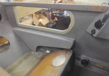
And the pilot seat sidewalls.
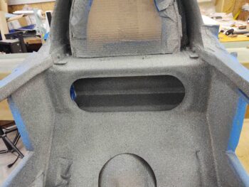
And the back seat.
•••
24 November 2020 — The weather temperature high today was only 58º, but I call that good enough for clear coating, although I waited until mid-afternoon for the weather temp high to be reached at which point I pulled the fuselage back out of the shop and proceeded to clear coat the cockpit paint I shot yesterday.
This stuff is dry –but not usable– within a good 20 minutes, so I carefully but expeditiously removed the blue painters tape.
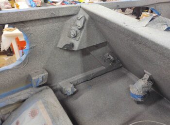
This gives you an idea of what the cockpit will look like when finished.
Moreover, this area here, the back of the pilot’s seat and the GIB floor, is the primary reason I wanted to paint the cockpit at this stage. As challenging as it was to paint with no strakes and access-providing sidewall openings, I can’t imagine painting all this with strakes on!
Here’s looking aft at the back seat and D-Deck. You might note that the area around the GIB headrest is not painted. I taped that off since I’ll be mounting the fuel tank vent lines back against the front face of the firewall that will then loop up, over and around the headrest to vent on the opposite side of the D-Deck vs the tank side (i.e. left side vents for right tank).
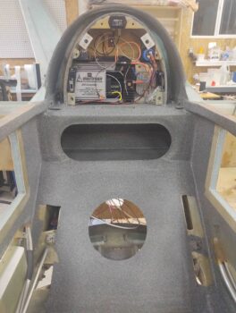
To check out more of the cockpit paint, I then re-mounted the GIB headrest/D-Deck cover plate.
I then rounded up the front seat right armrest and set it in place as well… I’m loving this paint!
Finally, I set the GIB left armrest in place. I’m finding little areas that will need paint, tweaking, etc. when I do cockpit paint round 2 after the strakes are installed.
You may note some slight color variations of the armrests, GIB headrest plate, etc. with the freshly painted cockpit. IMO this paint is a lot like Candy coat paint: it’s a bit finicky and the final color, depth and shade solely depends on how many coats you apply.
Starting out I was more concerned about paint weight, so I did a coat or two less than I just did on the cockpit. Lacking the OCD affliction that so many home builders have, and I know I’m weird, but I like the story that the slightly different shades of components tell. We’re building hand-carved airplanes here, so a little variance is a good story in my book!
•••