Mid-March to Mid-April 2011 — Now that I have my shop set up I need to make some specialized building tools & equipment. Most of the following equipment is listed in Chapter 3 of the Long-EZ build plans with directions on how to construct them.
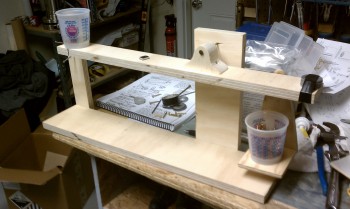
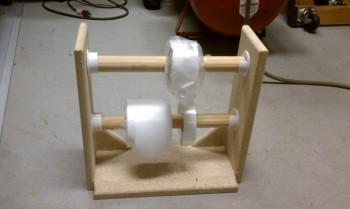
I built my first tool, the epoxy balance, some what out of curiosity & nostalgia to get a feel for how so many builders built their entire Rutan canards in the early days. It’s simplicity is just shear brilliance, which is of course what is said about so many things that Burt Rutan dreamed up.
How the balance works is that after it’s calibrated weight-wise for a given epoxy system, epoxy resin is poured into the big cup & then placed on the lower balance swing arm (shown in the lower right of the picture below). Then, a small paper dixie cup is placed centered on the line (where the upper plastic cup is shown) on the left side of the upper arm. Then, the builder simply adds hardener until a nail on the front side of the swing arm (barely seen) drops down and lines up with a line that is drawn when the balance is set in a balanced/neutral state. For MGS 335 that ratio would be pretested with 38 nails in the upper cup to the left, to 100 nails in the lower cup on the lower right.
The balance works great for small to medium-sized layups, but later on I had to set history aside and go with the much quicker and simple electronic scale to establish my epoxy-to-hardener ratio.
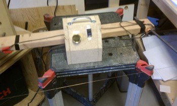
My next specialized tool—that’s not normally found in a DIY’ers garage—is the hot-wire foam cutter. The directions for building the hot-wire cutter is also spelled out in Chapter 3. I built it using a scrap 2×4 and just a few items bought from my local home improvement store: 1/2″ metal tubing and a long length of lamp cord with a plug. But there is one actual specialized part of this cutter: the wire. Normal wire is too weak and not heat-resistent enough to keep from stretching or breaking when the current (aka heat) is applied to the it. So, I ordered some Inconel hotwire from Aircraft Spruce.
To be honest, after playing around with this a little bit, I never used the hot-wire cutter much. After I ordered my foam wing cores from Feather Lite I didn’t have plans on using it much at all.
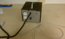
The electrical control for the hot-wire cutter is simply made up of a transformer, a switch, an electrical plug, and a wall dimmer switch. I built a housing for it made of particle board with some vent holes to keep the heat down.
For my unending use of micro & flox, and eventually some Cab-o-sil, I got some nice quality kitchen (flour/sugar) bins with tight-clasping lids. If you look on the bench you’ll see a huge number of paper cups and a bunch of tools (a lot of Harbor Freight!) that our EAA composites instructor recommended [use the plans method of reusing the resin cups and you’ll save a lot of cups and a lot money… thank goodness my buddy Marco reminded me of this early on!]
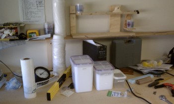
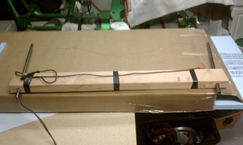
Below is just a small stand I made out of particle board to hold one of the most exasperating things known to man: peel ply tape (due to all the myriad of strings that bunch up on the sides of it). The three sizes that I buy from Aircraft Spruce are shown: 1″, 2″ and 3″.
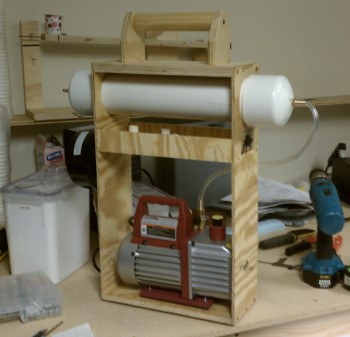
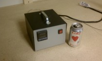
The next two items on my list of items to build are definitely NOT listed in the Long-EZ build plans. The PID Controller (shown in the row below) and the Vacuum Pump Assembly (bottom pic) are somewhat more esoteric tools, if you will, and not nearly as widely used in the standard composite homebuilder’s toolkit.
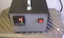
The PID (proportional-integral-derivative controller) Controller is really a thermostat on steroids. It’s main feature is that it variably controls temperature over a period of time. This comes in handy in post-curing composite structures & components, which makes them much stronger and heat resistant. I used them somewhat to begin with (I like to learn and try out stuff that may make things much easier), but learned that trying to post-cure after each piece is built is not the most efficient way of building a Long-EZ.
Using a vacuum pump (correctly!) in laying up fiberglass components greatly helps in sucking out excess epoxy (epoxy = weigh & excess weight = bad). If done properly, which isn’t difficult, vacuum bagging parts creates significantly lighter and stronger components.
The PVC tube at the top of the setup (below) simply helps smooth out the air so that no pulses or irregularities pop up during the vacuum bagging process. The vacuum pump I used was one I picked up at Harbor Freight, and it created good vacuum bagged parts. Unfortunately, the downside was that it produced a lot of smoke and misted oil when used for long periods of time. These negative aspects finally overrode the positive aspects of vacuum bagging and I set it set aside as I started getting into the larger pieces (especially after the debacle at the end of Chapter 6 in Virginia!).