
Elevator Rebuild
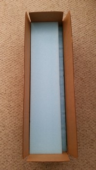
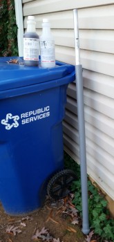
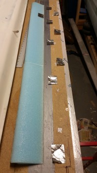
5 November 2015 — As you can see by the pic below my new elevator cores arrived from Eureka CNC! Thanks Steve!
•••
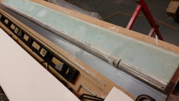
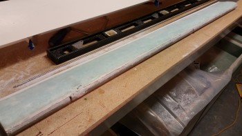
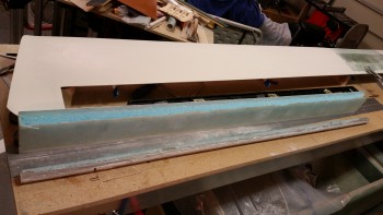
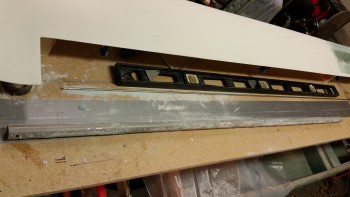
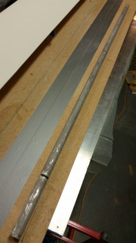
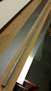
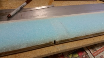
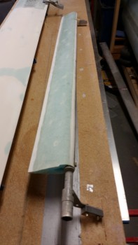
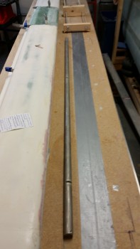
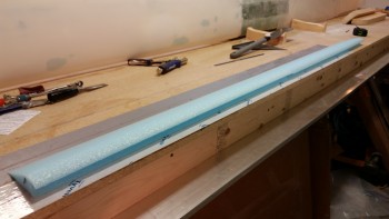
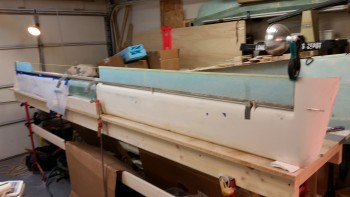
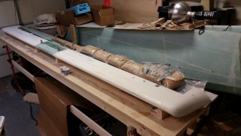
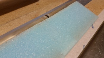
9 November 2015 — My first step was to ensure the table surface was level for the elevator build. I pulled out the über awesome aluminum straight board that I picked up in Germany to check the work bench alignment. From the corner to about 60″ in I had just about 30 thou of sag in the table. A couple of quick shims and everything looked good, straight and level.
I laid down some duct tape where the TE of the elevator will run on the table and then got to work deconstructing the elevator.
The first task was to remove the torque tube offset from the inboard side.
And then the elevator weight on the outboard side.
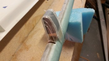
After cutting the UNI plies at the base of the foam on top & bottom, I gave the weight a sharp rap, snapping it off. Unfortunately it came off a little less gracefully (read: intact) than I had hoped for, but I think with some judicious application of flox it may very well work on the next elevator. BTW, as you can see below, the UNI pretty much peeled right off the weight with a little effort, but not a lot.
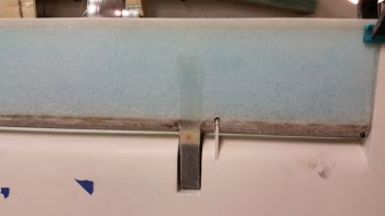
I then broke out my old friends, the NC-7s, to get a gauge of how they line up currently in the hinge tab slots.
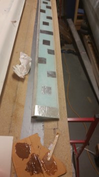
I diced up a popsicle stick to make spacers for the current NC-7 gaps to replicate this on the next elevator when the core is mounted to the tube. And yes, I’m allowing for the .020″ that comes into play for the skin thickness.
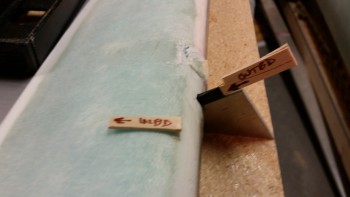
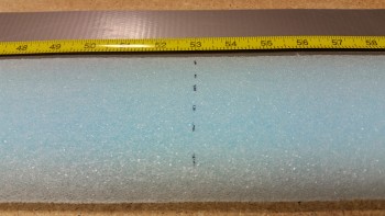
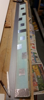
I set the current elevator in a good position for the next one as it gets constructed, and then made some alignment marks in a number of places to help ensure the elevator core gets mounted to the tube in the same configuration as the current one.
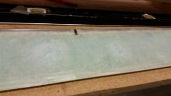
This pic may be a tad fuzzy, but here is the underside of the elevator with its significant thin areas due to intense sanding over the delams that are root cause of all the issues I’ve had with this elevator. Not good.
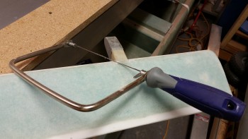
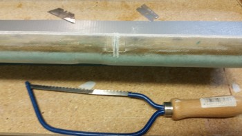
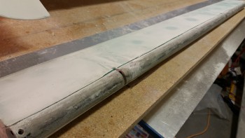
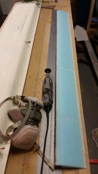
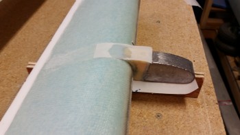
I broke out the Fein saw and started cutting right at the junction of the elevator core and the elevator tube at a very shallow angle.
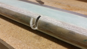
I would track this cut for a bit until the blade broke through the fiberglass, then was able to move forward another few inches before having to come back to the surface and start the process again. Here is the actual cut through the skin.
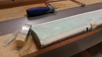
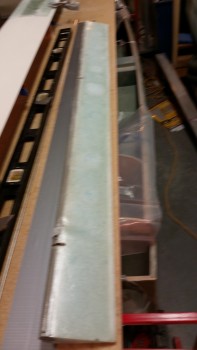
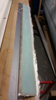
And here’s the entire bottom side of the elevator skin cut just aft of the tube.
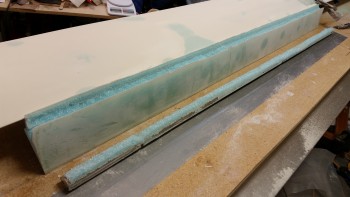
I then moved to the topside and did essentially the same thing.
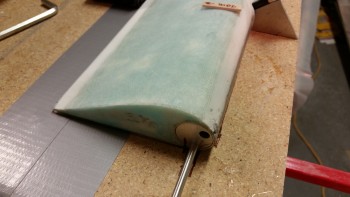
I had to put a metal rod into the top of the elevator tube to pry it gently from the foam core, but it came off with a good amount of pressure.
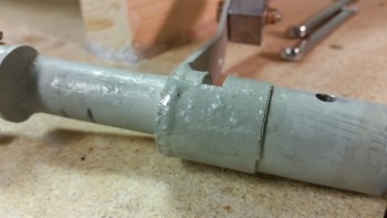
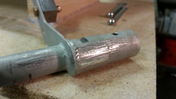
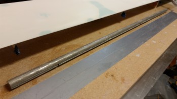
Here’s the elevator tube after I went to town on it with the Fein saw to knock off all the leftover foam, epoxy & glass residue. I then filled up a PVC tube with white Vinegar and dunked the elevator tube into it about 3/4’s of the way up the tube (not shown). I’ll let that sit overnight and see if it softens up the goobers on the elevator tube.
•••
10 November 2015 — Today I took the elevator tube out of the PVC tube filled with white vinegar and flipped it over to get the untouched 25% into the vinegar. I cleaned off the majority of gunk with paper towels, then grabbed my razor knife and started cleaning off the dead glass. I got as far down as the second hinge hardpoint (NC2).
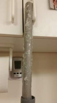
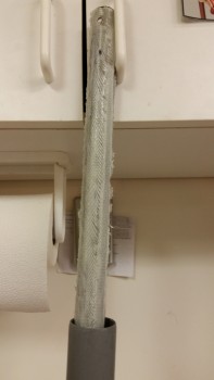
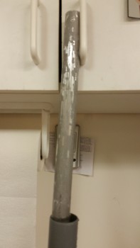
After getting as much of the soaked dead glass off the tube as possible, I set the elevator tube back into the PVC tube filled with vinegar to soak.
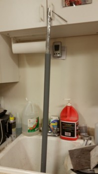
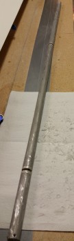
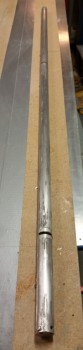
Here’s a couple shots of the elevator tube in its current state. I would say it’s about 90% clean, and after I shot these pics I put it back in the PVC tube to soak in the vinegar over night.
Next I plan on doing a final clean of the elevator tube, sanding down the surface, and then Alodining it in prep of micro’ing the elevator core to it.
•••
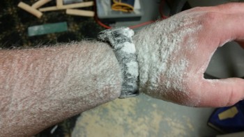
11 November 2015 — I pulled the elevator tube out of the vinegar-filled PVC pipe and did a final clean on the tube. I then washed down the elevator tube with Simple Green before taking it outside to Alodine it.
I washed out the PVC pipe, filled it full of Alumaprep, and then submerged all but about 18″ of the elevator tube into the Alumaprep. Since my Alodine chemicals are weak, I left the tube in the Alumaprep for about 8 minutes before taking it out, rinsing it with water and giving it a good scrub. I then put it back into the Alumaprep with the other end in first.
After the Alumaprep wash, I rinsed down the tube and did the same process in PVC pipe #2 filled with Alodine. Again, I left it in there way longer than normal, about 8 minutes per side since the Alodine was weak. After the time had passed, I again gave the whole tube a good rinse with clean water.
I hung the freshly Alodined elevator tube up to dry and then began to prep for micro’ing the elevator foam core to the tube.
Now, I was seconds away from taking a picture of the Alodined elevator tube when my long lost buddy Greg showed up. Unfortunately when I loaded up all my pics at the end of the evening I realized I hadn’t taken the picture, which is unfortunate because I thought the Alodined tube turned out rather well.
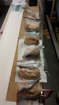
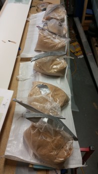
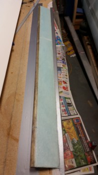
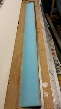
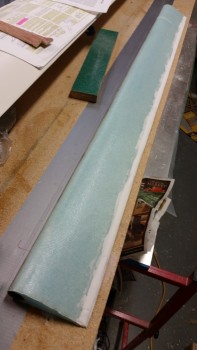
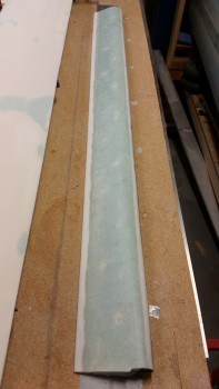
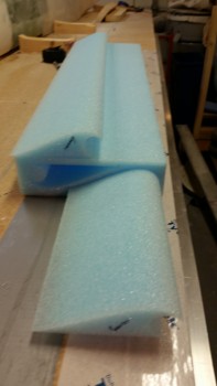
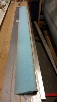
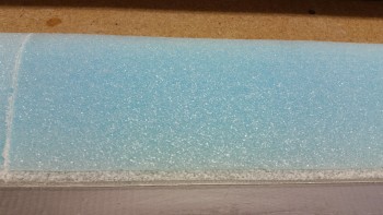
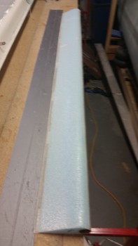
As for the foam cores, since I ordered only the elevator cores from Steve at Eureka CNC, he could only send me the cores cut in half for shipping purposes. The pics below are shots of one elevator core cut in half.
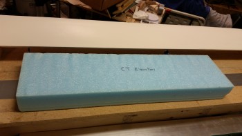
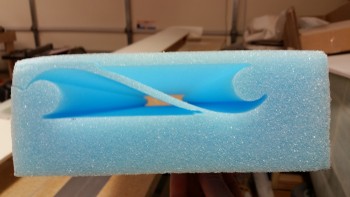
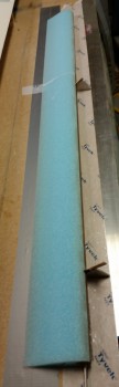
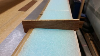
Here are the two halves end to end.
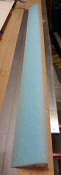
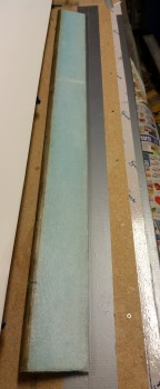
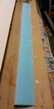
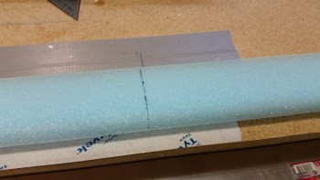
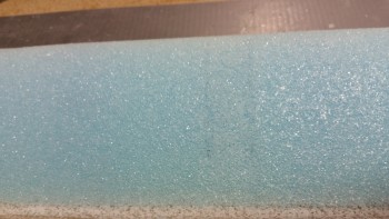
I marked the second elevator foam core piece to cut to length, making the total combined length of these elevator foam core pieces 53″ to match the length of the elevator tube.
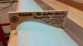
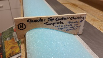
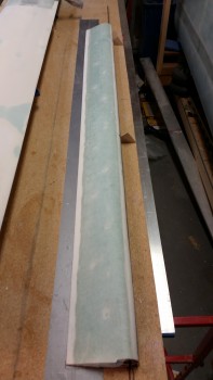
I then did a quick check of the top elevator contour with template “H” and it looked good.
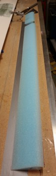
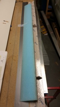
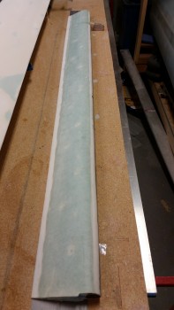
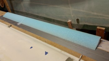
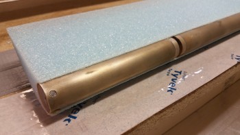
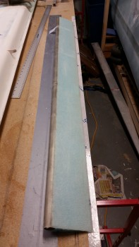
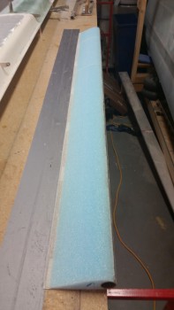
Here’s a pic with the elevator core pieces cut to the proper 53″ length. [Note: these are the correct length of MY elevator cores for this airplane, since I widened the fuselage at all the bulkheads, my F22 & F28 are just a hair wider than the stock plans dimensions. This widened fuselage resulted in slightly shorter elevators.]
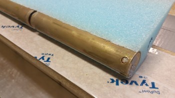
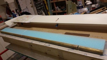
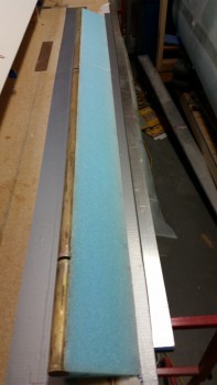
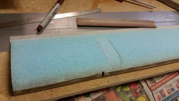
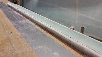
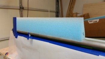
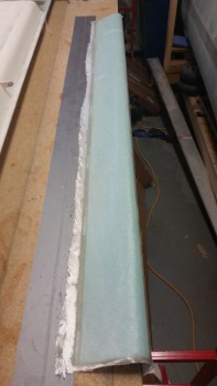
And here’s the two elevator core pieces micro’d to the elevator tube. Yes, the elevator reconstruction is under way!
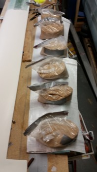
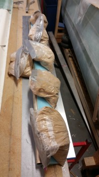
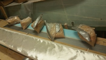
As per plans I weighed down the elevator core & tube with sandbags to keep them firmly in place.
Tomorrow I plan to glass the bottom skin, and possibly the top skin, of the elevator.
•••
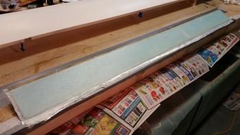
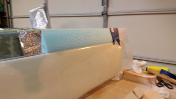
12 November 2015 — Today I focused entirely on the elevator. Below is the elevator core micro’d to elevator tube.
I prepped the tube by taping up the holes in the hinge pin hard points (NC2s) and the elevator tube end insert (NC6).
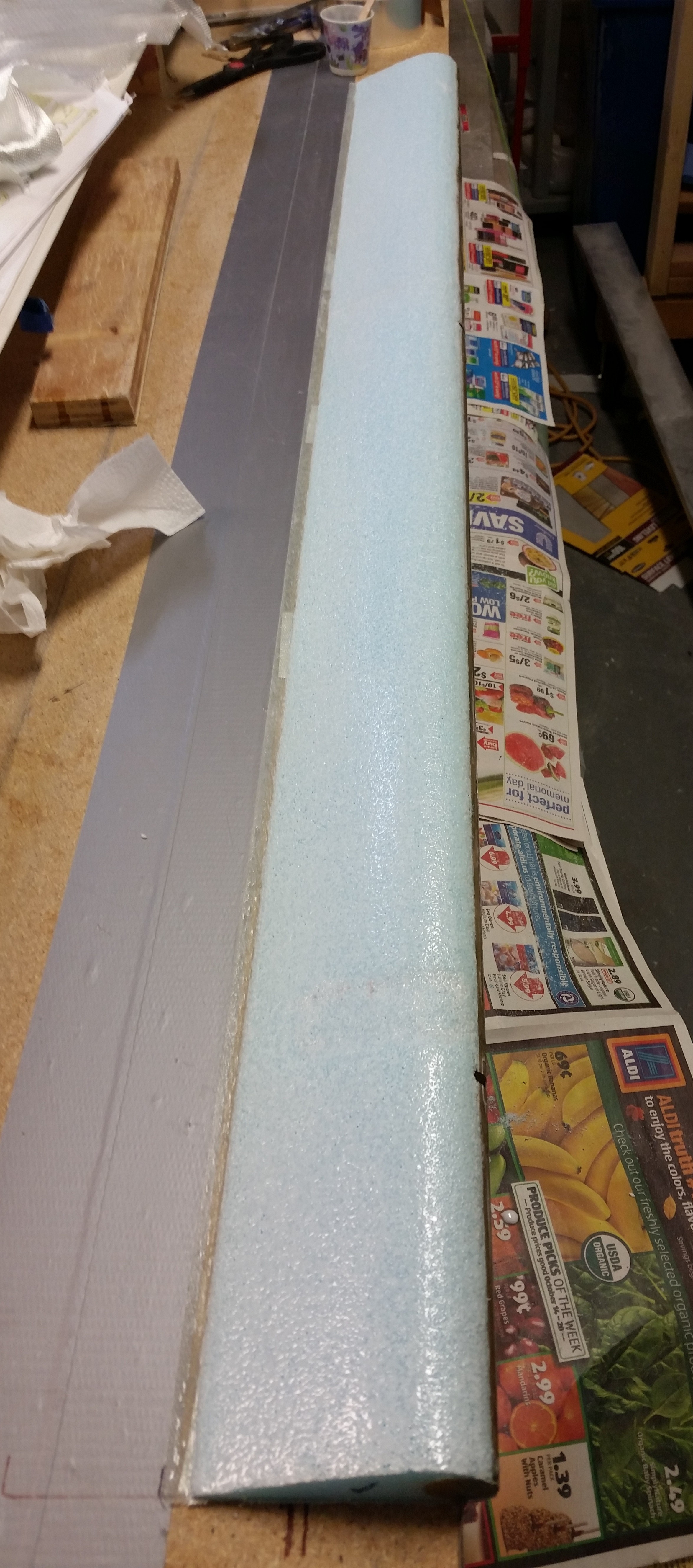
Before glassing the bottom skin I lightly sanded the bottom front edge of the foam core where it intersects with the elevator tube. I also cleaned up the micro at the seam between the two elevator foam core pieces.
To minimize any damage to the foam surface, and thus minimize backfills to the foam, delams and in turn weight, I applied foil tape to the surface of the elevator top. I figured I would try this method instead of applying 5 minute glue directly to the foam.
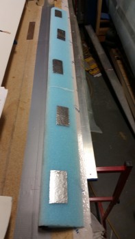
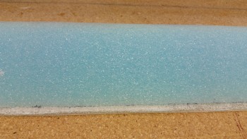
I then quickly checked the bottom contour of the elevator.
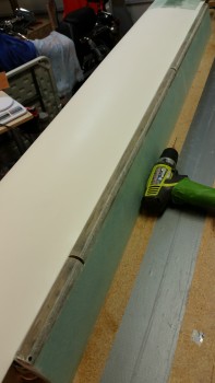
And then mixed up some 5 minute glue, applied a good sized drop to each piece of foil tape, and attached the inverted elevator core to the work bench. I weighed down the TE with sandbags.
After the 5-minute glue cured, I did final check on the foam before I glassed it.
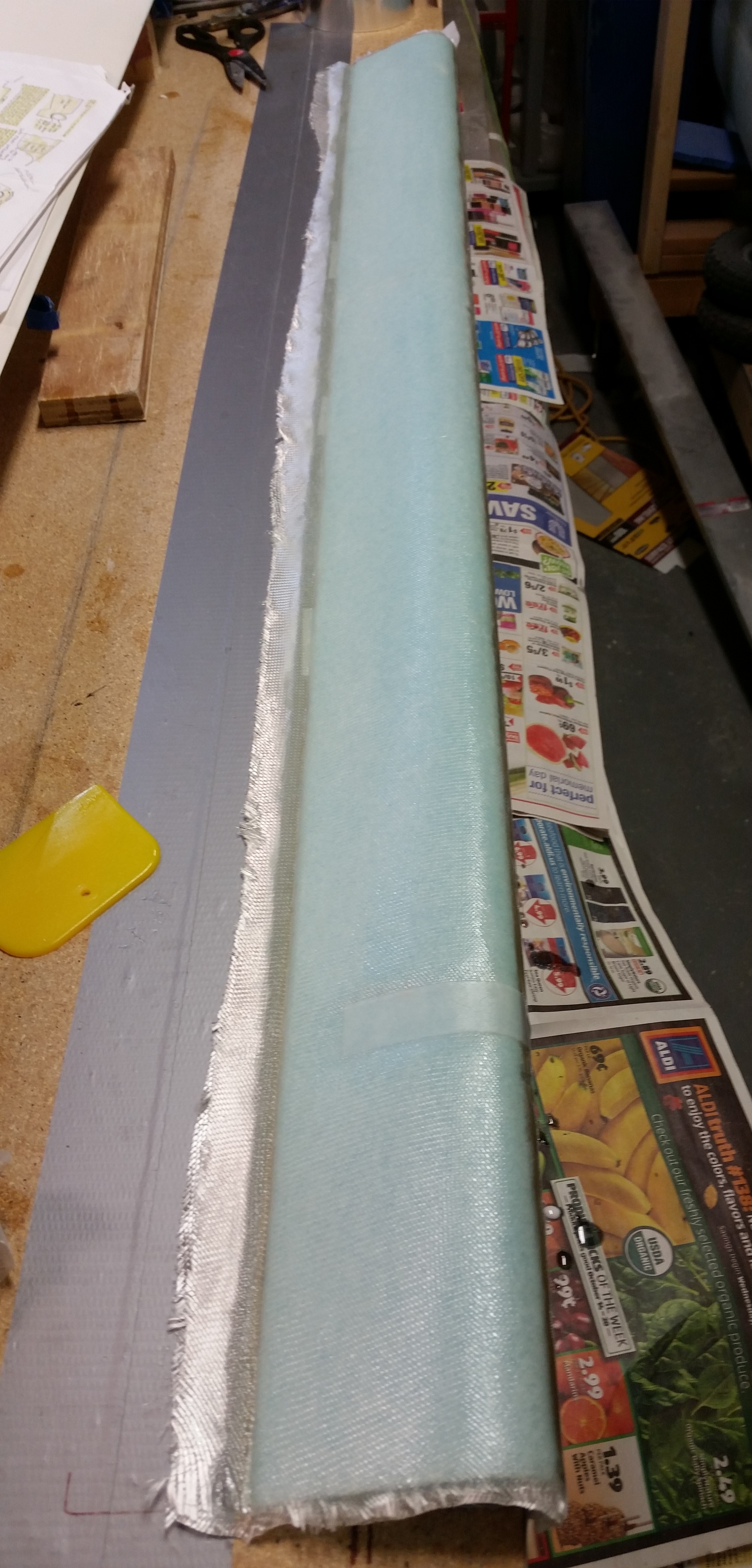
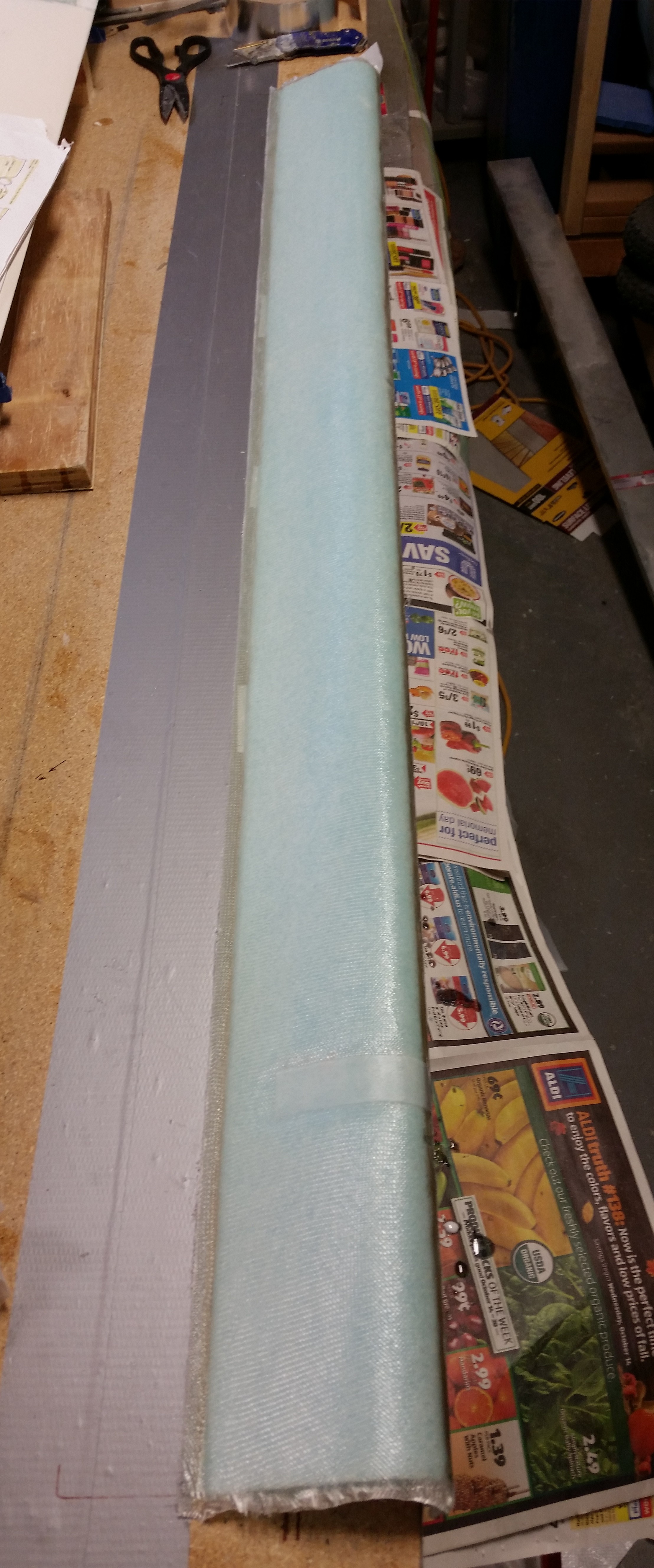
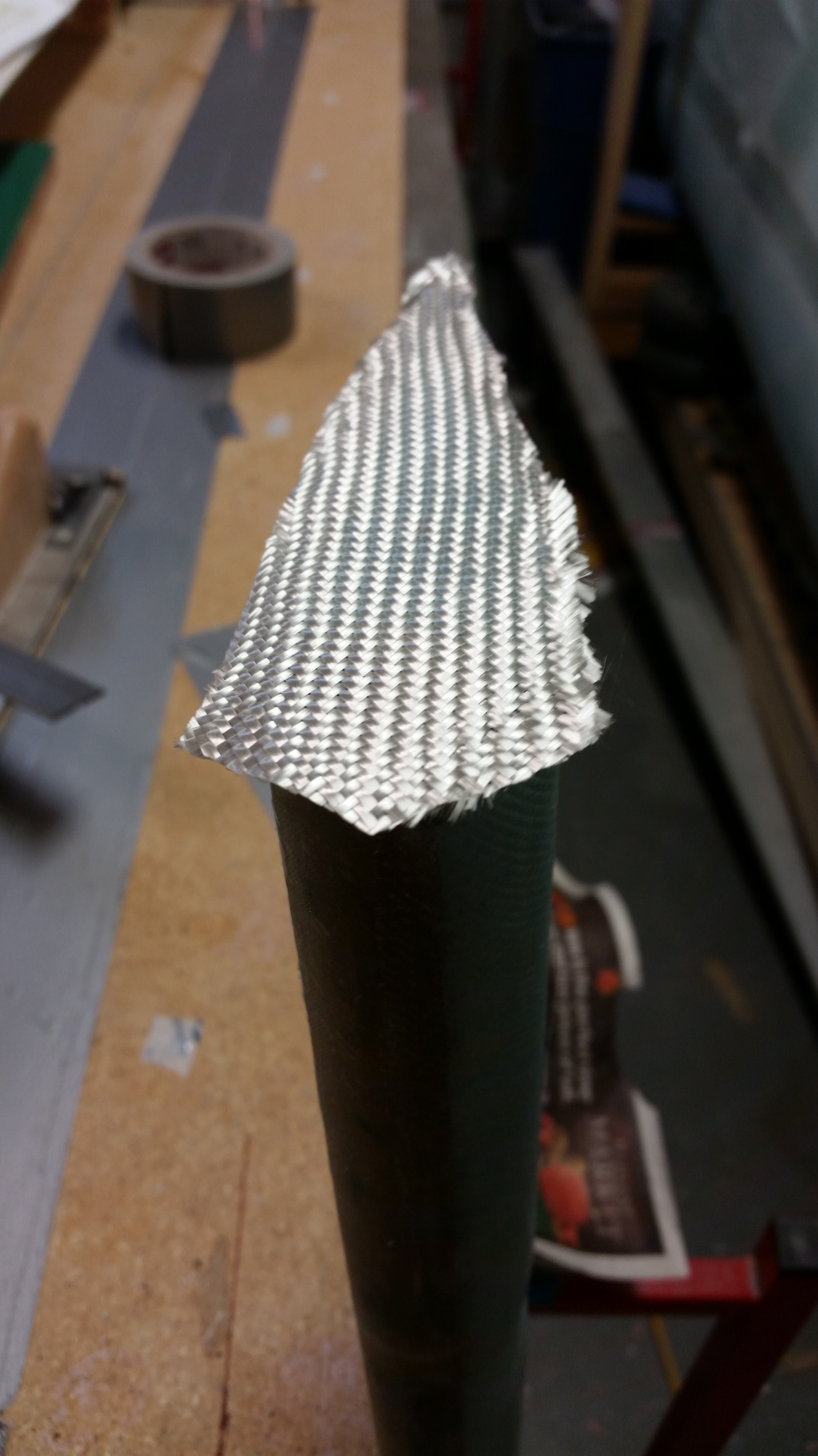
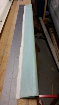
I also checked the UNI glass to ensure it fit. I then glassed the lower elevator skin 2-ply UNI layup using fast hardener.
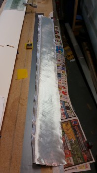
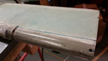
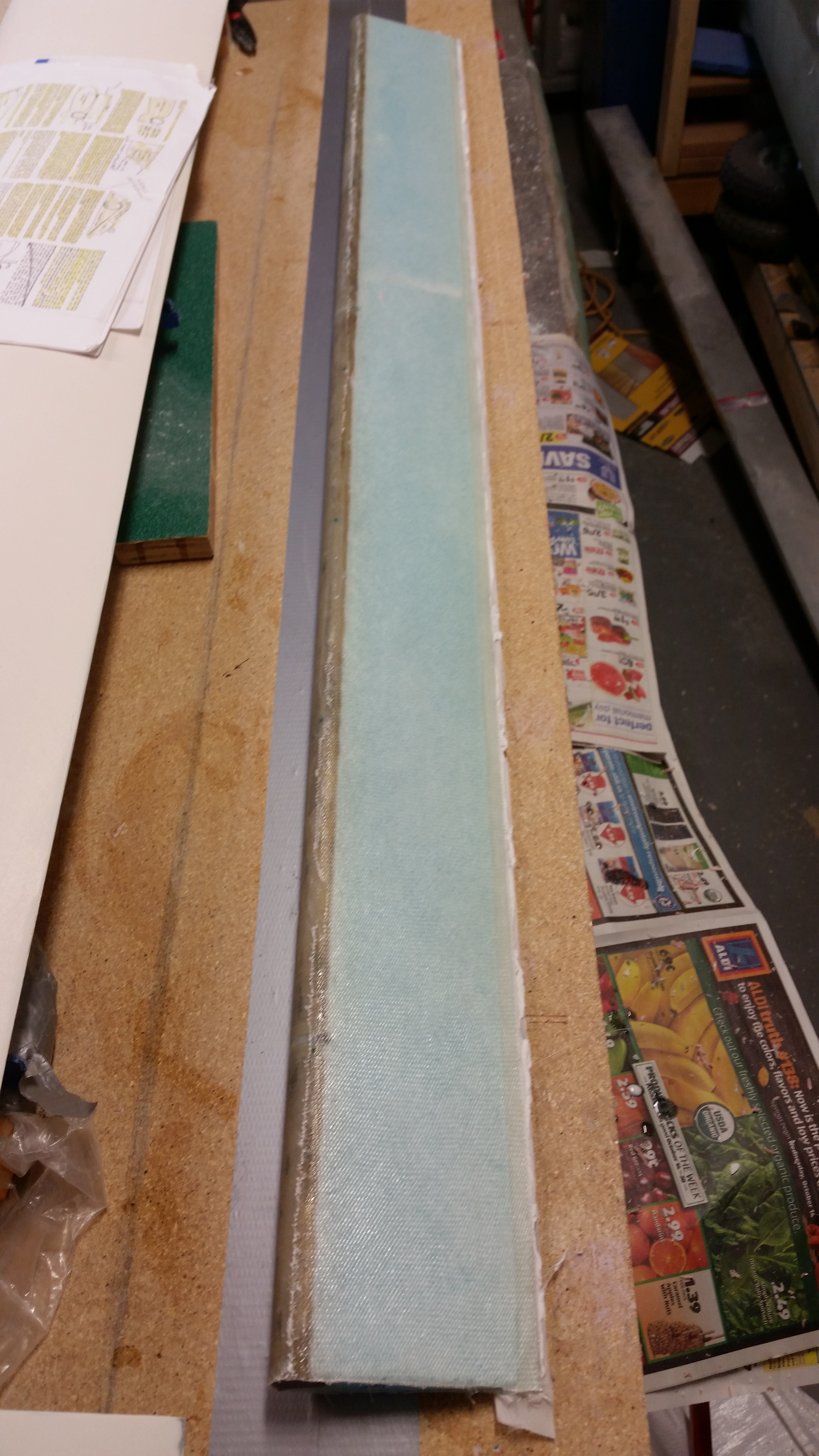
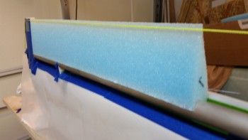
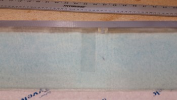
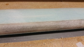
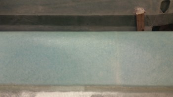
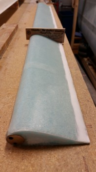
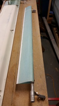
Here’s the (new) glassed bottom of the elevator.
Here are some shots of the finished elevator bottom, in various stages of razor trimmed glass.
I was going to glass the top skin of the elevator as well, but I went out to dinner tonight and it took forever to get our food, so I just didn’t make it back in time to fire up the Dremel tool to trim the TE in order to get good glass-to-glass contact between top & bottom skins.
Next I’ll prep the elevator & glass the top, and then glass the outboard elevator end glassed.
•••
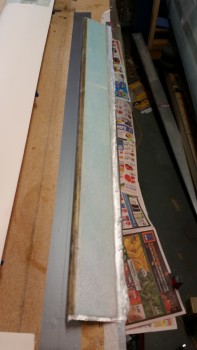
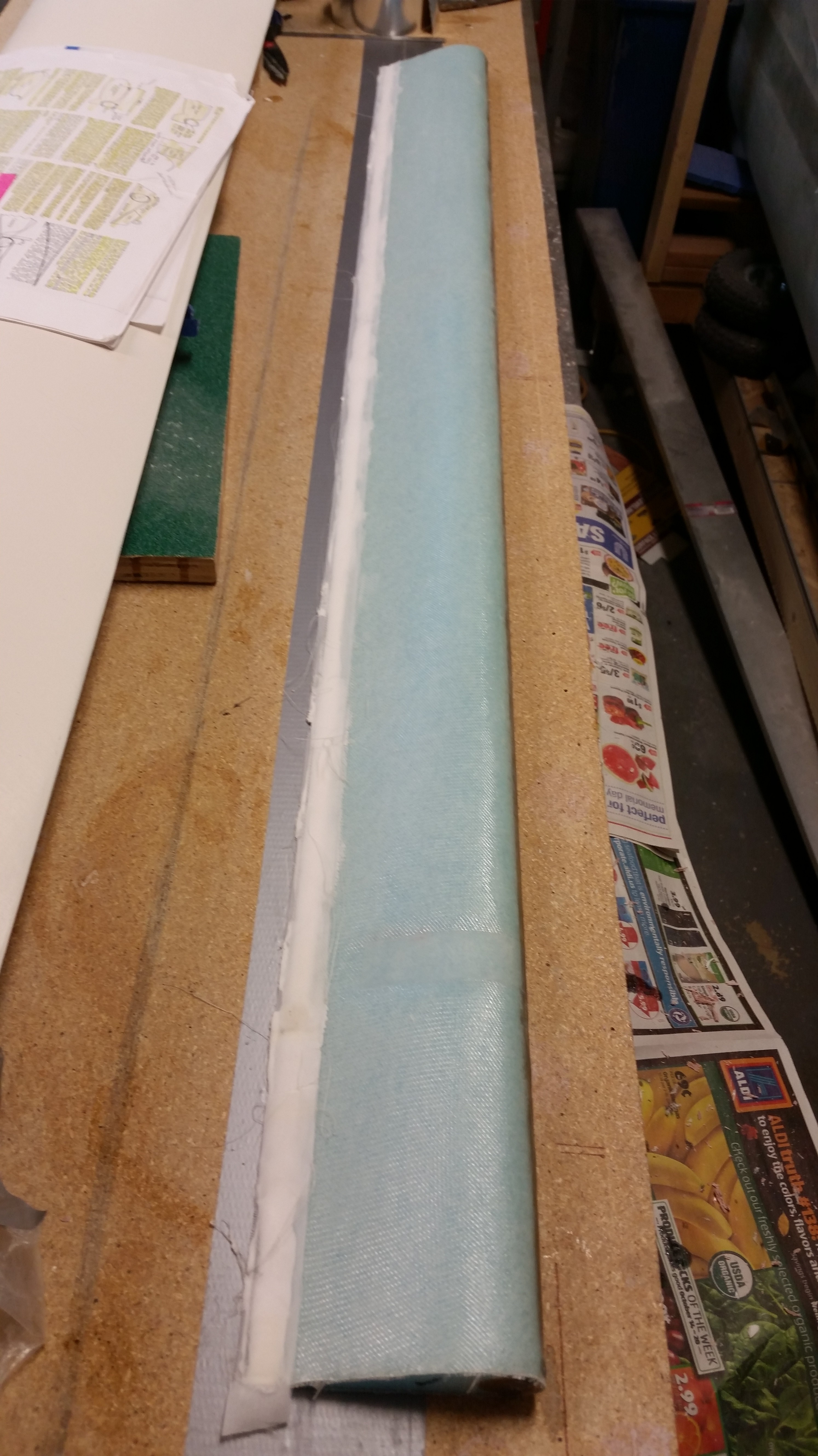
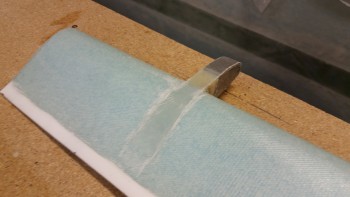
13 November 2015 — Here’s a shot of the trimmed elevator as it looked when I started working on it today.
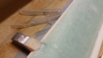
I pulled the elevator off the workbench and was happy that by using the foil tape I had NO divots on the top of my elevator foam. In addition, you’ll note the blobs of 5 minute glue on the table.
For whatever reason the 5-minute glue blobs came off rather easily. After about 5 minutes with a chisel and a razor glade the table was clean.
I then sanded the TE even. After sanding I marked a line about 0.32″ forward of the TE for the glass-to-glass continuity between top & bottom elevator skins.
After removing the foam with my razor knife, i sanded down the TE glass with a sanding board.
I then Dremeled the remaining crud off the TE to finalize the prep. And here’s the results: ha!
I again did a quick check of the top contour with the “H” template.
Although I forgot to do this on the bottom (Doh!) I did remember to add the depression in the foam for the UNI plies that attach the outboard elevator weight.
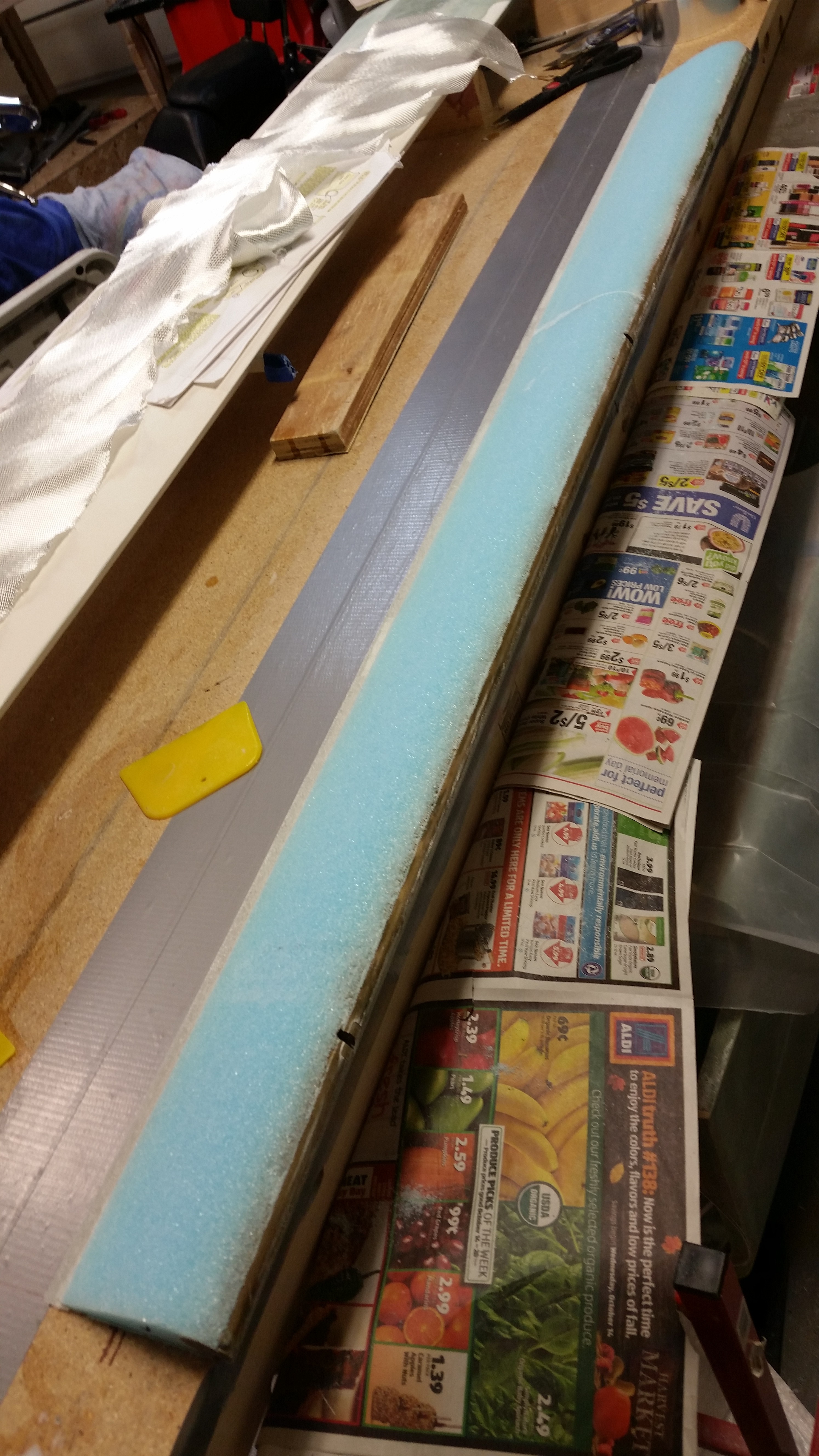
After I finished all the prep actions for the layup, I flipped the elevator over and applied foil tape to the underside of the elevator. Again, I’m doing this to avoid all the issues I had with the previous elevator, and exactly the reason why I’m rebuilding this elevator!
After applying SMALL Bondo blobs to the foil tape pieces I mounted the elevator to the table and then weighed it down with sandbags.
I went back downstairs and vacuumed the foam before starting the layup.
I then micro’d the top elevator surface.
And laid up 2 plies of UNI at 30° in opposite directions.
Since I used fast hardener I only had to wait about an hour before the layup was cured to a green stage. I then razor trimmed the TE.
And then applied dry micro on the TE and covered it with peel ply.

I turned on a heat lamp to help get this thing cured as fast as possible.
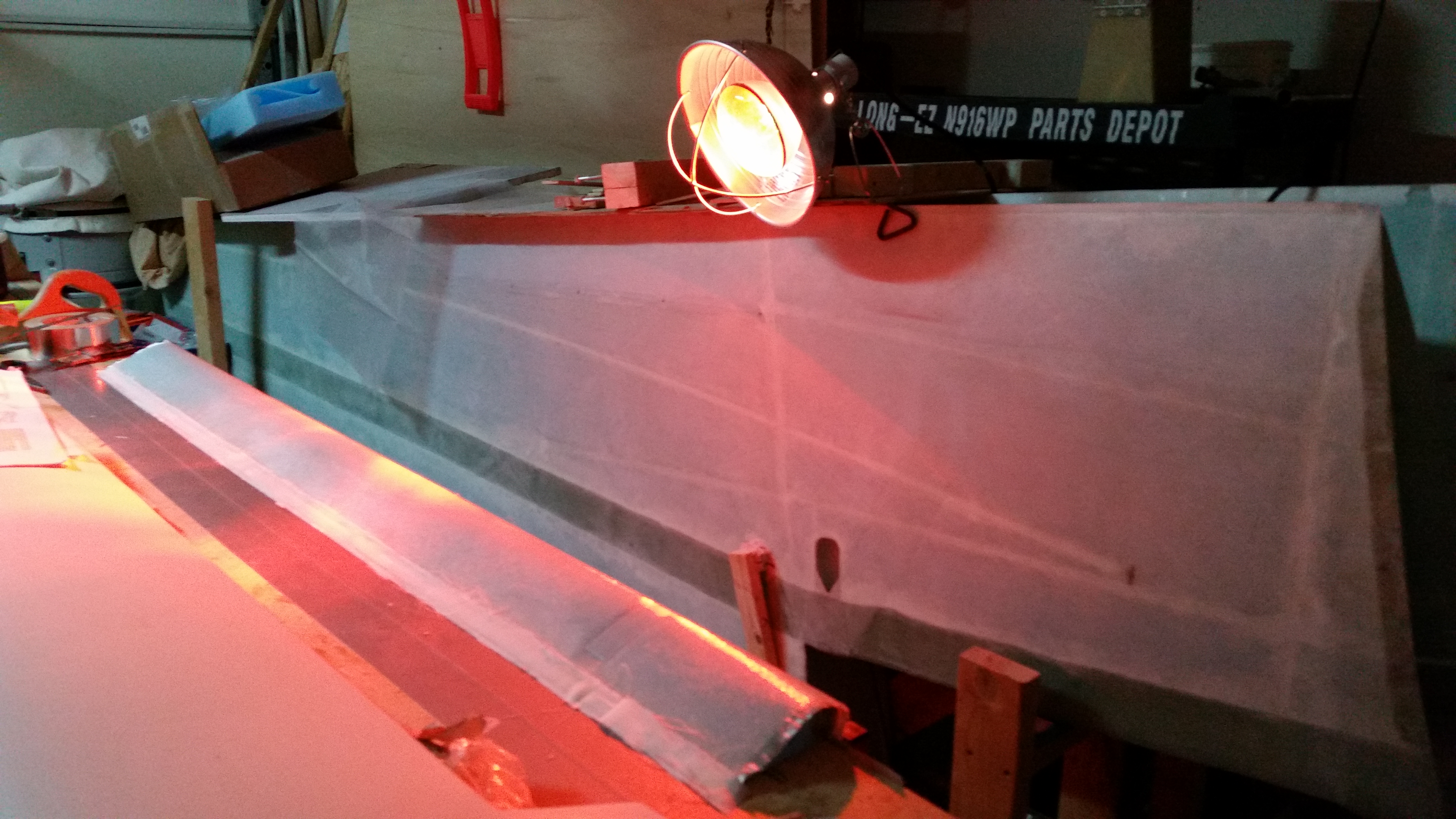
After watching some TV and working on this post for well over an hour, I then went down to the shop to check the elevator top skin layup. It all looked good and was pretty much cured. I carefully pulled the elevator away from the table mainly to keep the TE micro from securing the elevator permanently to the workbench and causing real mayhem if I had waited until tomorrow to pull it off the bench.
After pulling the foil tape off the elevator bottom I was ecstatic that the elevator bottom was SO clean & devoid of that Bondo crap that caused all the issues with the previous elevator! I couldn’t help but think how EZ this would have been had I known this trick back when I first built my elevators!
My next order of business was to cut away any stray LE glass overlap to keep any of the barbs-from-hell, that may have slipped past the peel ply, at bay. I also cleaned the blobs of Bondo off the table. Which thankfully came off fairly easily.

After cleaning up the LE, I then pulled the peel ply from the outboard weight depression.
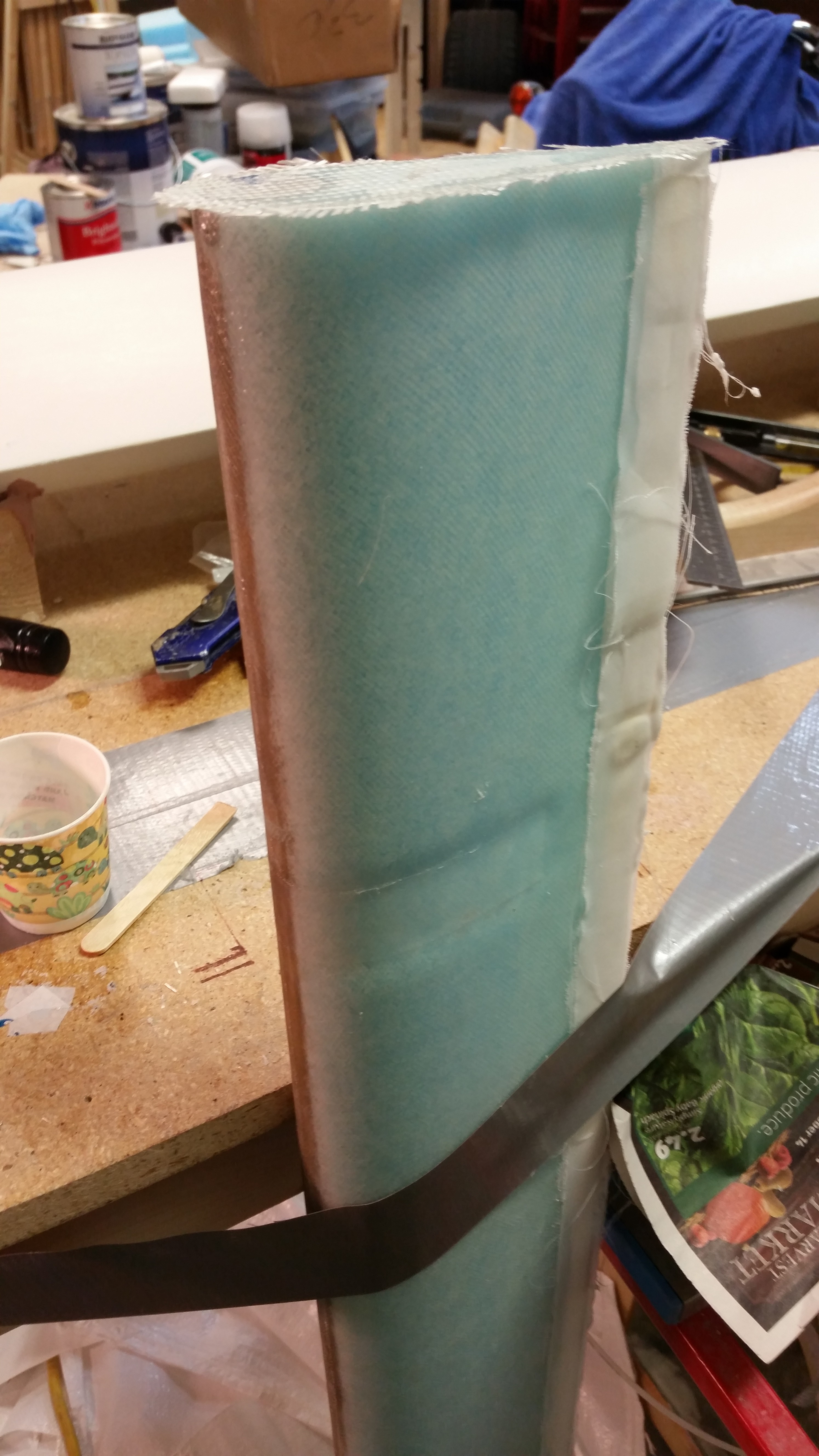
I then checked the contour again, only this time obviously with the top skin glassed. Looking good!

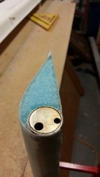
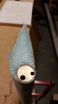
I then focused on the outboard elevator in order to prep that area for the 1-ply BID layup that it will receive. I sanded the glass edges square and even with NC-6.
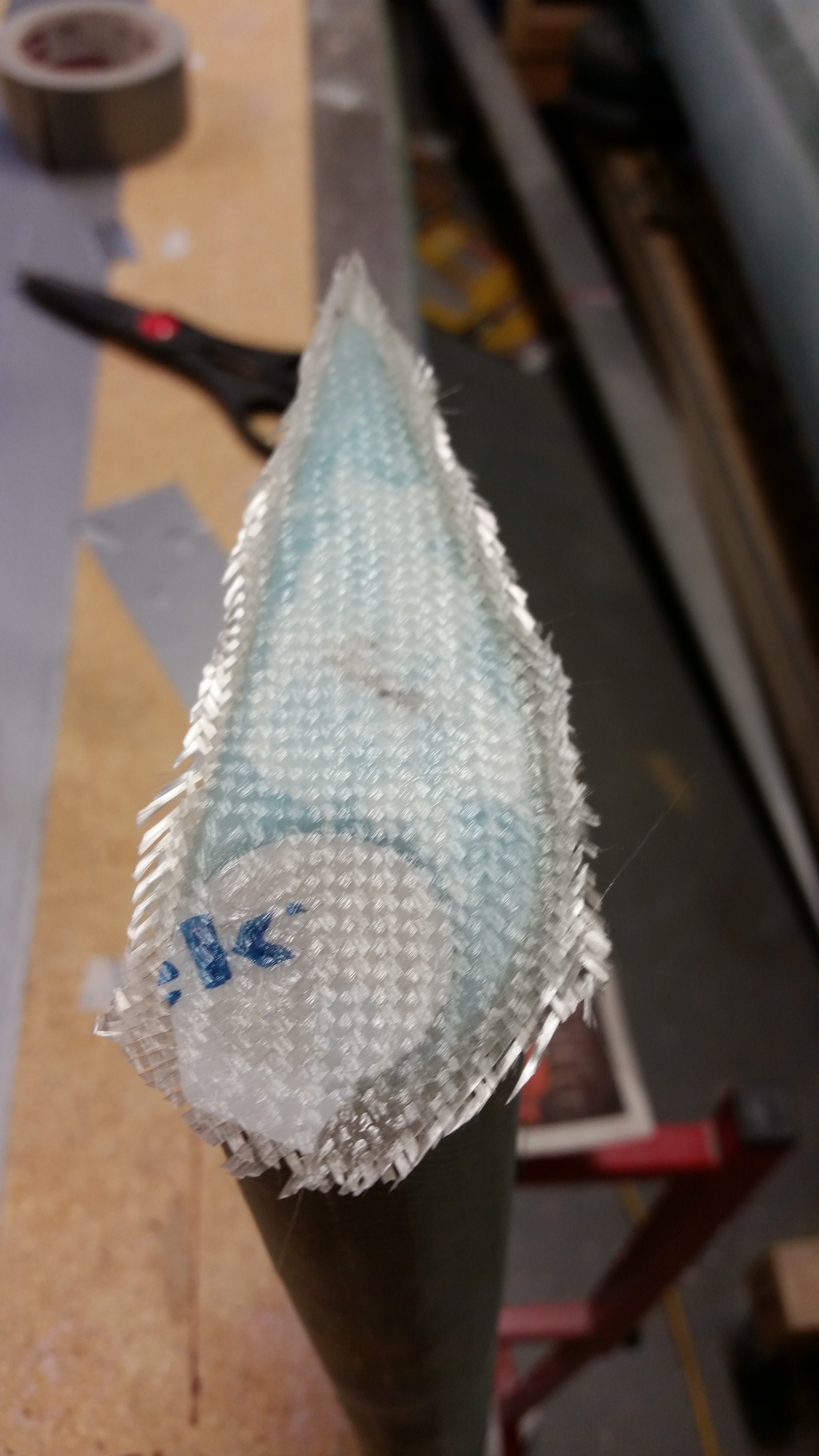
I stood the elevator up on end & cut the foam to create a wedge shape near the glass for the flox corners.
I grabbed a piece of scrap BID and cut it to roughly fit the end of the elevator.
I then mixed up some epoxy with fast hardener, made some flox for the corners & some micro for the foam. I then laid up the 1 ply of BID, trimmed the glass a little and let it cure.
•••
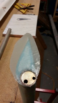
14 November 2015 — I started off today by trimming the elevator 1-ply BID glass that I laid up last night. I never made it back down to razor trim, so thank goodness it’s only one ply. I then sanded the edges flush with the surrounding top & bottom skins. I also had to cut out the glass over the NC-6 insert, and while doing so thought I should have stepped out of my paradigm and just glassed over all of it. Oh, well, a few more minutes and I had what you see below.
I then turned my sights first on sanding the rough spots of the LE, and I then pulled the peel ply and sanded the TE.
I took my German Praktiker special hand saw and cut the channels for the hinges. After the major cut, I cleaned up the channels with a razor blade and removed the duct tape over the hinge pin holes.
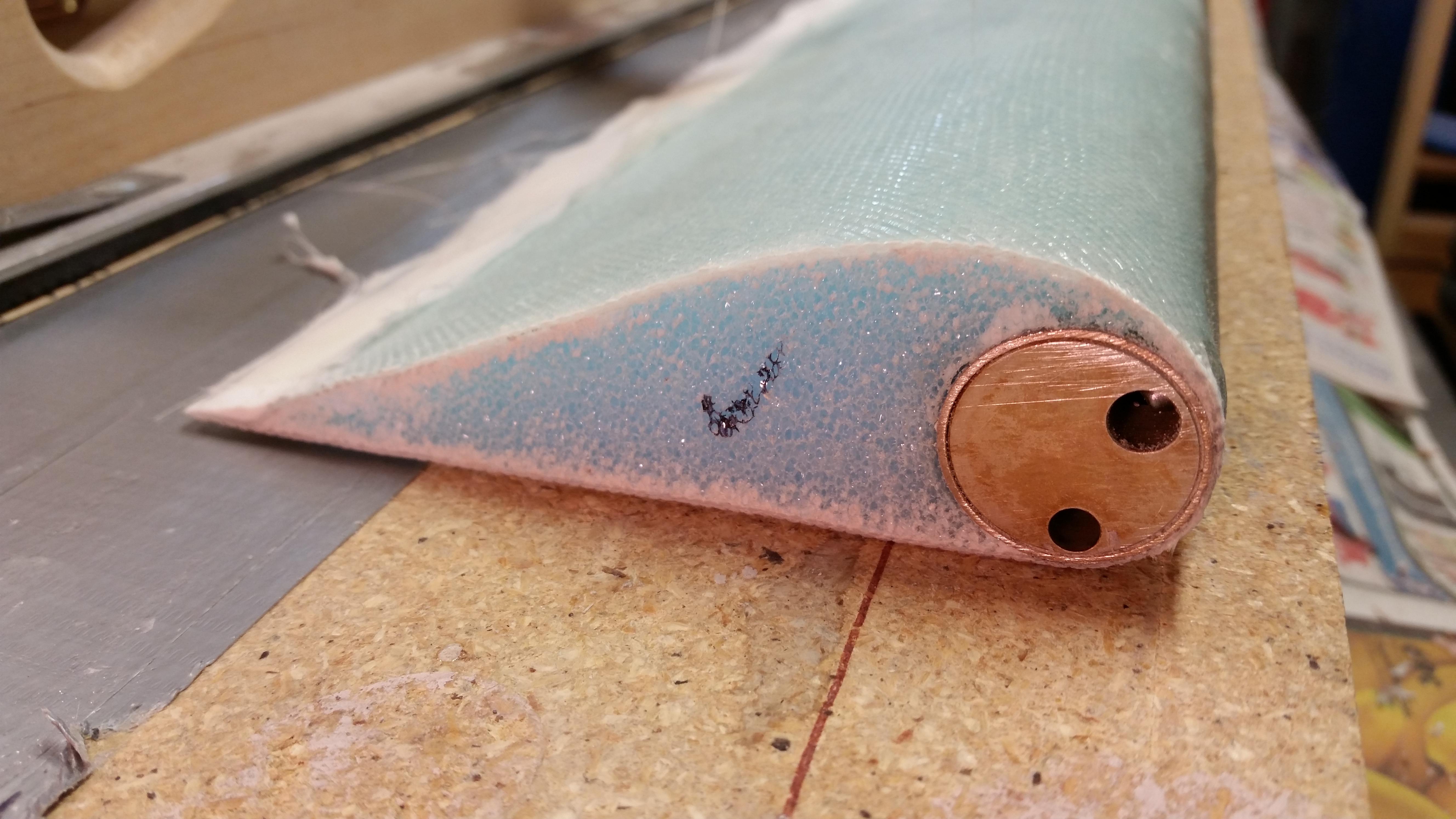
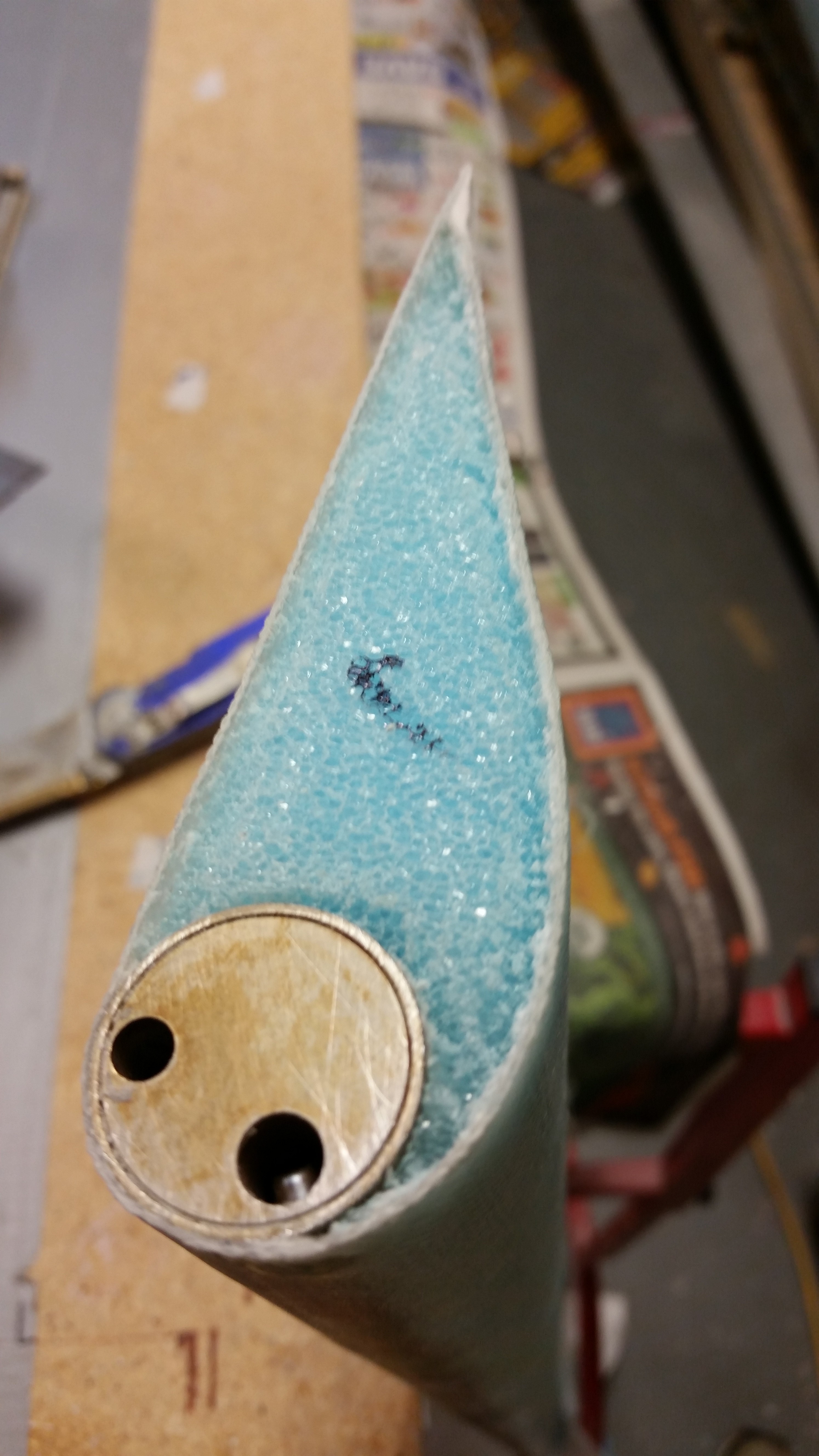
Below is a shot of the ancillary clean up, including the two hinge channels, the set screw hole at the close end and the torque office attach bolt hole at the opposite end.
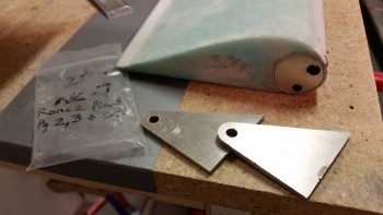
With the elevator pretty much completed, I turned my sights on the outboard elevator weight. I marked up a new foam spacer on the H100 foam piece I have on hand. I then cut it out and shaped it with 36 grit sandpaper.
I worked for about 10-15 minutes to get the foam spacer shaped properly, and then floxed the weight & foam spacer in place using the templates. Now, interestingly enough the plans say that you can use 5-minute glue, but of course I didn’t think of this until I had a batch of flox mixed up and of course I just bought some last week.
Oh, well, I just had to wait a little bit longer to glass it with 2 plies of UNI.
A few hours later I cut out 2 strips of UNI and laid them up around the outboard elevator weight as per plans. I then peel plied the layup before heading out for the evening.
When I returned everything looked good & cured. I pulled the peel ply, razor cut the glass, and then hit the edges very briefly with sandpaper. Here’s the end result.
And with that folks, I’m calling the right elevator rebuild complete!
•••
18 November 2015 — After taking a long hard look at the left elevator I made the call to rebuild it. The plans say that you can sand the skin down to 1 ply of glass with no issues as long as the areas aren’t too big (around 2″ in diameter). I met this criteria, the weight was under control after the heavy sanding, but the skin felt just a little too soft in that there was just a bit of give in about 3 of the 5 thinly sanded spots. My gut told me that this was ok and met the “letter of the law,” but since I have a perfectly “perfect” elevator core from Eureka CNC on hand, my brain said the right thing to do was rebuild this sucker. I want to be clear, this wasn’t a decision borne of fear, but one of optimization. I simply want to be able to run this bird as fast as I want to, without worries yes, but the more complete the elevator skin is, then common sense dictates the less prone to structural failure if I do encounter any flutter.
So, I chose to rebuild.
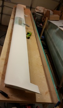
Here is the left elevator when I started this evening.
I began by removing the torque tube offset on the inboard side.
And then I removed the outboard weight.
If you remember, a while back I had a “moment” as I was floxing the inboard elevator hinge bracket into the canard slot. I had some type of exotherm issue where it spit out a good portion of the flox onto the hinge, torque tube, etc. The flox even bridged between all these parts and the fishtail area of the canard TE. I was heading out to meet my buddy Rob, so if I hadn’t found this issue and cleaned it up my life would have been hell for a at least a few days.
Anyway, that incident left some flox on the elevator torque tube offset that I never really noticed until today. After I removed the installing torque offset, I heated it up with the heat gun on high and then scraped off the dried epoxy.
This was the result of my cleaning:
Below is a shot of the “clean” left elevator with all the “add-ons” removed.
Then, as I did with the right elevator, I checked the gaps for hinge slot spacing with the hinge pin and NC7’s installed.
After I got my hinge spacing set and spacers cut to size, I made my first cut to remove the skin along the top of elevator.
And then the next cut along the bottom of the elevator near the tube. I used my trusty Fein saw to make these cuts (BTW, in my shop Fein=Harbor Freight!)
I then extricated the elevator tube from the glass & foam of the now “old” elevator core.
I cleaned off the old foam & micro with my razor knife in the first round of elevator tube cleaning.
Then, just as with the right elevator tube, I dunked it in a PVC tube full of solution. Only this time I soaked it in acetone vs. white vinegar since I wanted to get this tube completely cleaned by evening’s end. I figured acetone would probably have a bit more of a “bite” to it.
After a couple of hours, I removed the elevator tube from the acetone for its final cleaning.
•••
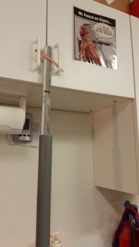
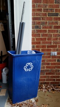
19 November 2015 — I started off today by sanding down the left elevator tube and then Alodining it. It was raining lightly so I let the tube soak in the PVC pipes just inside the garage door & out of the rain. As you can see, to keep the tubes upright I simply stuffed them into my shop recycle bin.
I really had to extend the soaking times of the tube in solution because the Alumaprep & Alodine is getting weaker every time I use it. I’ll have to assess what all I have left to Alodine and then buy some more when the timing is right.
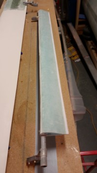
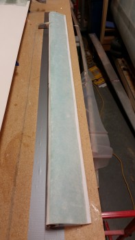
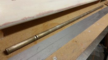
Below is a shot of the elevator tube after the Alodine dried.
Now, to get the left elevator foam core mounted on the elevator tube so that it matches the right elevator tube, especially the TE, I simply couldn’t build it as if it were a new build. Why? Well, when I originally drilled the elevator tubes to mount them to the torque offsets, which occurred at the same time with both elevators aligned, that action locked in the two elevators so that they were in synch and also ensured that the TE’s matched in trail.
Thus, I had to do a little reverse engineering in mounting the left elevator foam core to the left elevator tube. I had been pondering this quite a bit over the last week and finally decided to mount the elevator foam core with the elevator tube mounted on the canard, in conjunction with the other elevator tube, spool tube, torque offsets, etc. exactly as it would be in its final install. In using this method the first step would be to lock the right elevator TE in place, and then that would let me know where the left elevator TE needs to be.
Now, to take this one step further I wanted to mount the elevators to the canard with the canard in a nose down/TE up position. I pondered on this a bit as well and finally decided on a method:
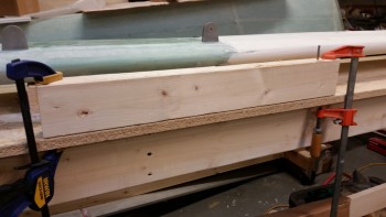
I started by measuring the distance between the LE and the canard mounting tabs, which was about 3-1/2″… obviously the same width as a 2×4. So I mounted a 2×4 to the work bench with clamps. I really wanted to avoid (at worst minimize) any damage to the mounting tab holes, so I used a drill bit as a smooth mounting peg on one side by simply drilling the bit into the 2×4 until the cutting edge disappeared into the wood. I then released the chuck and left the drill bit in the 2×4 (you can see this drill bit on the top right side of the 2×4).
Here’s a closeup shot of the drill bit as a mounting peg.
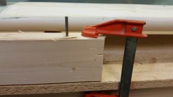
I then used a fine-threaded screw and covered all but the first 25% of the screw threads with electrical tape to mount the other canard mounting tab.
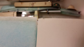
The first issue I noted is the mismatch between the TE of the new right elevator and the TE of the right swoosh tip. Now, I haven’t done specific measurements on the width of the of the elevator, so this may be a passing issue. Of course I made a note of it and it will have to be remedied in some fashion.
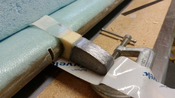
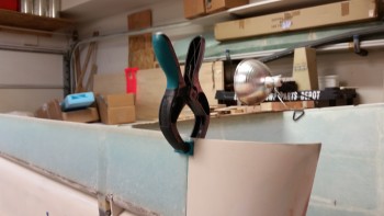
I then clamped the right elevator TE to keep it aligned.
Since this evening was all about fixing my elevator woes, it was nice to finally have something go right, as in I’m very happy that the outboard elevator weight fits perfectly into its notched home in the canard.
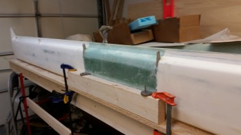
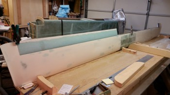
Here’ are couple shots of the canard with right elevator, et al, mounted.
Now, I have to admit that I just could not get either of the hinge pins into the inboard tube hinge points. I finally unmounted the canard, laid it flat in its normal right-side-up position and with a little firm coaxing and twisting with vice grips those suckers slid right in. On the bright side I guess it’s nice to know that they’ll go in when the plane is right side up. It would suck if it was the other way around! Yuk, yuk!
I then pulled out the second set of elevator foam cores that I just recently got from Eureka CNC.
To check how square the ends of these foam cores were I placed them end to end.
I then measured the paired cores and marked a line at 53″. I then cut the second foam core and confirmed that the two combined cores equalled 53″.
To keep the mess on the canard to a minimum, and to also keep the micro’d left elevator core as straight as possible, I decided to only micro the smaller of the left elevator foam cores pieces onto the tube. To start, I mocked up that smaller piece as you can see below. It fit perfectly and very snugly.
I mixed up some micro and micro’d on the smaller piece of the left elevator core. I ran a line from the right elevator TE to match the left elevator TE as closely as possible in trail to the right side.
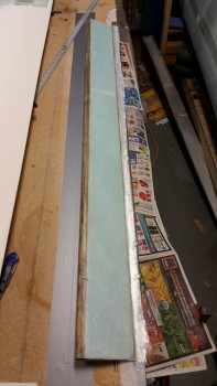
Here’s a wide angle shot of the left elevator core piece installed.
And a shot from the top side of the canard.
I let the micro cure for about an hour before dismantling the elevator assembly. With the smaller elevator core piece micro’d securely in place, I then merely mounted the remaining elevator core with micro.
And then weighed down the elevator core, specifically the TE.
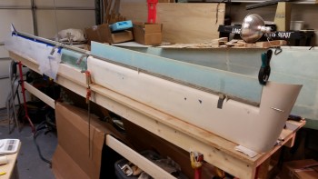
Here’s a shot of the curing left elevator core micro’d to the elevator tube, and a shot of the entire canard back in a “normal” state.
•••
20 November 2015 — Today was still all about finishing the left elevator rebuild . . . (big sigh!)
I was pleased to find no nasty surprises when I took the sandbags off the foam elevator cores. So far my evil plan is working to get the elevators to align.
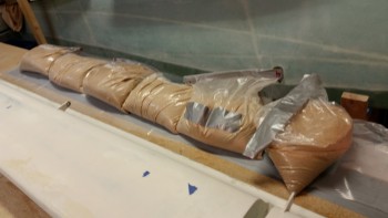
I started off by taping up all the openings on the elevator tube to keep the epoxy out of all the important orifices.
I then covered the top of the elevator foam core with patches of foil tape, hit each one with a drop of 5-min glue, and then mounted the elevator upside down on the work bench. I weighed down the elevator with sandbags, favoring the LE side.
Although tough to see in this pic, I remembered to slightly sand the area where the outboard weight UNI will reside on the bottom face of the elevator.
After my work call, I then laid up the 2-ply UNI elevator bottom skin.
The first pic is a fuzzy shot of the elevator bottom layup when it hit its “green” stage (trust me, it looked FAB-U-LOUS! haha!). I then razor trimmed the elevator.
Then, to let the glass cure even longer, I took the opportunity to run down to Home Depot to grab some 5/16″ bolts to attach the fuselage saddles to the fuselage dolly cross struts. While out, I called a good buddy of mine and ended up on with him for over an hour. This came into play since later in the evening I simply ran out of time… to make noise!
After I got back home, with the elevator skin cured more, I pulled the peel ply off the outboard weight mount area.
I then popped the elevator off the work bench. The pic below shows why I love using the foil tape so much. It holds incredibly well, but all but one of the pieces of foil tape stayed on the bench. Again, the top of the elevator foam core is clean … without any divots!
I trimmed the foam off the elevator TE, but I couldn’t finish the job because it was late and I didn’t want to make a lot of noise with the Dremel Tool. So instead I prepped the entire elevator to skin the top of it first thing tomorrow morning.
I then sanded the glass edge on the LE to provide a smooth transition for the top skin.
I also sanded the depression for the outboard elevator weight on the top foam core.
With all the prep actions completed for laying up the top elevator skin except for clearing the TE glass of all the foam & micro gunk, I turned out the lights and called it a night.
•••
21 November 2015 — After using the Dremel tool on the elevator TE to clean off the foam & micro to ensure a good glass-to-glass bond, I applied foil tape to the bottom of the elevator and instead of Bondo I used 5-min glue to secure the elevator to the table.
I weighed down the elevator as the 5-minute glue cured.
I re-vacuumed the top of the elevator after removing the sandbags and then whipped up some micro and applied it.
Here’s a shot after I completed the 2-ply UNI layup.
A close up shot to show how dry the layup is … can you tell?
After a couple of hours I applied dry micro to the TE and then covered the micro with a 1″ wide strip of peel ply.
•••
22 November 2015 — I started out today by trimming the foam around the inside edges of the glass skin on the outboard end of the elevator. This foam removal is to allow for flox to be applied to replace the foam in the areas around the perimeter and thus create a “flox corner” for strength.
Unlike the other side, where I taped up the NC6 and then worked a fair amount to get the cured glass off of it, this time I simply cut the glass out ahead of time using a 1″ round tube as a template on a pre-pregged ply of BID.
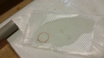
Here’s the prepreg after I cut out the 1″ circle.
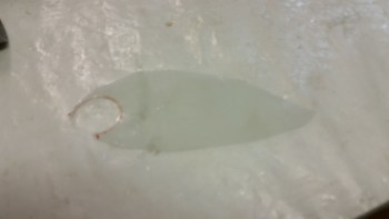
And here’s the layup with the top piece of prepreg plastic still in place.
Here’s the layup set to cure.
Quite a few hours later I returned and razor edged the elevator end layup. Since it was pretty much cured, I sanded the corners of the layup to smooth everything out.
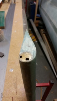
I don’t have a pic of it, but I did spend a little time removing all the protective tape from the various holes in the elevator I cut the glass covering the hinge tab slots, and then drilled out the holes on each end: one for the set screw and the other for the torque offset bolt, respectively. I also sanded the LE a bit to get everything smooth & even.
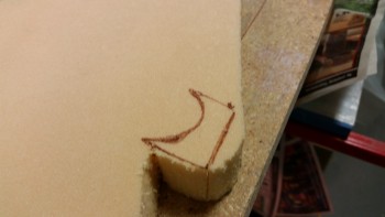
Here’s a shot of the end of the elevator, and the contour template in place as well.
My last act of the evening (besides some research) was to re-attach the outboard elevator weight with flox. On this side the foam wasn’t too bad off, so I reused it. I did add a small crescent moon shaped foam spacer to help fill in a gap where it met the LE. I mounted it to the elevator with flox made with fast hardener.
•••
23 November 2015 — The left elevator rebuild is complete!
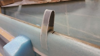
I finished the left elevator rebuild by laying up the 2-ply UNI strip layup around the outboard elevator weight.
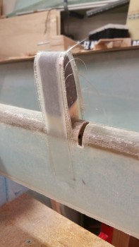
I then peel plied the layup.
Here’s a shot of the completed left elevator . . . hoo-ah!
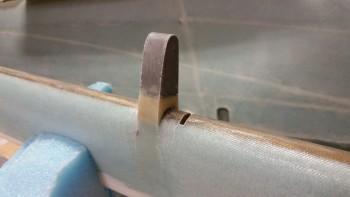
And here’s the trimmed outboard elevator weight glass.
•••