
Chapter 6 — Step 1 of 2
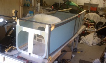
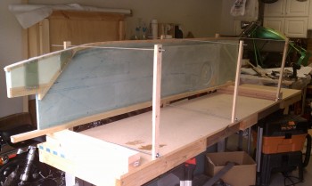
26 May 2011 — Fuselage mock up with bulkheads and fuselage left and right sides.
•••
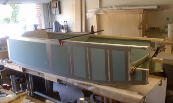
5 June 2011 — I started the process of assembling the fuselage. I first made large clamps out of 1×2’s and long threaded rods to hold the fuselage sides together, and tight against the bulkhead sides. Note the bolt holes for the main landing gear mounts at the aft end of the fuselage. ↓
•••
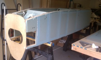
21 June 2011 — Today is a huge day for the Long-EZ build. The fuselage is now one piece after a long haul of assembling the fuselage. It was quite exhausting and seemed a lot more difficult than it should have been, but then again I did it by myself and it probably would have been much easier if A) I had prior experience, and B) I knew what challenges to expect in aligning everything!
_____________________________________________________________________________________________
During the months of June & July 2011 I was prepping to move to Germany, so admittedly I was rushed in trying to get the fuselage skinned… it didn’t happen. Also, the number and sequences of pictures suffered a bit as well since I was trying to get Chapter 7 finished as quickly as possible.
_____________________________________________________________________________________________
Chapter 6 — Step 2 of 2: Contouring & Installing the Fuselage Bottom
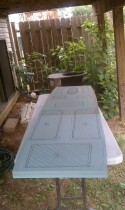
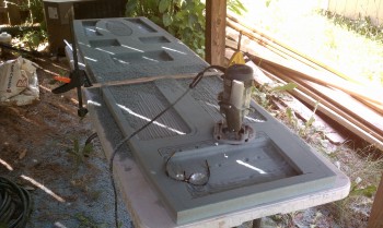
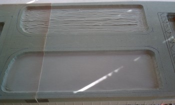
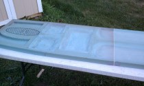
23 June 2011 — I micro’d the two thick 1-3/4″ fuselage bottom Divinycell foam panels together last night (22 June 2011), and then once dry put it up on top of the inverted fuselage. I then marked the inside bottom of the fuselage bottom and marked up the areas to be cut and shaped. Once the outlines were in place, I took the fuselage bottom out back and began the very messy process of routing out all that blue foam. Once I got the major portions of the blue foam gone I carved the divots in the fuselage bottom by hand, sandpaper and some Perm-a-grit tools.
The fuselage bottom is shaped somewhat like a boat, or a football I guess. Although my fuselage is shaped a little differently than the plan’s shape, it really doesn’t matter with the steps used to figure out the outline of the fuselage bottom.
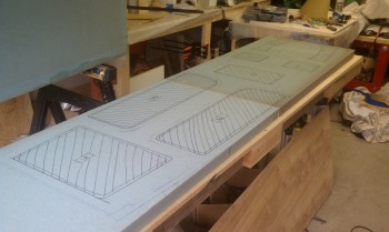
The fuselage assembly is simply turned upside down and the fuselage bottom is placed on the bottom (which is now the top) of the fuselage and positioned equidistant from each side and abutted to the front bulkhead F22.
Once the fuselage bottom is in place, it’s weighed down to conform to the shape of the fuselage bottom.
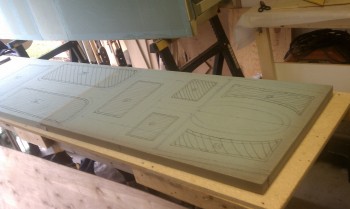
Then I climbed up underneath there with a Sharpie and marked the outlines of each compartment. Then the weights came off and I followed the dimensions spelled out in the plans to create the marked up areas that will be formed into its final shape.
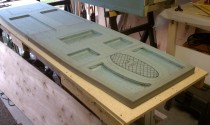
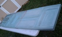
With the mark-ups complete, now it’s time to actually cut out the outside shape of the fuselage bottom. Once I got the outside shape cut, I took it outside to start getting all that foam out of the marked-upped areas.

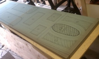
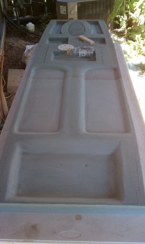
There are specific depths for each area, and obviously all the transitions need to flow together smoothly. The process definitely takes a bit of time, and it does get fairly messy with all that blue foam!
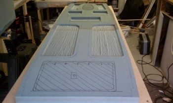
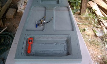
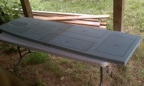
The process continues: Removing lots of foam, creating a gross outline of the individual areas, transitioning and then smoothing it all out. I started from the rear half and moved forward.
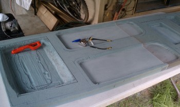
I started this step mid-morning and tried to stay in the shade, not just because of keeping the sun off the foam, but because it was pretty darn hot as well. I worked well into the late afternoon and slowly nugged my way through this beast!
•••
_____________________________________________________________________________________________
CHAPTER 6 WRAP-UP FOR THE VIRGINIA PHASE:
25 June 2011 — I don’t have any pictures of the remaining fuselage build efforts in Virginia before I left for Germany. Maybe that’s a good thing. I put the newly shaped fuselage bottom on the upside down fuselage and weighed it down. I then made what was essentially a sled with 1/8″ oak plywood attached to the outside of the fuselage bottom, and with three 2×3 stringers keeping its shape.
Once the sled was glued and dried, I flipped it onto the work bench. I proceeded to set up a large vacuum bag layup so I could pull the glass down into all those nooks and odd-shaped divots. I can say this was my first layup that turned into a true layup from hell! Everything seemed to be going well, until I realized I was NOT holding good suction on the vacuum bag setup. I tried for an hour or so to find and seal the leak, but no joy. I finally had to disassemble the vacuum bag setup and pull off all the plastic. I then worked the glass as quickly as I could, but the back end started curing funky on me.
I ended up just taking a razor knife and cutting straight across the fuselage bottom about 6″ behind where the front seat meets the lower fuselage. By the time I got all that done it was around 4 am and I felt OK about the front half, and there was nothing on the back end except drying epoxy on the foam surface. I let it cure and shipped the whole sled/fuselage bottom combo over to Germany… where the story continues!
_____________________________________________________________________________________________