
Chapter 18 – Canopy Latch Hardware
This page covers all the hardware required to secure the canopy (besides hinges & pneumatic canopy strut) after the physical construction of the canopy.
20 August 2016 — During the last week I have been doing some odd & end stuff on the build, much of it stuff I was never able to really put together before since I didn’t have all the pieces parts in the same location.
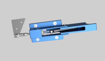
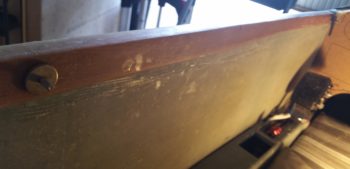
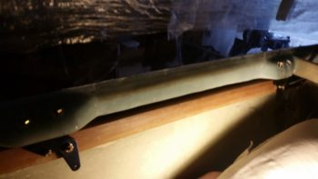
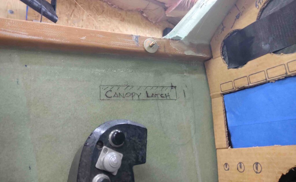
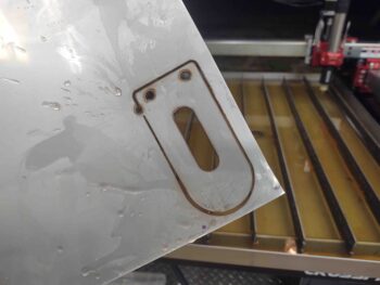
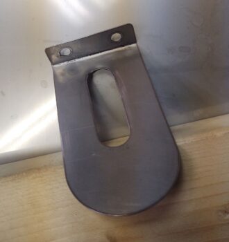
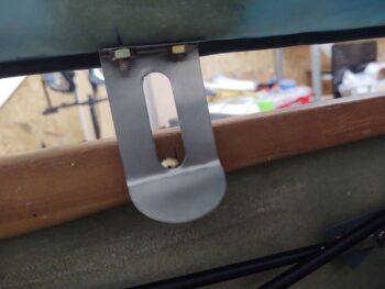
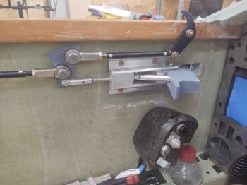
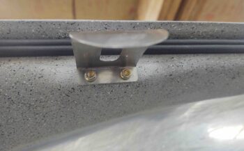
A note that I’ve had for a while in the middle of my electrical switch diagram states to account for the panel space required by the canopy latch arm that sticks out horizontally into the space near the throttle handle. I became acutely aware of how much space the canopy latch was really taking up when I sat in my buddy Marco’s Long-EZ specifically to note clearances, required reach to cockpit items/switches, and simple ergonomics. It emphasized that the note on my switch diagram truly had merit, and that I must indeed account for this most necessary but intrusive component (pic below is from Jack’s website).
Thus, back at my hacienda, I finally got around to pulling out the EZ-Rotary Canopy Latch kit that I bought from Jack Wilhelmson (eznoselift.com). I first (re-)inventoried all the parts to ensure I hadn’t lost anything over the years. I then did a quick (re-)review of the installation procedures to get a feel of what I was up against. My main current concern was of course the clearance with the instrument panel, and luckily with this setup the bearing block hangs down from underneath the longeron, and not straight out from the panel, thus giving me back the 3-4 square inches that I wouldn’t have been able to use on my instrument panel if I had installed the plans version of the canopy latch.
•••
26 June 2017 — I realized as I was making up a quick sketch of all the GIB controlled electrical components (with the addition of the LED lit fuel site gauges) that I should account for the canopy locking rod & latches. I stumbled upon a discovery that shows yet another faulty assumption on my part, and I’m not sure exactly how I missed it.
The bottom line is that I found that the midpoint canopy latch is supposed to be –as per plans– situated at the front business area of my roll bar. I played around with it for a while, but realized I just had to bite the bullet and will have to move the middle canopy latch about 1.4″ forward. I’ll probably adjust the aft latch a hair forward as well, but at least now I know. Amazing that just this nth order affect took me about an hour to track down (well, technically over 2 years to track down!).
•••
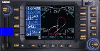
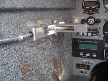
10 January 2018 — I started off this morning reading an email from my buddy Dave in OZ extolling some issues on placing the latch for Jack Wilhelmson’s RL-1 Canopy Rotary Latch system. Dave has too many interfering components, including the left knob on his Garmin GTN650, if he tries to put it in the traditional location just in front of the left side of the instrument panel. Just as a point of note, that was seriously a big primary reason why I went with the GNS480: no left knob except the on/off/vol knob, which is still however my own limiting factor for moving my RL-1 latch up as close to the panel as I’d like.
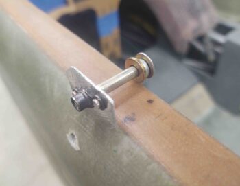
Well, curiosity got the better of me, so I grabbed my latch and mocked it up… I was aiming for the plans’ ~4″ in my head and mocked it up quickly, realizing immediately after I took the pic below that the longer lever doesn’t reach forward as I have it in the pic, it only just travels between the 7’ish to maybe 1 O’clock position (as I understand it).
I pulled out the installation manual and had in my notes to move the whole canopy latch shebang 1.4″ forward to allow clearance at the rollover assembly and also for the throttle. Dave’s solution looks to be mounting it mid-strake opening, thus turning it into a center controlled latch with the small catches forward and aft of the main latch, where as obviously both are aft on the plans style latch.
Since I can’t really do what Dave is doing (since Dave is building his Long-EZ to fly around the world, he has no fuselage cutouts into the strakes… the fuselage sidewalls are the interior walls of the fuel tanks), my issue becomes one of tight tolerances and clearances.
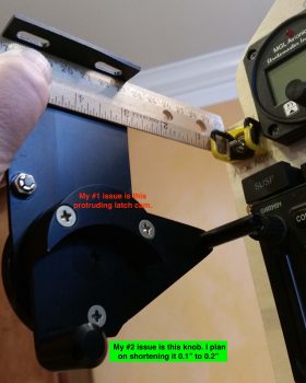
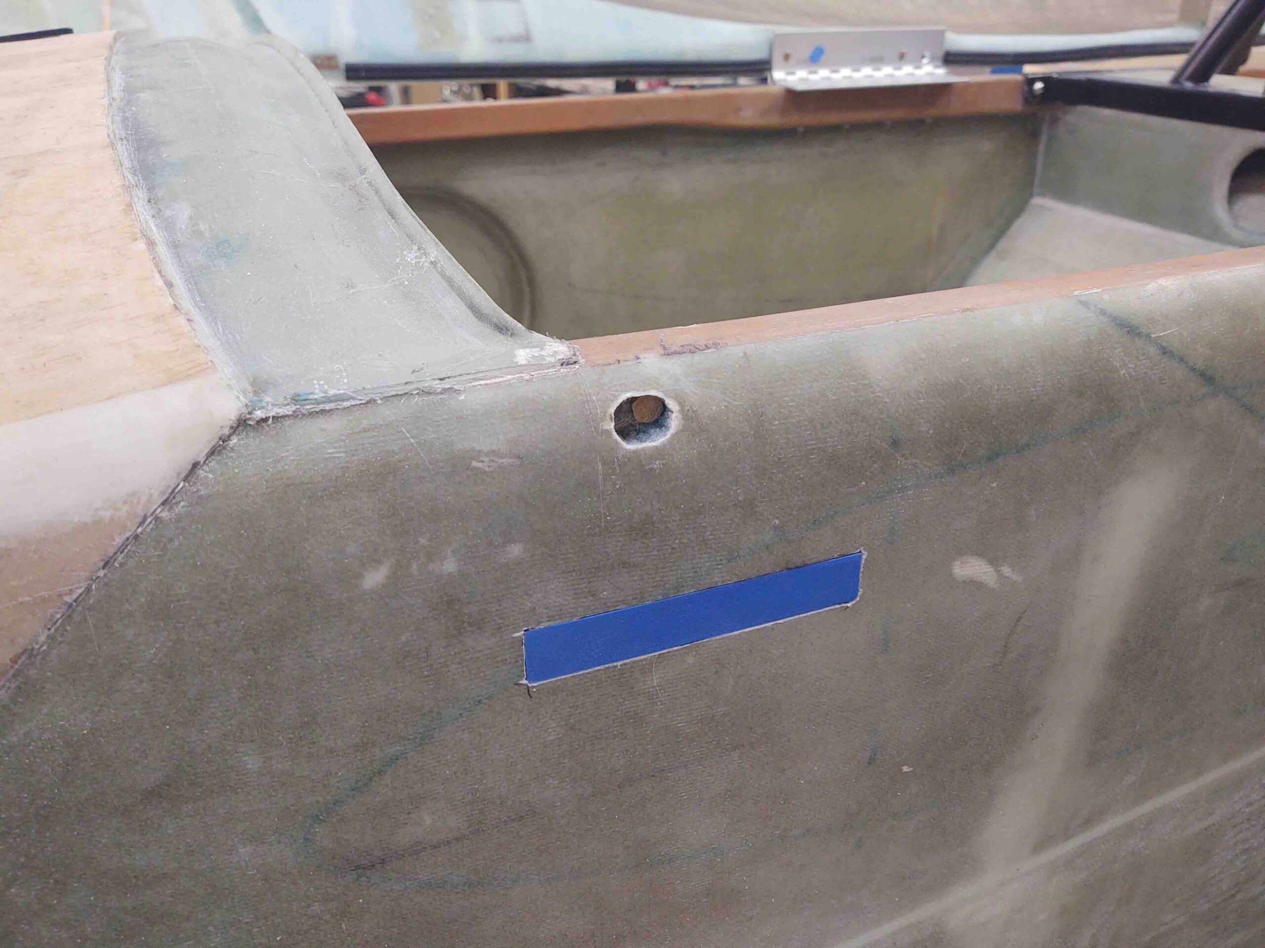
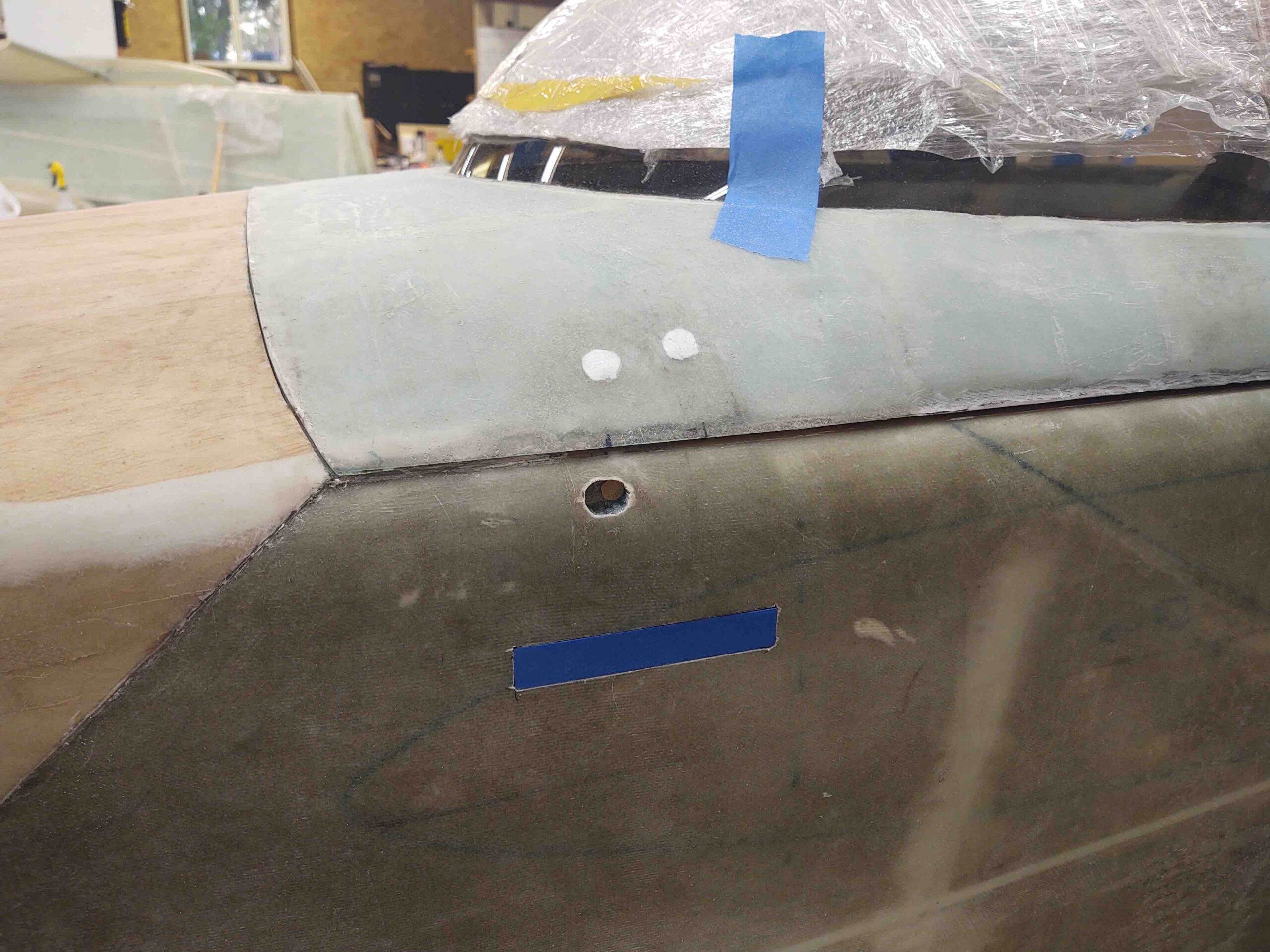
Although the cardboard cutout I made as positioned below is ~1.4″ inches forward (F.S. 42.6) of the plans’ position (F.S. 44), allowing clearance for the throttle, this position has the short fat rotary latch knob hitting my GNS480 on/off/vol knob. Moving it aft about 0.2″ provides clearance for the knobs, but only gives me about 1/4″ clearance from the outboard top edge of my CURRENT WOT throttle position to the robust, square-edged latch cam I note in the pic above (noted as “#1 issue”).
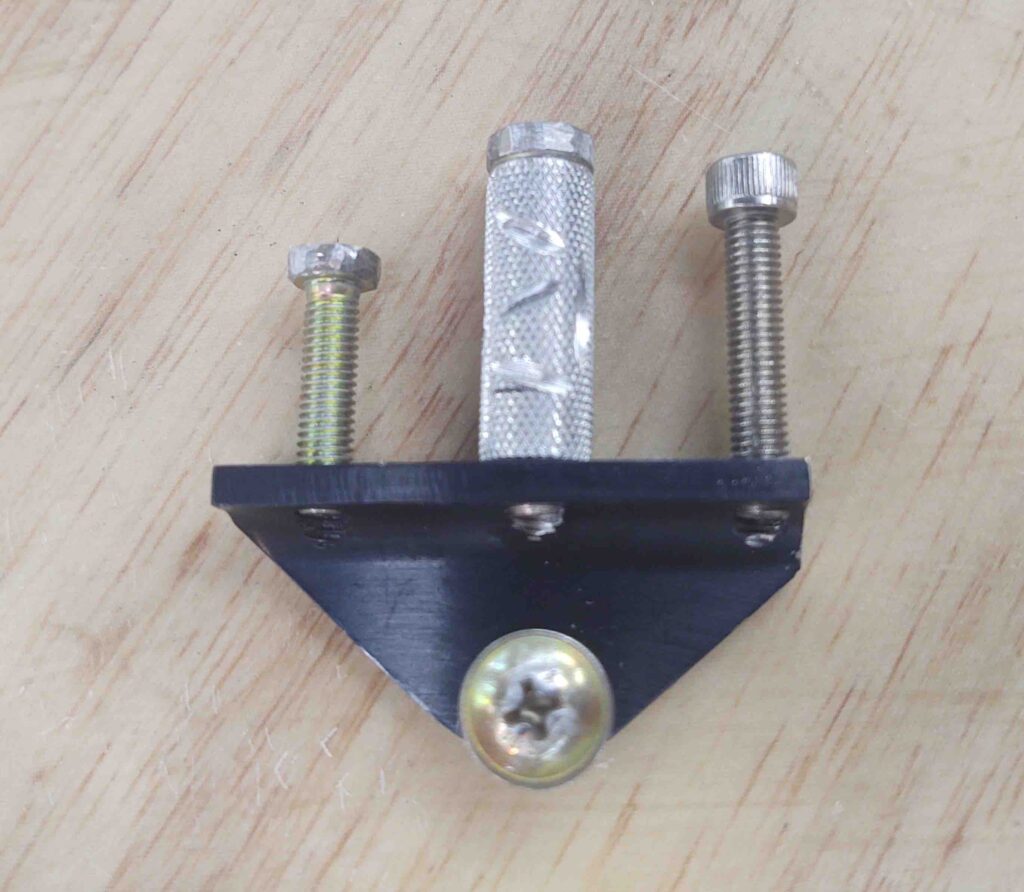
Thus, I provide Wade’s 3-point plan for eaking out just enough room to make this work:
1. Ensure the rotary latch assembly is driven as far outboard up against the sidewall as possible when mounted to better provide clearance between the latch cam (top pic) and the outboard edge of the throttle handle. BTW, the throttle handle’s outboard edge aligns vertically very closely with the inboard edge of the longeron (if you drew a line or strung a plumb bob and viewed it from top/aft/front), so there is clearance… but I just want more for my poor pinky! Also, regarding the clearance between throttle and canopy latch, the real issue is only during T/O and climbs at WOT.
2. I still need to drop the throttle down when I construct the new throttle lever. With the canopy latch position required to be a hair aft of where I originally wanted it, I may cheat a bit and drive the throttle inboard say 0.1″, and mount it lower (the handle, not the quadrant) the furthest it will go comfortably.
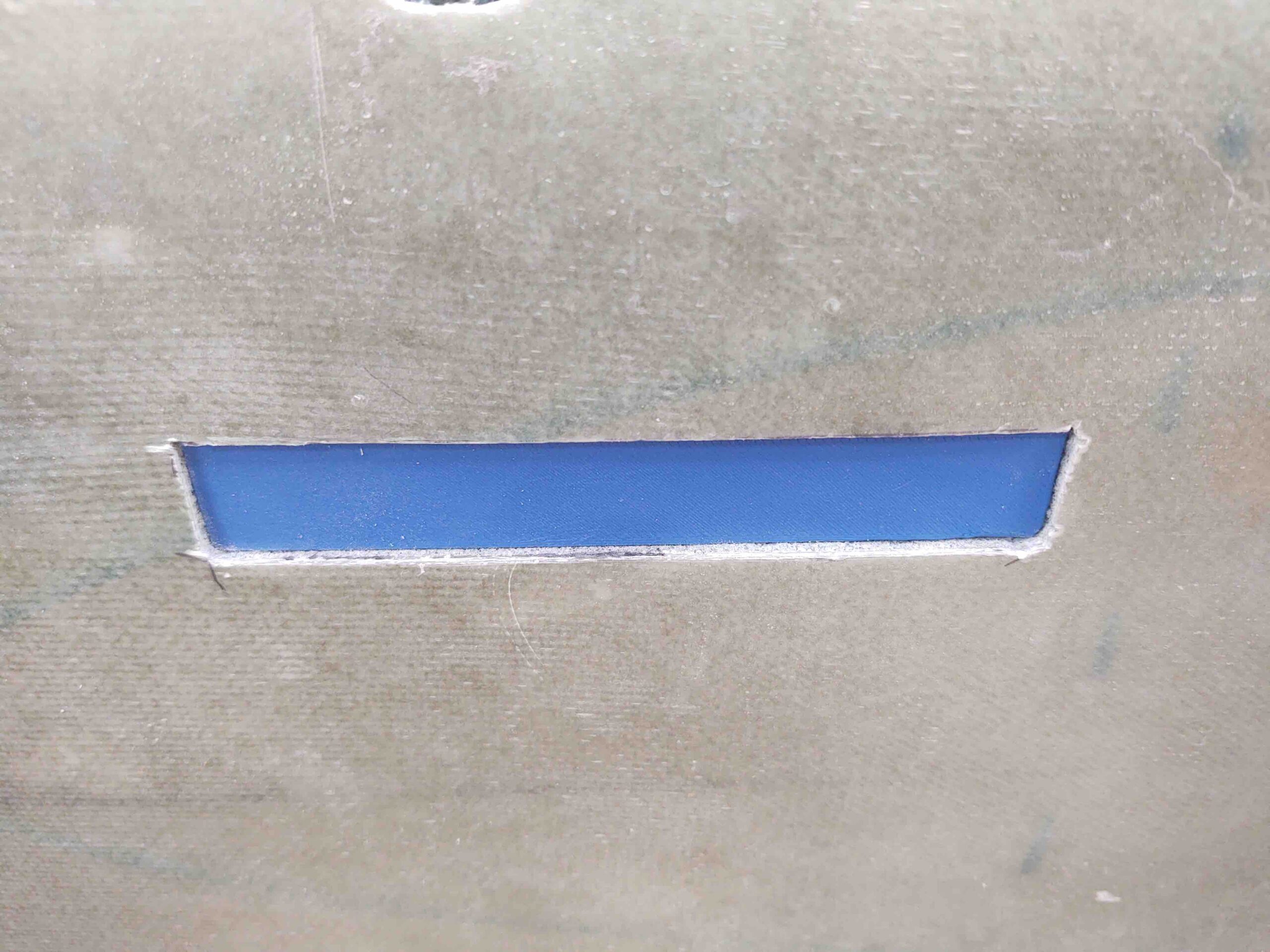
3. There’s approximately a 3/4″ gap between the front of the rotary latch’s smaller fat knob (depicted blue above) and the GNS480 face when the rotary latch is locked and closed. Again, this is approximate of course since I don’t know the exact resting position of this knob, but it is close to what I have shown above. This shorter latch knob will also just barely clear the bottom front edge of the “PWR/VOL” knob. However, since I come in at a slight angle from the right anyway to push the CDI button (XPDR button is inop in my setup), the short fat knob if left alone wouldn’t present a big problem. But by driving the rotary latch assembly as far outboard as possible AND trimming about 1/8″ off the bottom (outboard) of the knob to reduce it’s overall protrusion into my GNS480 op space, I should have zero issues for any 480 button-pushing tasks that may ensue.
•••
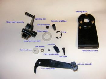
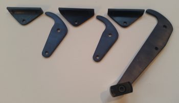
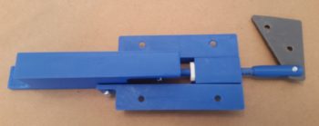
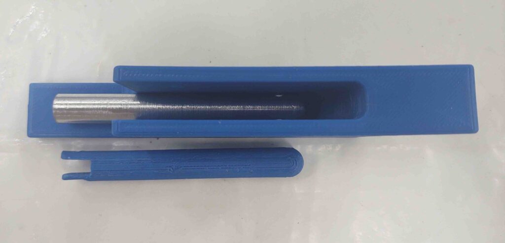
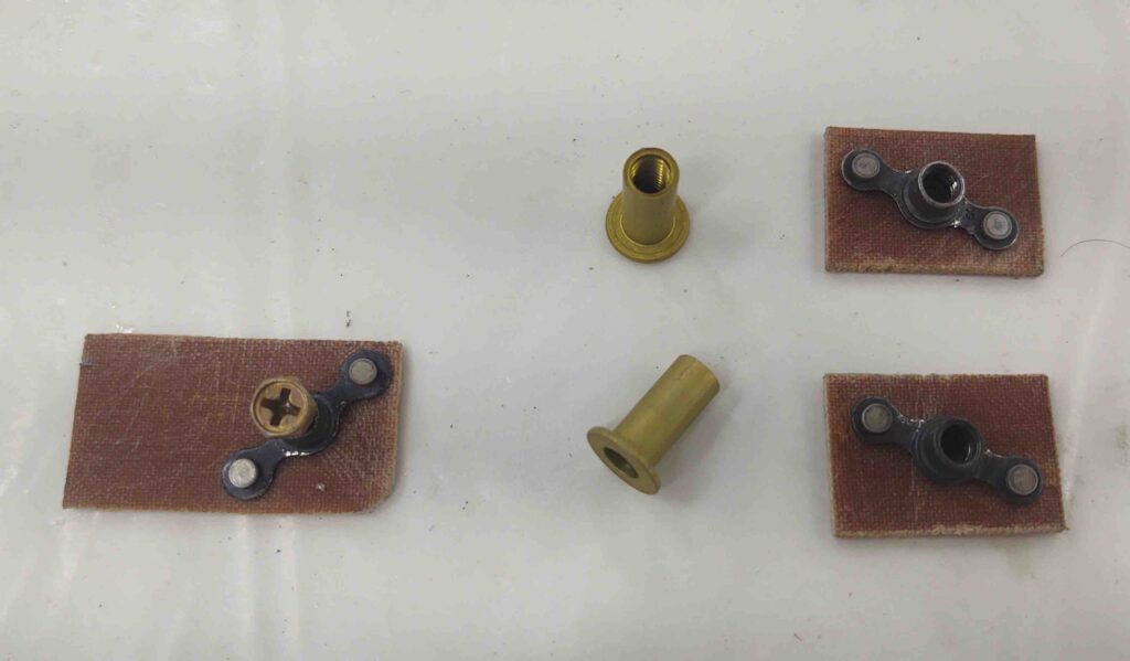
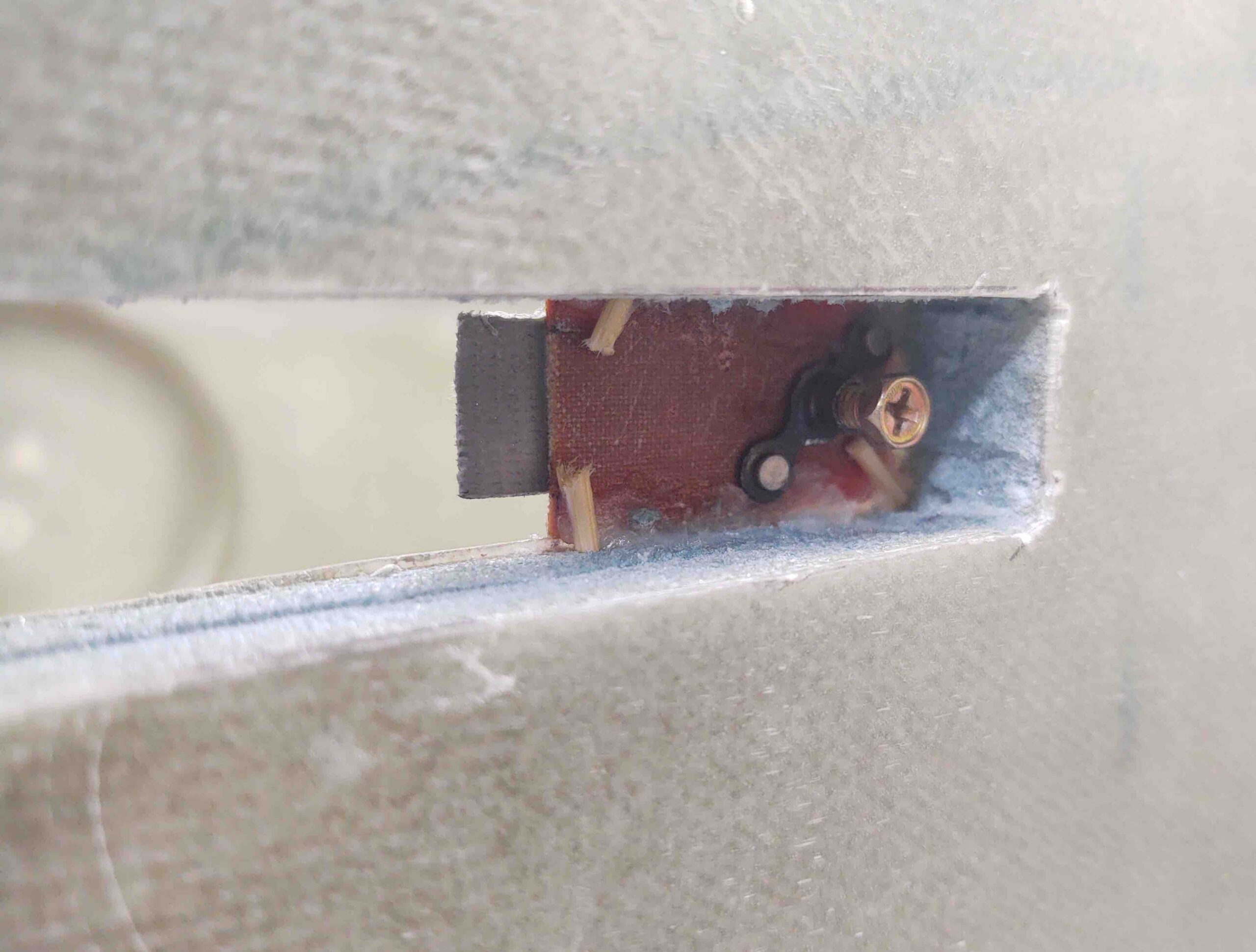
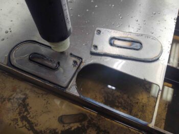
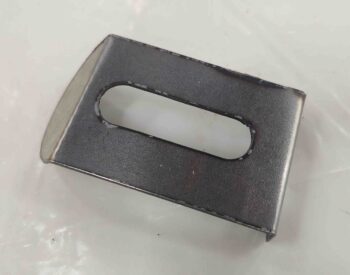
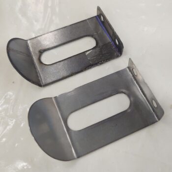
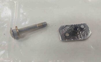
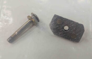
12 January 2018 — I started off today discussing a variety of issues via email with my buddy Dave Berenholtz, one of which was parts availability for the canopy latch system. I took the pic below of my Wilhelmson RL-1 rotary canopy latch components to add some clarity to my email and thought I’d include it here.
•••
20 March 2018 — Because of the issues detailed above, over the past couple of weeks I have decided to undertake yet another mod (I know, I know . . .!) and build a new canopy latch based on Mike Bowden’s design since his high horizontally-situated/activated latch works much better for my configuration (read: operating space) than does the rotary latch extending down in front of the left-side panel.
Although based primarily on Mike Bowden’s design, I will combine it with the forward latch catch manipulating features of the mystery Long-EZ that I somehow have a pic of, but have not been able to find who owns it or built it. Coincidentally, as I was compiling a buy list of all the materials I would need to construct this latch, I got a text from Mike Bowden… who graciously provided me a plethora of dimensions that I had asked him for regarding his canopy latch.
•••
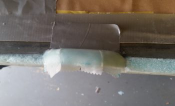
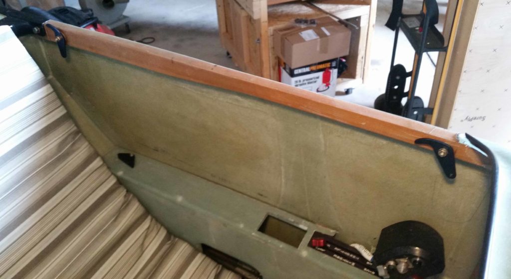
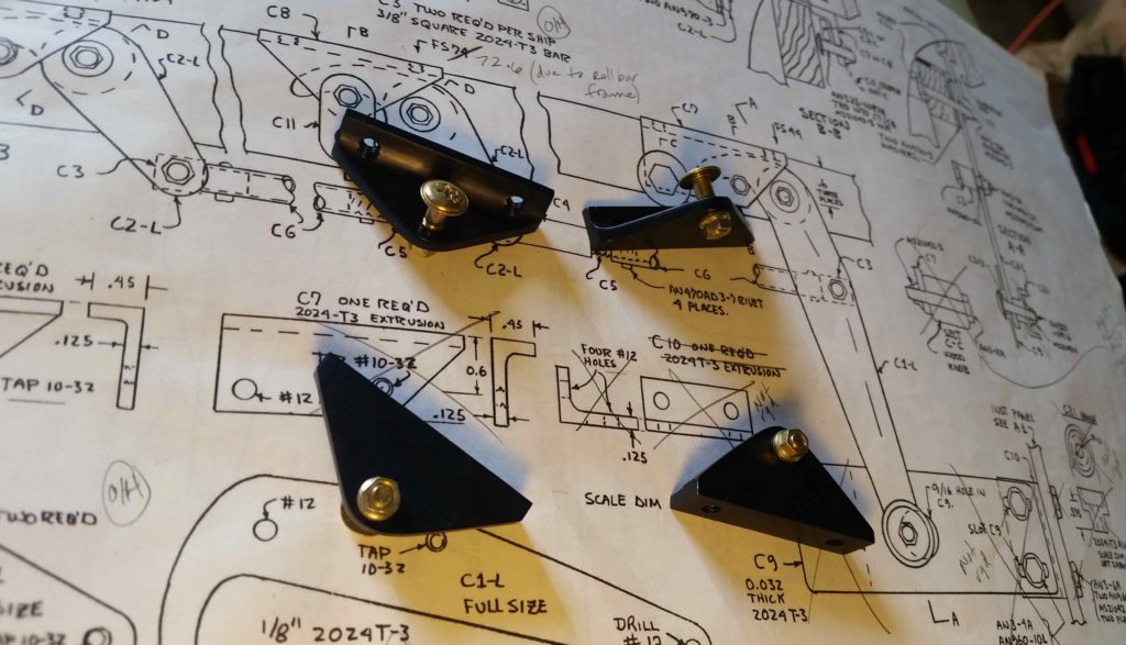
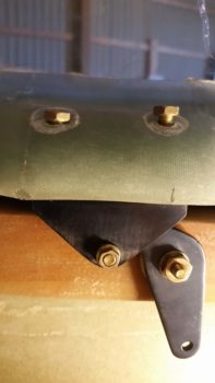
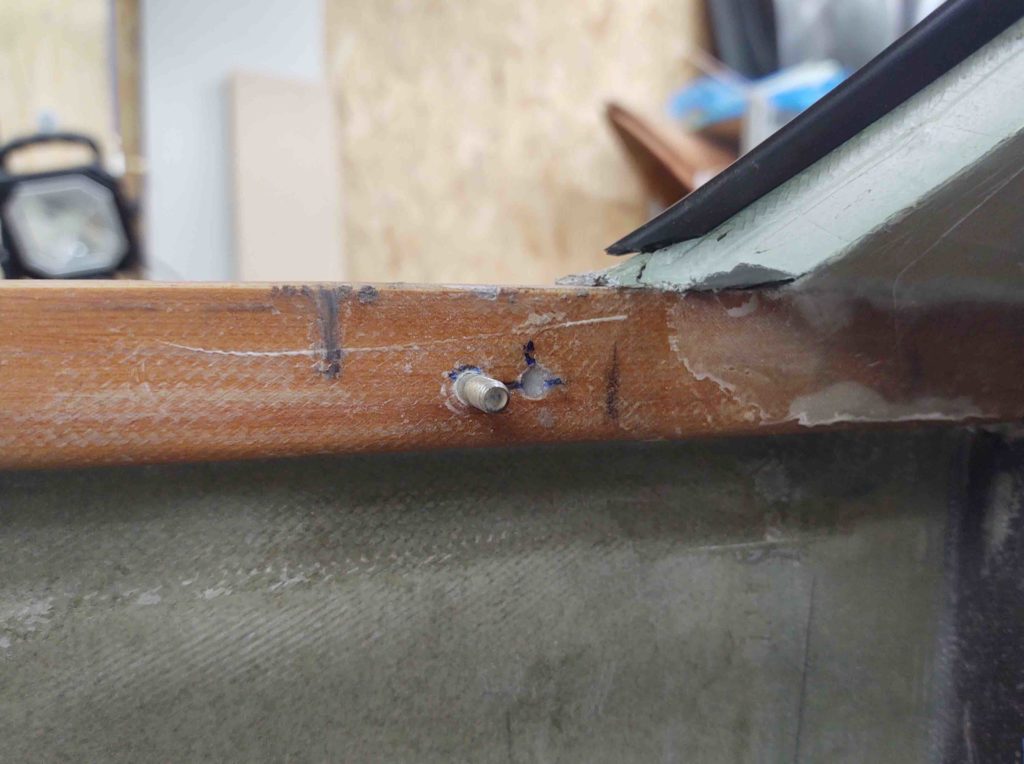
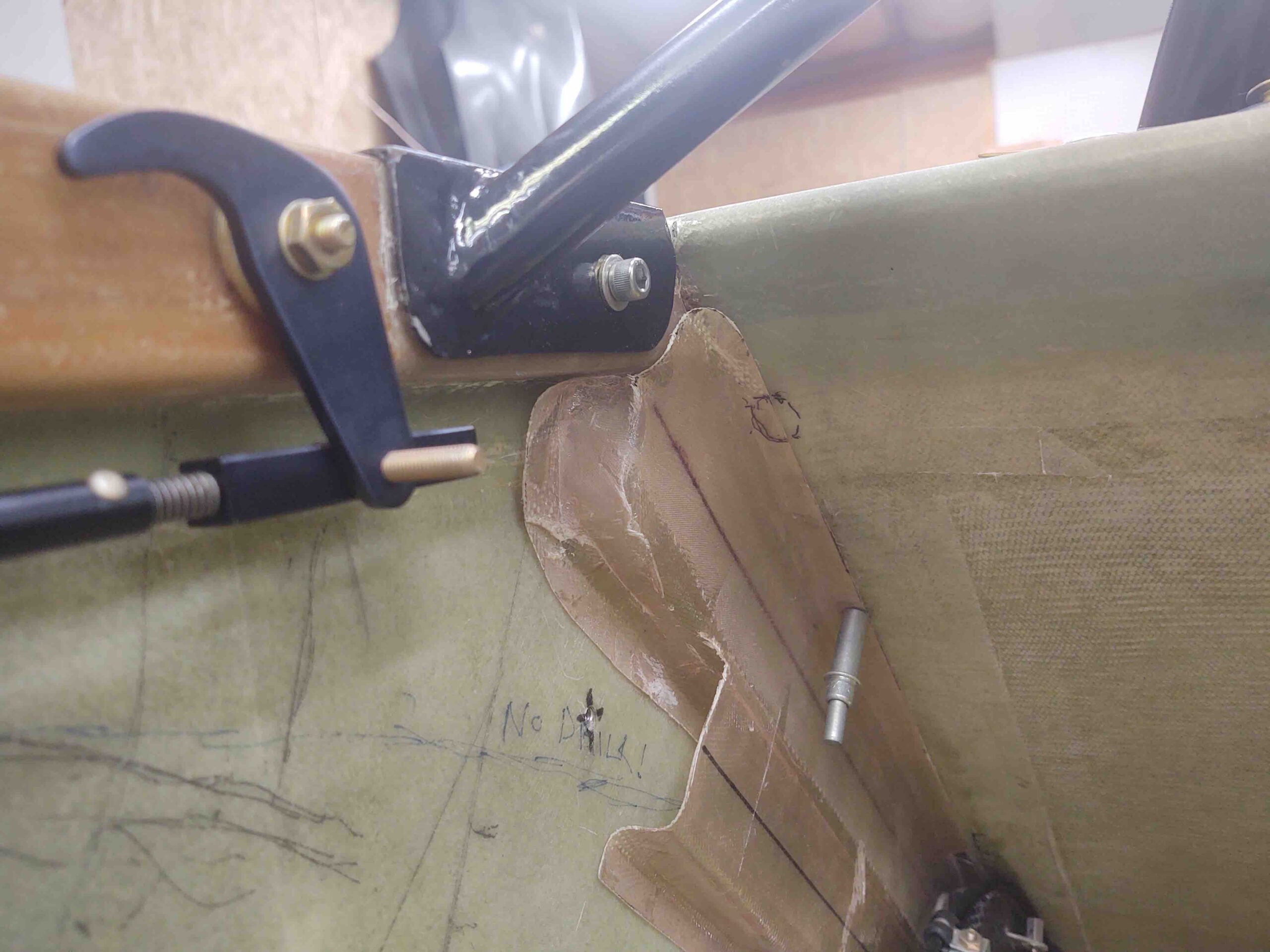
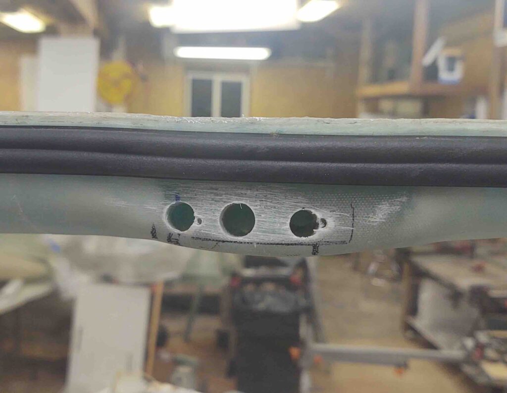
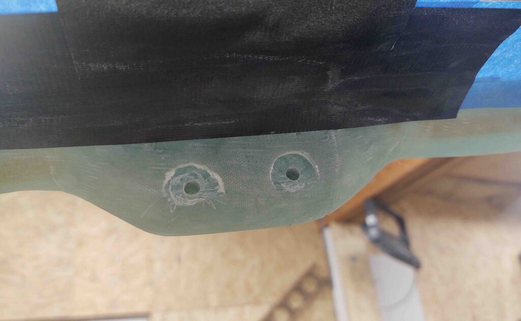
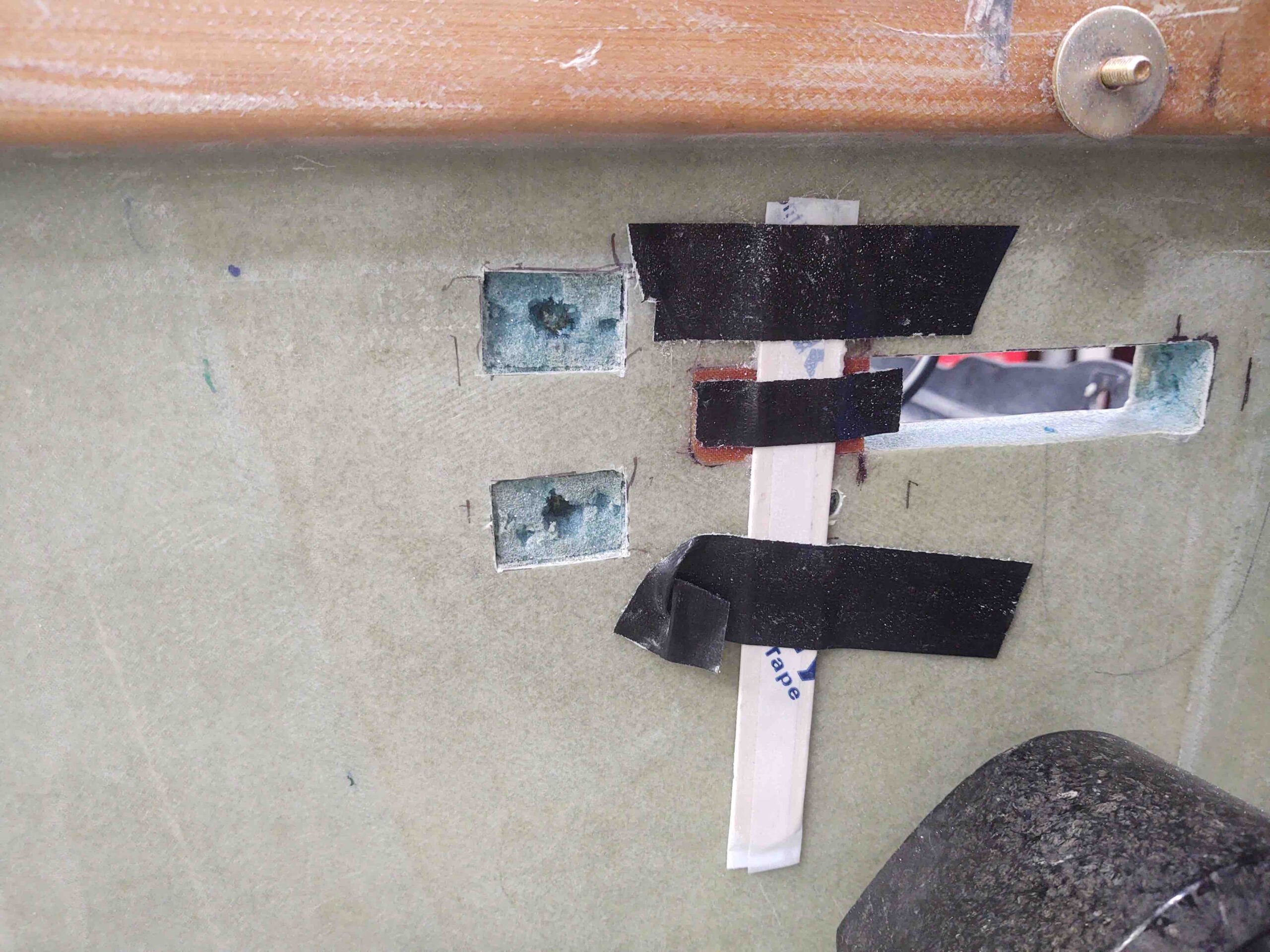
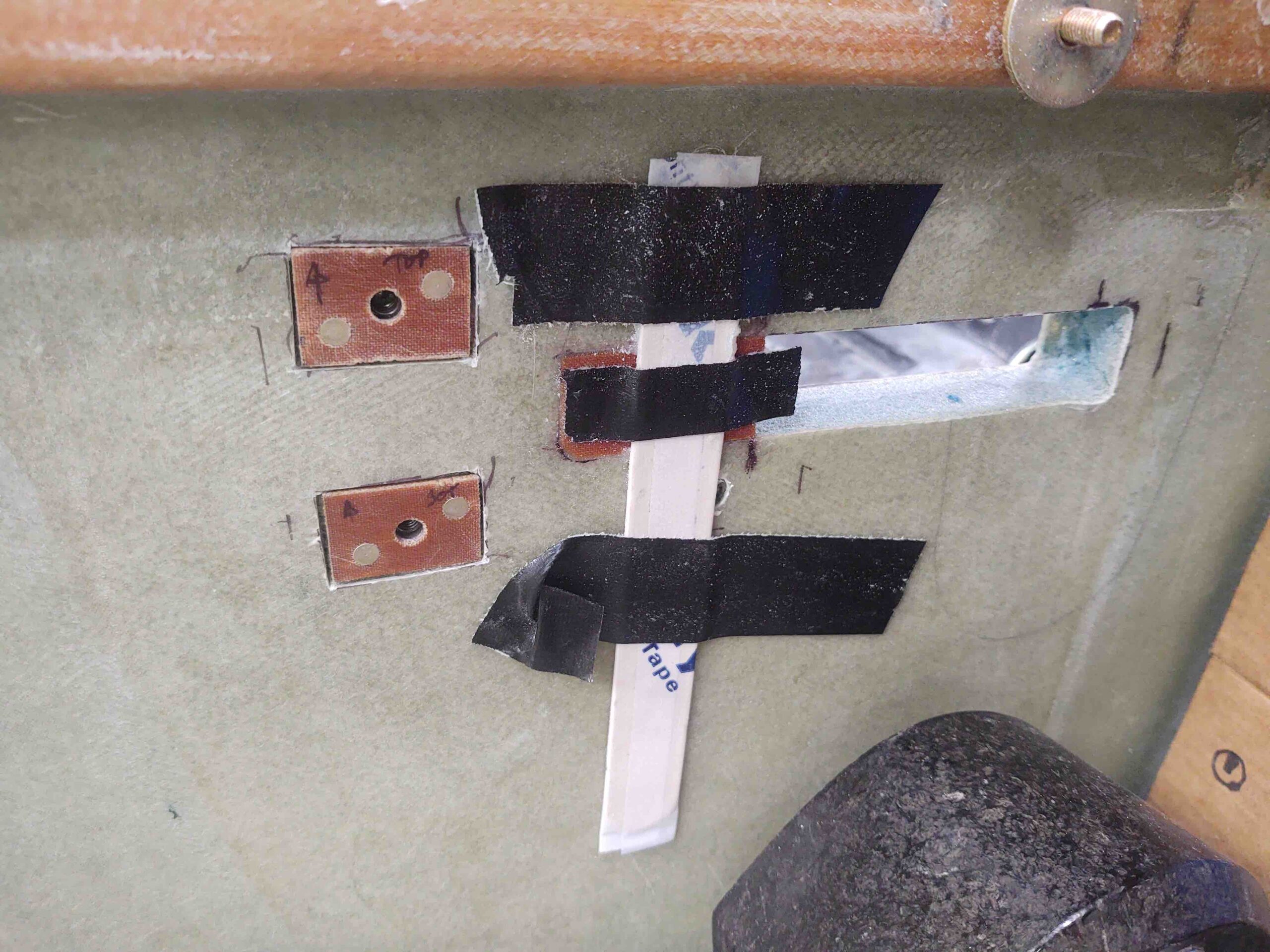
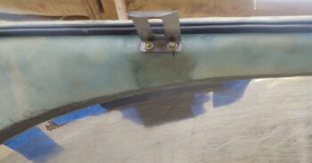
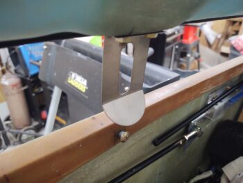
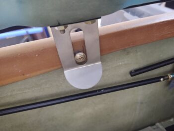
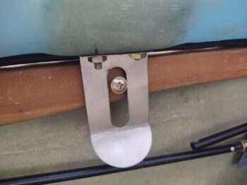
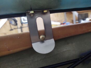
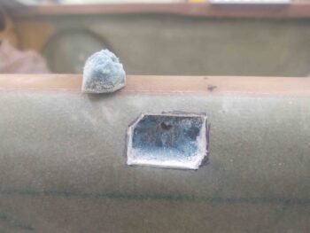
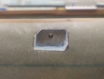
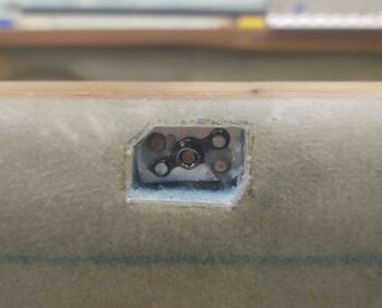
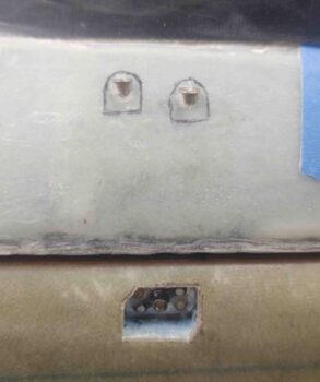
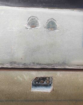
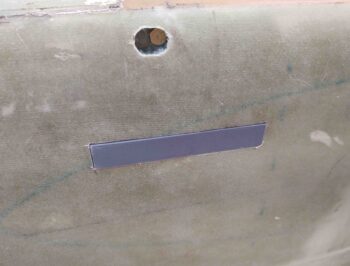
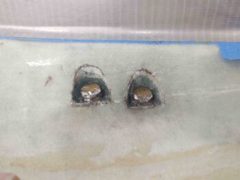
17 July 2018 — (Build Note) I curved the outer edges and tops of the last round of foam additions I made for the 2 aft canopy latch hard points on the left side canopy frame. The forward of these 2 hard points was already at the exact width I needed, 1.85″ while the aft hard point needed a little narrowing so I sanded it down to 1.85″ width as well.
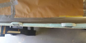
I then laid up 2 plies of BID on the forward hardpoint of this pair, canopy latch #3 of 4.
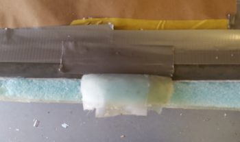
And then also laid up 2 plies of BID on the aft canopy latch hardpoint.
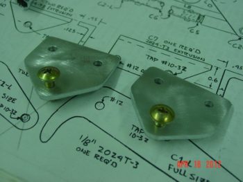
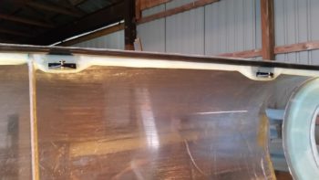
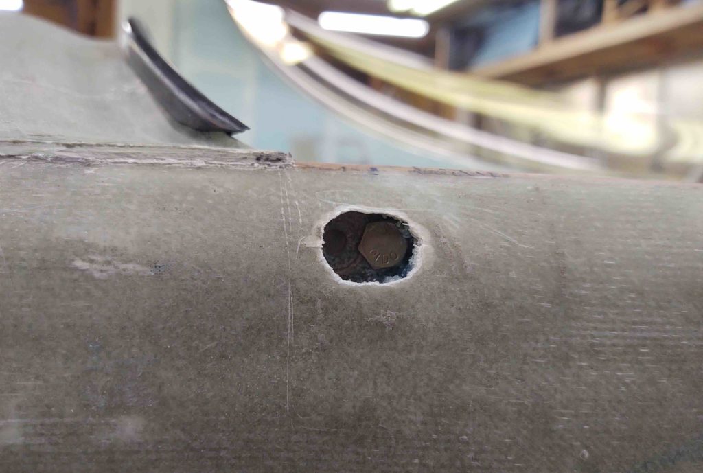
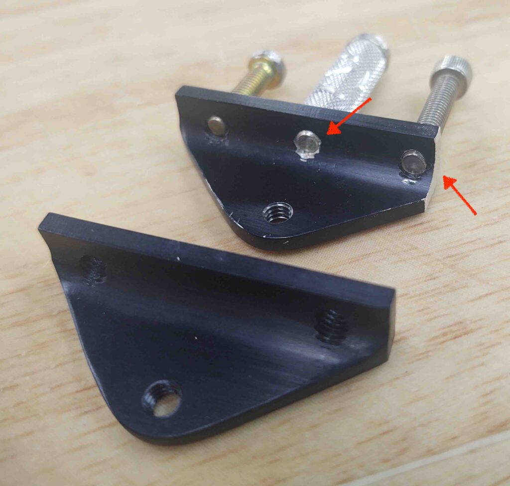
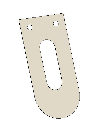
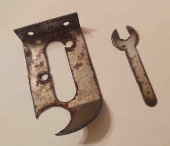
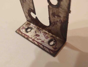
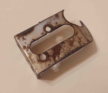
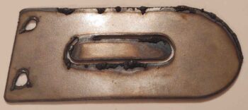
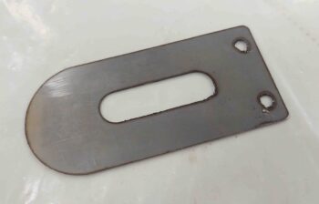
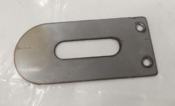
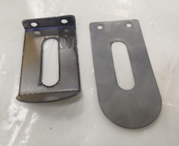
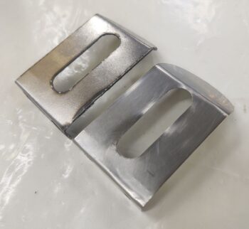
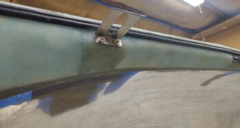
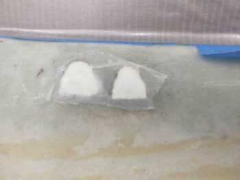
I would like to note that these 2 aft protruding canopy latch hard points (above) are 1 of 2 options that I have for mounting the canopy latch hardware. As per plans, the standard canopy latches will get mounted with bolts running vertically. However, if I find these hardpoints too obtrusive, unsightly or the plans method of latch catch installation too problematic, I reserve the right to shave these off and mount new latches (which I would have to cut out of flat aluminum, see pic below left) which would mount with the hardware installed horizontally (pic below right).
Option #2 is a blatant copy of Mike Beasley’s outstanding work that he did on his canopy, which is pretty close in size & shape to mine (from what I can tell pic wise). I nabbed these pics off Mike’s very informative Long-EZ build site.
One final point of note on my 2 canopy latch options is A) for option #1 I already have all but one set of latch hardware in hand, and B) since these hard points traverse the width of the canopy frame, it’s clearly much easier to lop off the protruding hardpoint section to go with option #2 than it would be to add it later if I wanted to go with option #1.

•••
14 February 2019 — As has been evident many times before in this build, there is often layer upon layer of interdependencies that drive design changes (aka “mods”). This very point became evident after I received my GNS-480 —and after I placed it in just about the only place it could go in my panel— when I realized that my EZ Rotary Canopy Latch from Jack Wilhelmson was just not going to fit. And believe me, for the price I paid and the beauty and quality of Jack’s latch, it was not something I chucked aside in a momentary flight of fancy for something else!
At the time I remembered that both Bill Allen and Mike Bowden had rather unusual canopy latches, somewhat similar in style and appearance, and both of which I had seen at the Rough River fly-ins.
Well, through Alaska Long-EZ builder, Brian Ashton, I was linked up with Mike Bowden… who graciously gave me a very thorough run-down of the dimensions on his canopy latch. These conversations took place almost a year ago.
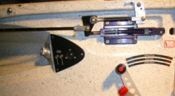
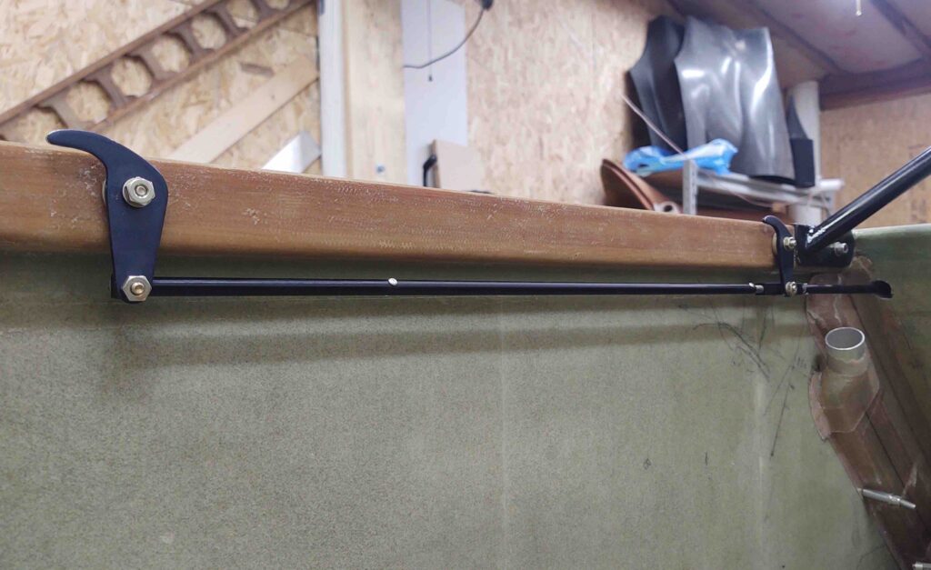
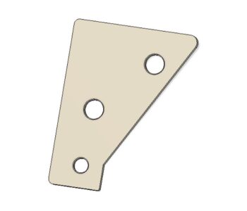
Well, today I finally got around to plugging in all the known dimensions and extrapolating a few of the others to draw up Mike’s canopy latch in CAD. The one significant mod I made is that I added a triangular pivot plate to the canopy latch arm which will allow a forward reaching pivot arm to manipulate the forward canopy hook. If you’ve seen Mike’s Long-EZ than you know he has no need for one of these since he has a permanently attached windscreen portion on his canopy (like an F-104 Starfighter).
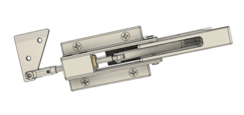
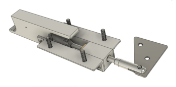
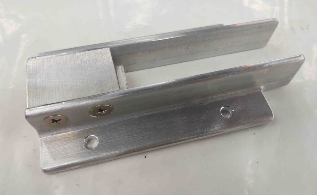
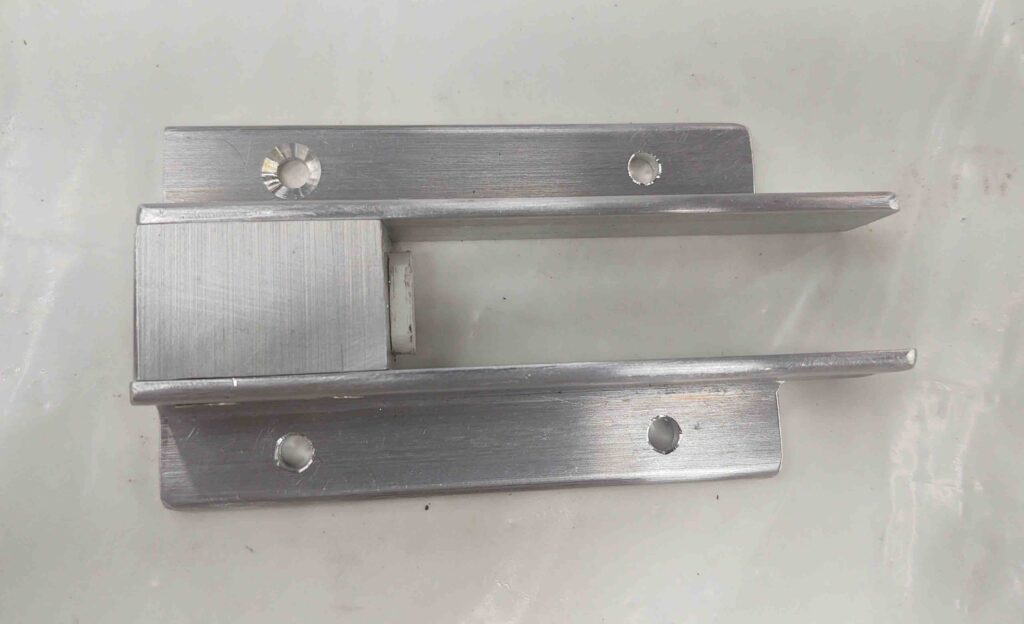
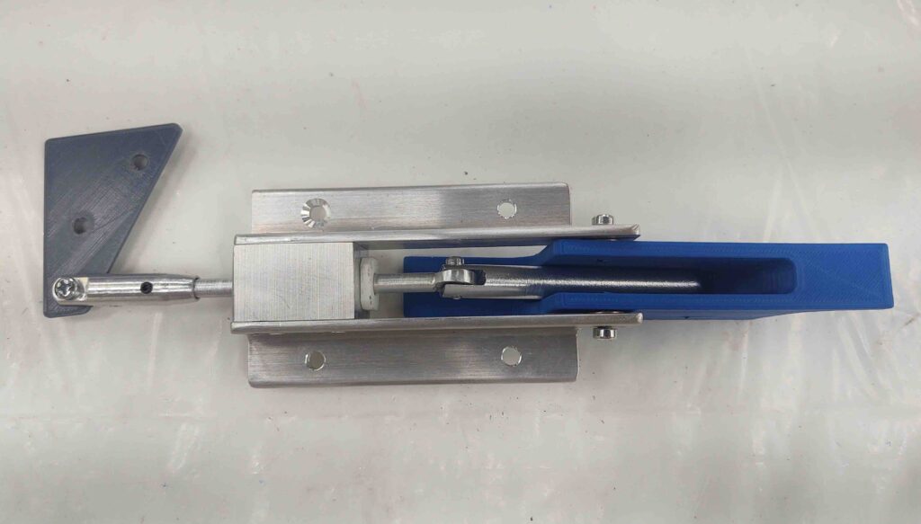
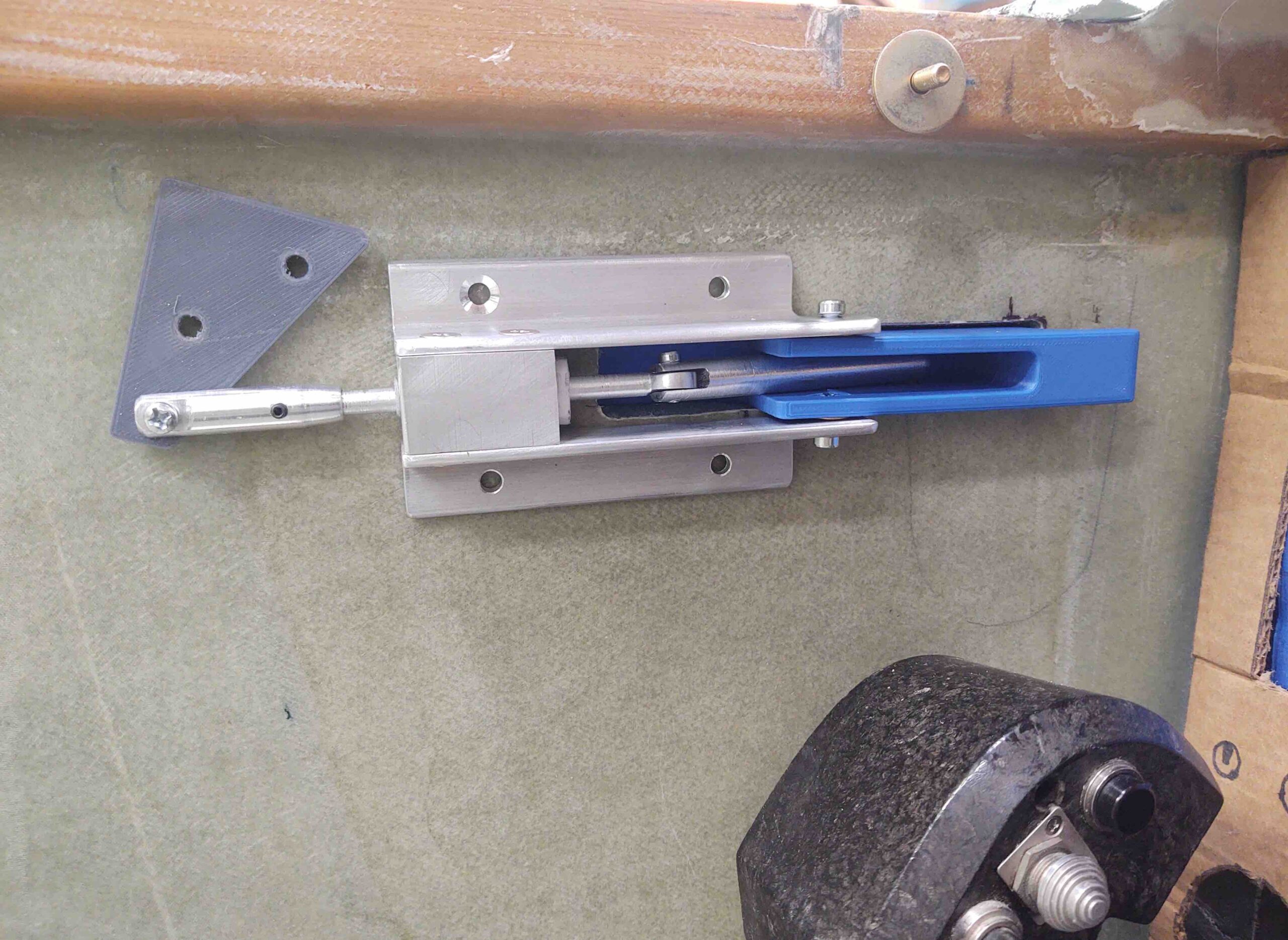
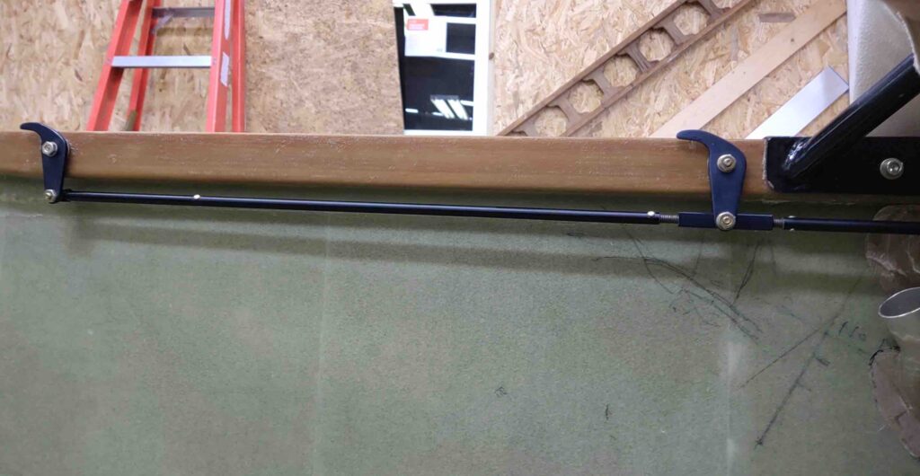
The shot above is a somewhat straight-on view of what you’d see in the cockpit. The one below would be an upward view of the latch from the pilot seat area.
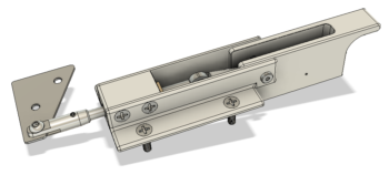
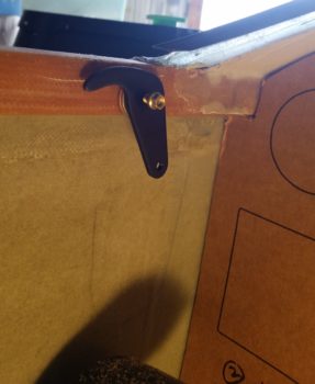
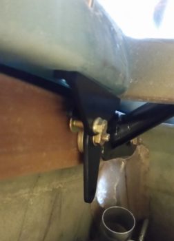
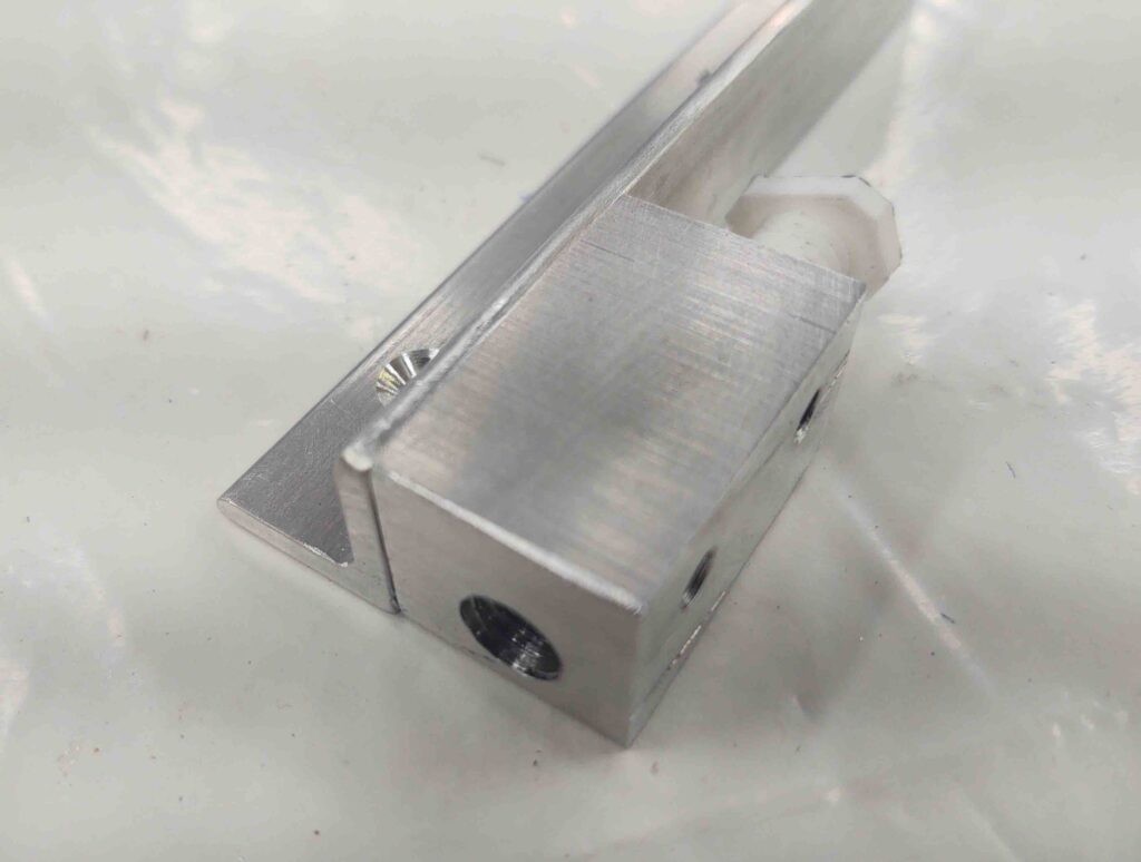
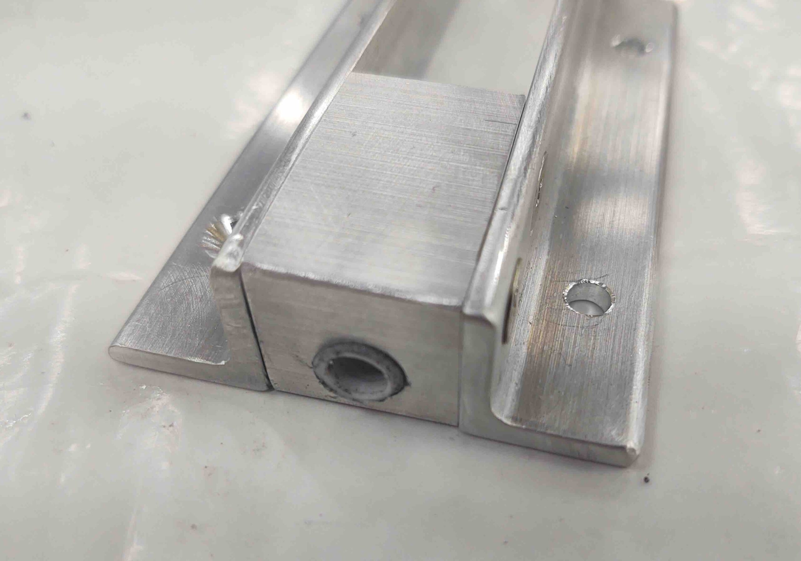
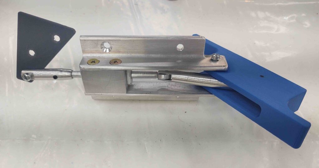
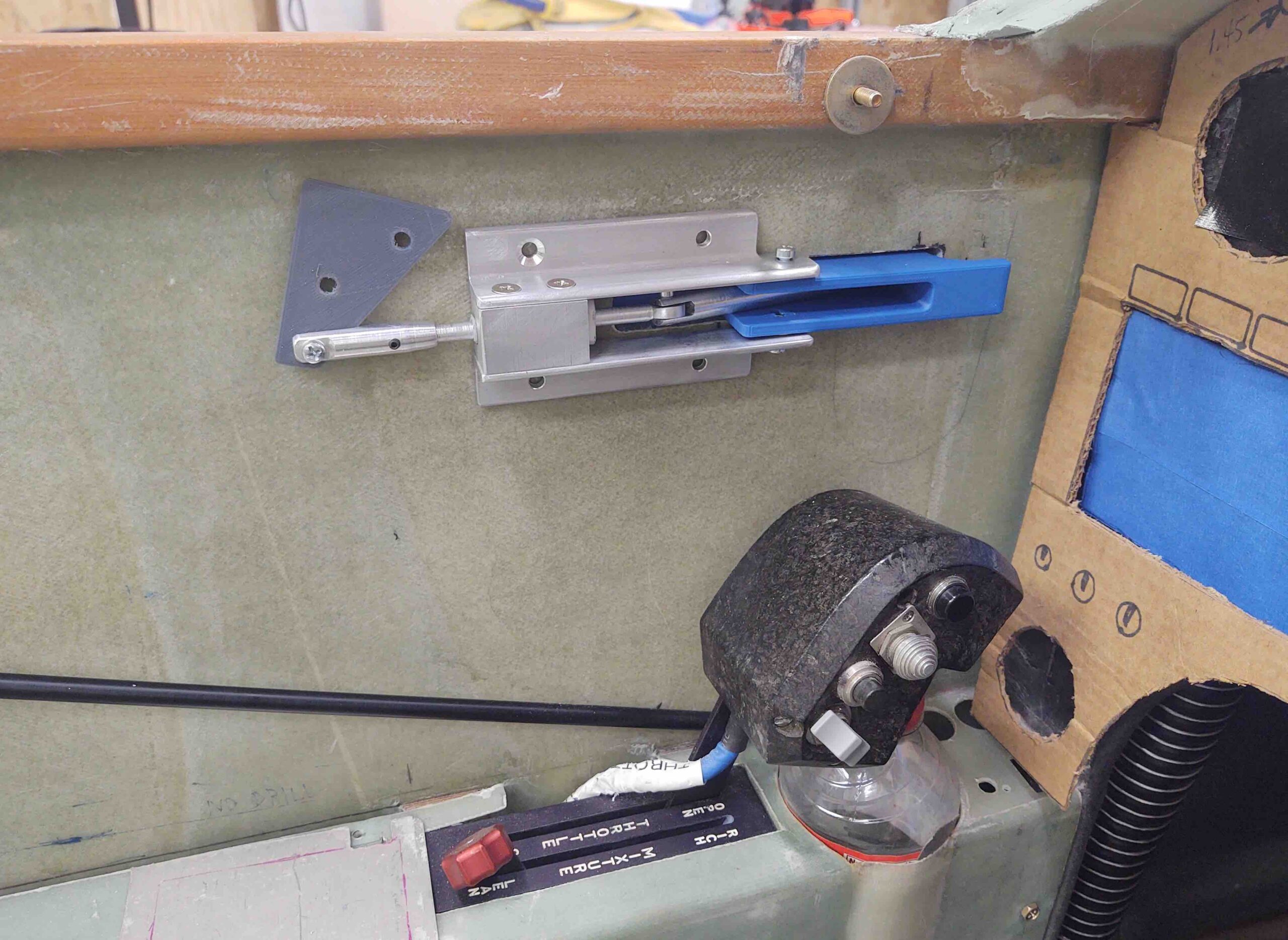
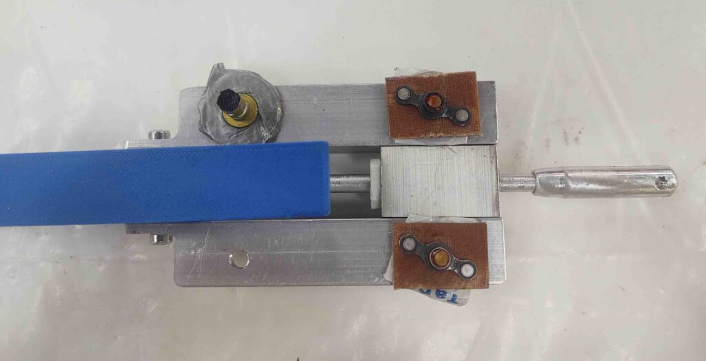
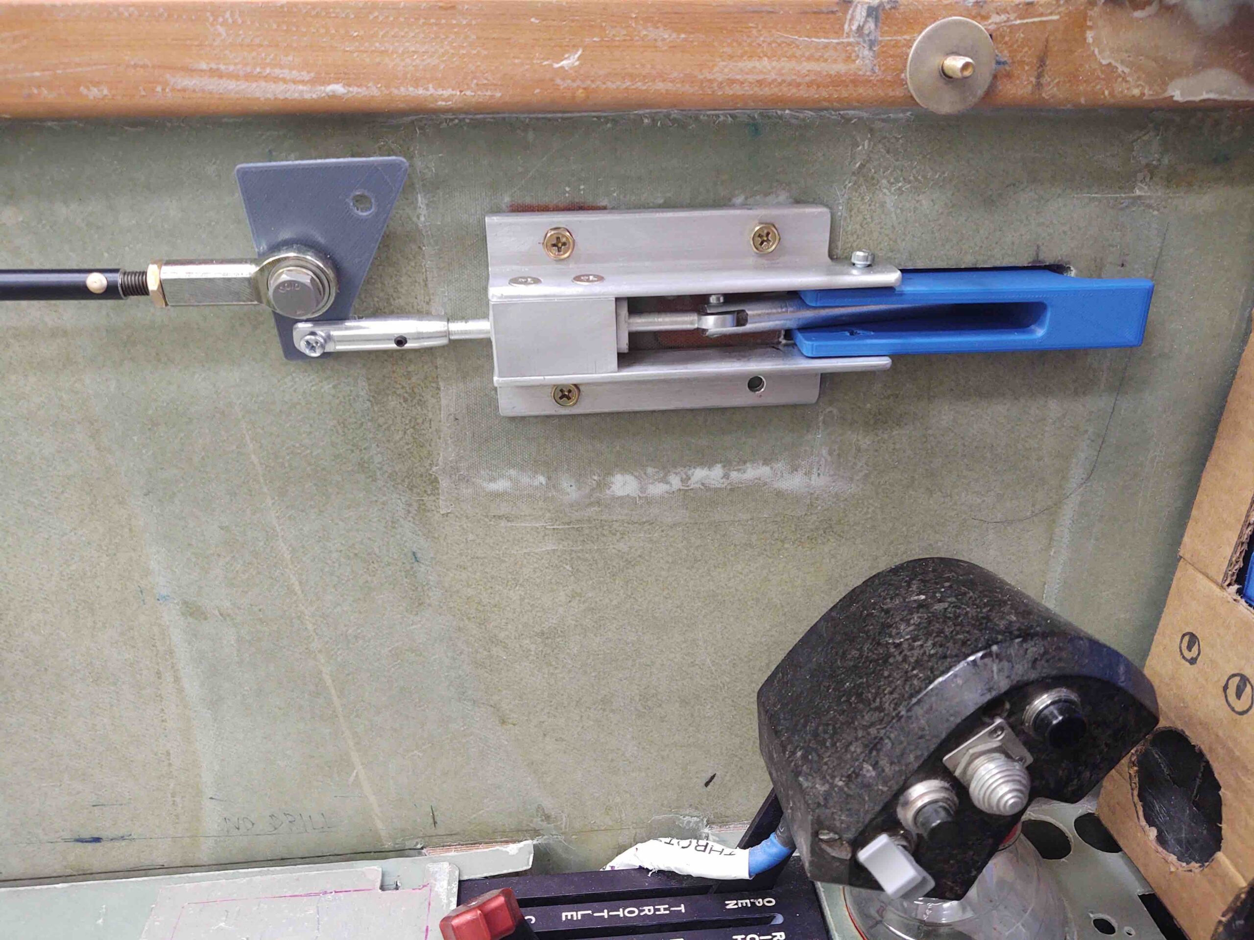
This is an outboard view of the canopy latch, shown with the 4 mounting screws that will secure it in place on the fuselage sidewall.
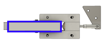
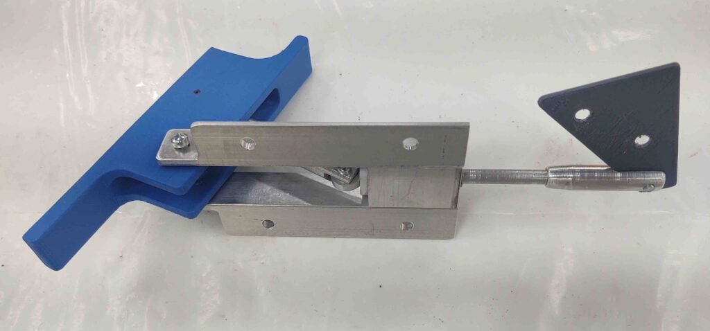
Here’s another outboard view, but here I’ve highlighted (blue rectangle) the exterior handle part of the canopy latch that will be visible from outside the aircraft.
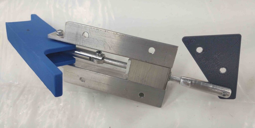
And a snazzed up version of the canopy latch. As I’ve mentioned over the past few weeks, I plan to machine the majority of these CAD-drawn components using CNC once I get down to North Carolina and settled in. That being said, I should also note that I’ve been quite sick this week, so I’ve been doing some CAD work to pass the time (when I haven’t been passed out!).
•••
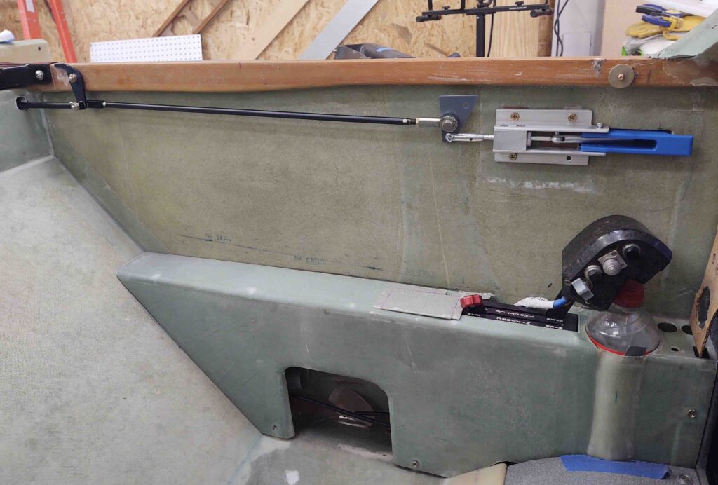
17 February 2019 — Today I was able to create a virtual left-side cockpit space in CAD to get a good feel on the mounting location for my canopy latch. By adding in a bit of the upper longeron, front panel and left armrest, I was able to just about pinpoint the dimensional specs for installing the canopy latch.
In short, this canopy latch will work as planned to provide me the clearance I need with both the throttle handle and the instrument panel (specifically the GNS-480 GPS).
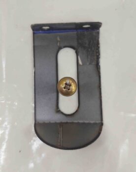
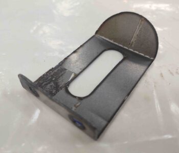
With a per-plans-spec sized sidewall now in my “possession,” I was able to do a fair number of machinations to also figure out installing a lock for the canopy handle. Clearly this is, in turn, a lock for the fuselage proper.
I started with a ‘standard’ sized lock but quickly found they were a bit too robust so I went with the “mini” version (1/4″ less in diameter), which seemed to both fit and look better.
Although in rough format, this pic provides an idea of how the external side of the canopy latch handle will look . . . along with the lock.

•••
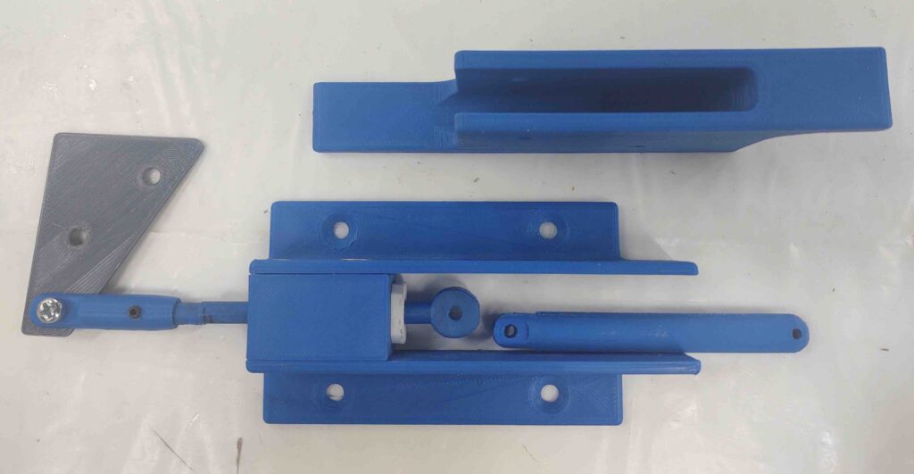
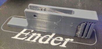
28 March 2019 — I figured as I went about my duties today I would have “Bob” (my 3D printer) hard at work printing out the components to my Canopy Latch assembly.
As I worked up the canopy latch handle in CAD, I spent a good deal of time —all in vain I might add— to connect the components together in Fusion 360 using its various software generated joints in an attempt to make a working virtual model of the canopy latch to see how it would operate… and if there were any configuration issues. Alas, all for naught as I found out from a good unnamed friend of mine that in Fusion 360: “Joints are a b*tch!” True that!
In addition to seeing how this thing will work mechanically in the real world, as with most of my components I want to be able to actually test the size, fit and configuration in my real plane on the next trip down to my NC hangar.
To be clear, this is just a working mockup that will facilitate flushing out any bugs (hopefully!) so I can tweak the design if required before machining the final canopy latch assembly out of aluminum and phenolic.
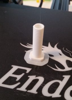
With the white PLA filament still loaded in the printer, I started Bob off printing a mockup of the threaded phenolic sleeve that will thread into the center block of the handle assembly to mitigate friction of the aft sliding connecting rod.
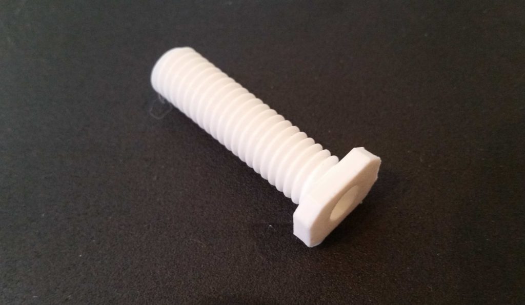
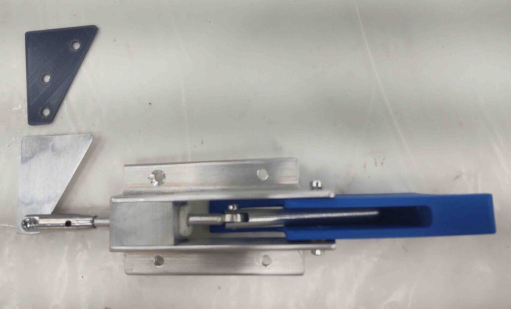
I then swapped the PLA filament to blue and began printing the main canopy latch assembly components. Below is the latch assembly’s lower mounting bracket.
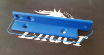
Here we have a “so far” progress pic with the lower mounting bracket and “phenolic” connecting rod sleeve insert.
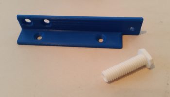
I then 3D printed the upper mounting bracket.

Then came a rather mo-jamma 3D print: mainly since the main handle piece needed supports for the overhanging part of the handle — on the left side in the pics below.
Supports in 3D printing are designed to be removed after the part is completed printing, but serve to support any part that overhangs more than around 45-50°.
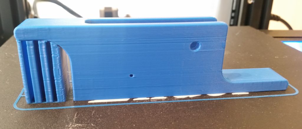
Here’s the canopy latch handle with the 3D-printing supports removed.
And a final glamour shot of the canopy latch handle.
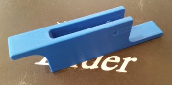
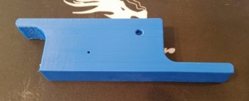
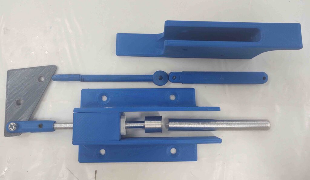
A number of 3D printed parts later (2x connecting rods and connecting end cap) and with no real hardware to speak of, I quasi-assembled the Canopy Latch assembly as best possible. I’m very interested to see how this contraption will work once I get some hardware and attach all the parts together!
I had ordered some black PETG filament from Amazon that had not yet arrived, so I picked up some gray PETG from a nearby Micro Center store.
PETG is a filament that combines the ease of printing of the very common PLA filament with the robust strength and heat tolerances of ABS. Actually, PETG is stronger than ABS but just a bit less tolerant of high heat (PETG is stable up to around 80°C). Moreover, with just a few slight parameter tweaks, PETG prints out somewhat normally analogous to PLA, whereas the much more finicky ABS requires an enclosure around the printer to ensure heat retention during the entire printing cycle of the ABS part. Whereas ABS prints are renowned for their nuisance seam splitting and corner lift-ups off the printing bed, PETG can be excessively stringy and have globules all over the part if the print parameters aren’t dialed in correctly.
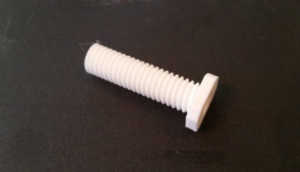
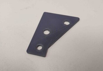
Thus, armed with this knowledge in hand, I set off to 3D print my first PETG part: the small pivot plate for my Canopy Latch assembly (this pivot plate allows the latch to mechanically manipulate the #1 canopy latch hook that physically sets farther forward in the cabin than the canopy latch handle assembly does).
•••
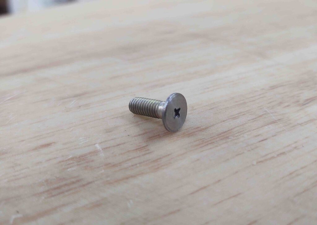
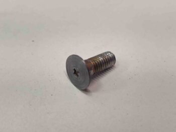
29 March 2019 — Today I ran down to my local Village Hardware Store to pickup the required hardware to make my canopy latch assembly work. There were still some compromises since I couldn’t find any CS screws shorter than 1/2″ (plus, the countersinks on this latch assembly are set for 100° aircraft screws vs. the standard 82° sold everywhere else).
Besides getting a real sense of its size, the best part of having this physical model of the canopy latch assembly is to actually make it function as designed… to see how all the parts move and work together real world. I have to say, so far I don’t see any binding or snags with the configuration so far.
Of course, how this carries over with actual manipulation of the canopy rods and latch hooks remains to be seen, but so far we’re off to a good start.
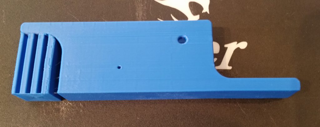
Here’s the outboard side of the canopy latch assembly. You can see where the main body will get bolted –via 4x AN3 bolts– to the interior fuselage sidewall. Also, you can see the rectangular portion of the handle (center/left) that will protrude through the aircraft sidewall and will be visible on the exterior of the airplane.
Since the 3D aspects and functioning of the canopy latch assembly is hard to depict simply by mere words and pics alone, I made a quick video to help describe it…. along with some other 3D printed parts that I’ve made for (or related to) the Long-EZ build.
Here’s a shot of the major 3D printed Long-EZ related components or models that I’m currently working on.
•••
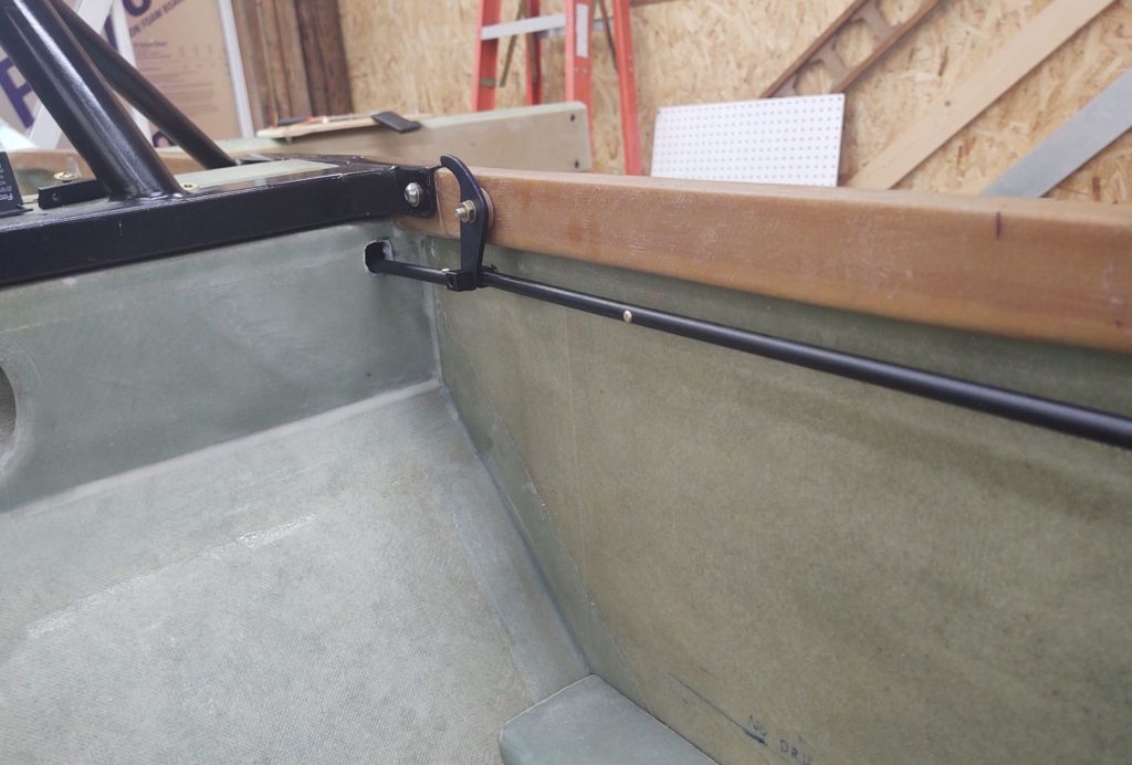
7 June 2019 — Today I finally got back on the build a bit by determining where my canopy latch hooks (C2-Ls) will get mounted to the left longeron.
I started by determining the alignment of the canopy latch hook attach points on the canopy side, then marked the associated C2-L AN3 bolt positions on the longeron.
After marking the canopy latch hook attach point locations at the respective Fuselage Stations, I then measured the required 0.6″ down from the top of the longeron at each canopy latch hook attach point and marked a crossline to identify the spot to drill.
I then drilled a small pilot hole at each canopy latch hook attach point location from the interior outboard and then drilled each pilot hole out further to 3/16″ diameter.
From there, I drilled each hole with a 1/2″ drill bit from the outside in to clear out the foam at each hole and create an opening in the glass skin to allow clearance for the AN3 bolt heads.
Now, you may have noticed that I have 4 canopy latch hooks –2 forward and 2 aft of the pilot’s seat– versus the 3 called for in the plans. The reason behind my using 4 canopy latch hooks is simply to keep my significantly oversized canopy nice and secure during flight. Moreover, my rollbar longeron mount messes with the original plan’s location of the middle canopy latch hook and required me to move it forward to avoid the rollbar mount. This left quite a gap between the middle and aft canopy latch hook assemblies, so I added a fourth canopy latch immediately aft of the rollbar mount.
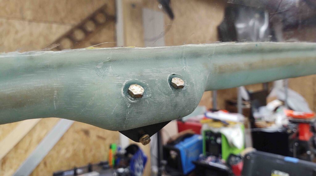
Below are the aft 2 canopy latch hook attach points with the AN3-13A bolts and 2 each AN970-3 washers in place. Since my longeron is about 0.3″ thicker from the front seat aft, I’ll need to increase the length of the aft bolts a bit longer than the current AN3-13As.
And here we have the forward 2 canopy latch hook attach points with the AN3-13A bolts and 2 each AN970-3 washers in place.
Finally, here’s a shot of the very forward canopy latch hook in place at the plan’s position, F.S. 44. Of course, this canopy latch hook is definitely not per plans either since I’m using a very different canopy latch handle than the stock version.
•••
10 June 2019 — Today I again focused mainly on the canopy latches to get them as far along as possible on this NC trip.
I started off by gathering up all the actual C2-L latch hooks, thin washers and standard nuts (to allow for removing the C2-L assemblies when it comes time to paint the longeron) and installing them onto the left longeron.
Here we have the front set of C2-Ls…
And below is a shot of the aft pair of C2-L latch hooks in place. As I mentioned in my last post, I had to swap out the AN3-13A bolts for AN3-15As for the aft two C2-L latch hooks since my longerons are about 0.3″ thicker from the front seat aft. With the bolt swap out the aft C2-L latch hooks, washers and nuts fit spot-on.
With all the C2-Ls in place I then measured the distance between all the latch hooks to determine the required lengths of the connecting tube segments that will link all the C2-L latch hooks together to be actuated simultaneously by the canopy latch handle.
I also took the opportunity to inventory all the parts I have on hand in an attempt to ensure that I have what I need to connect up the canopy latch system… unfortunately I don’t and will have to acquire/make a few parts.
NOTE: Remember my canopy latch setup is a bit different than the stock configuration.
I then got busy assembling the 4 canopy-side C8 latch catches.
•••
11 June 2019 — I started off today in a failed attempt to follow the plans in using Bondo (aka “Builders Bog”) to set the C8 latch plates in place on the canopy hard points. I don’t know if the Bondo was too old or if the C8 surfaces were too smooth and shiny for bonding, but being in transition meant I had no Acetone or accessible mineral spirits to clean up the C8 edges for bonding.
Wanting to get these canopy tasks moving forward, I simply crawled into the cockpit and set the C8s in place one-by-one as I marked where they needed to be attached with a finer-tipped Sharpie. I then held up the C8 to its respective outline, adjusted for the Sharpie line width and then marked the holes for drilling.
I will point out that my C8 install is unlike the plans steps where you Bondo the undrilled C8s to the canopy hard points, then drill through both the attached C8 and canopy hard point in one step, to later then drill out and tap the C8 mounting holes. My install is different since I’m using Jack Wilhelmson’s Canopy Latch Kit which included predrilled and pre-tapped C8 latch pieces.
To ensure my alignment both in drilling the C8 mounting holes correctly spaced and C8 alignment in relationship to the C2-L latch hook –including proper clearance with the longeron– I started each C8 install by drilling one hole, setting the C8 in its proposed spot, climbing into the cockpit to check clearances & alignments, then remarking before drilling the second and final hole.
The C8 mounting placement on the #2 canopy hard point (just forward of roll bar frame) sits just under the actual embedded canopy edge, which leaves me no option to place the mounting screws either on the inside of the frame as I did with the aft two C8 latch plates (#3 & #4) below, nor on the external side of the canopy frame as I did with the very front latch plate (#1) . . . [Sorry, no pics this time of the exterior holes on #1].
I’m not surprised on the improvised method I’ll need to employ for C8 latch plate #2 install, since incorporating mods on an already-modified pseudo-French canopy install is going to call for some unique, out-of-the-box processes to complete.
The #2 C8 latch plate will thus get mounted by pre-mounting threaded pins to the C8 mounting holes and then floxing those pins and the C8 into place inside 2 holes drilled into the canopy hardpoint, much as we do on many other components of the build (elevator hinge plates, baggage pods, etc).
I have to say that I’m very happy with how the canopy hard points worked out for the aft pair of C8 latch plates spacing and configuration-wise.
My improvised method worked fairly well with only a couple minor SNAFUs.
First, with no proper drill bits on hand I stopped off at Harbor Freight and picked up a cheap set of bits. I mean, after all, I’m only drilling through fiberglass and foam. I have to say this was the worst purchase I’ve made at Harbor Freight, having used numerous drill bits from there before. I broke 2-3 drill bits literally within the first few minutes, and unfortunately one of these was in the forward hole on the #3 canopy latch hardpoint.
As frustrating as it is, I’ll have to punt on this #3 C8 install (below) and drill the broken bit out later with a good quality drill bit . . .
In addition, somewhat analogous to the countersunk screws required to attach the canopy frame to the canopy hinges… and my not having the correct lengths on hand when I needed them, so too did I not have all the correct lengths of button head screws required to install the C8 latch plates (again, this is not a standard plans canopy install). As you can see below I improvised with some AN bolts/screws I had on hand as I await the menagerie of button head screws to arrive from ACS.
Beyond some minor logistical and qualitative tool challenges, getting these C8 latch plates’ mounting locations nugged out was a big step. As with most things on this build, doing the initial install in any given area begins the iterative process of flushing out all the further required steps in acquiring correct parts, redos/repairs and prerequisite data collection for subsequent tasks.
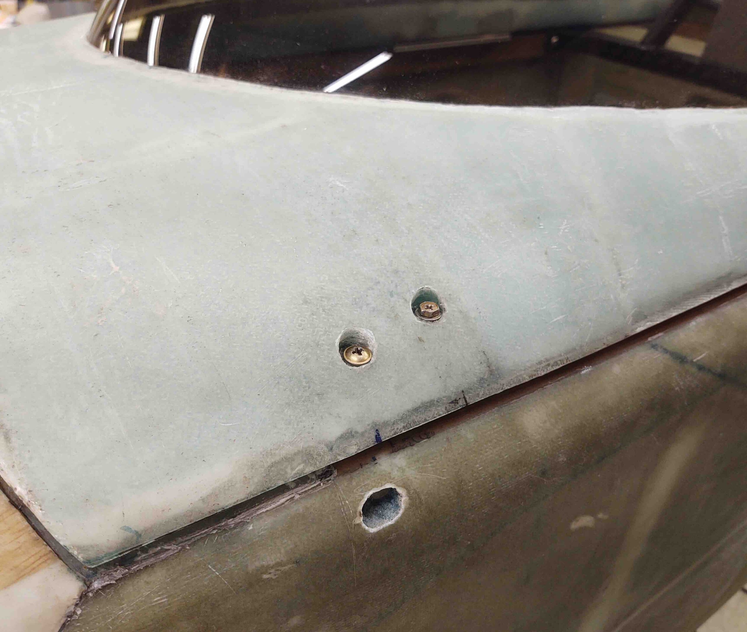
Here we have the aft pair of canopy C8 latch plates in place.
And here’s a shot of the #1, #3 and #4 canopy C8 latch plates in place.
•••
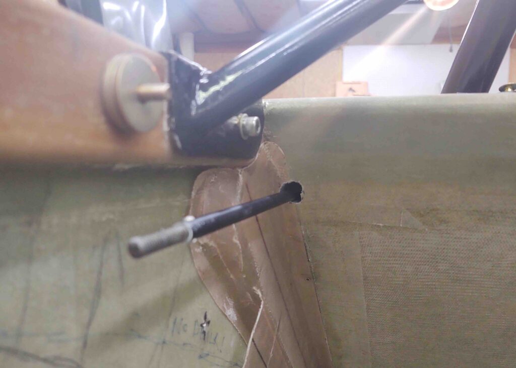
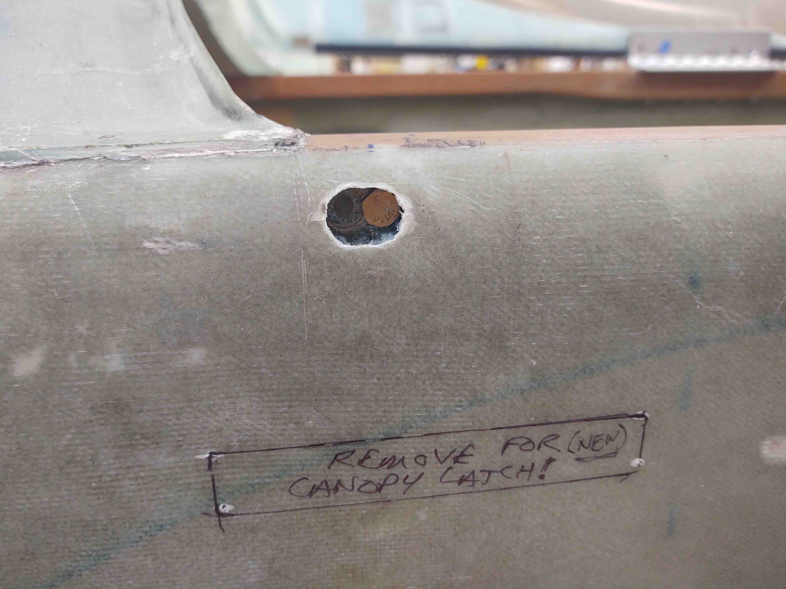
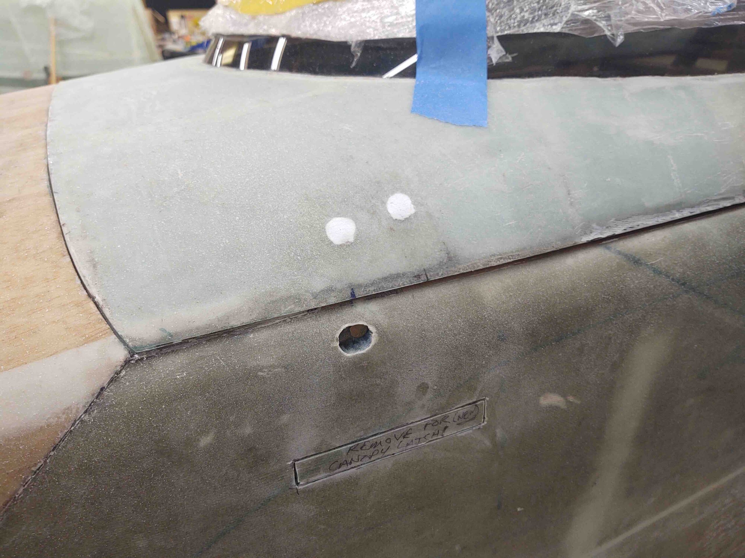
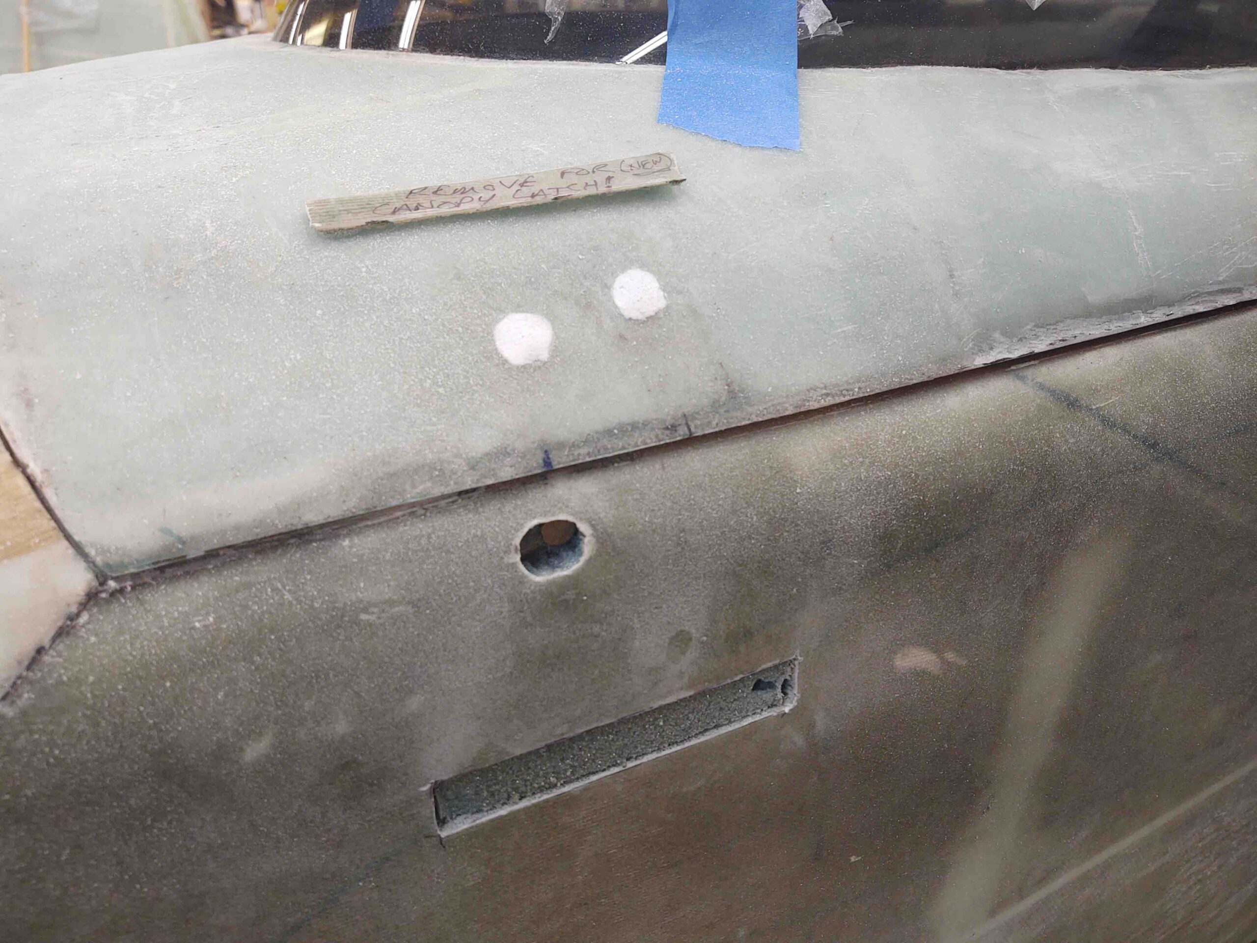
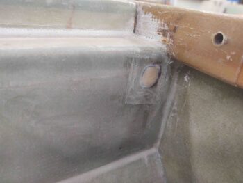
25 August 2020 — The other day I used some left over flox to fill in the current front canopy latch hook bolt hole.
Well, today I moved the hole by checking it on the upper latch and then drilling a new hole about 0.2″ aft of the original one.
Of course I had to widen the exterior hole in the glass and foam to get the new bolt installed.
•••
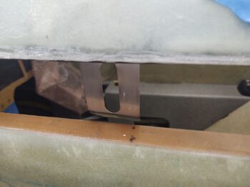
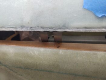
29 August 2020 — The canopy tasks in this posts are from over the past few days… I’ve been doing a ton of measuring, mocking up, testing, tweaking, etc. to dial in the canopy latch system.
First off, to fine tune the positions of the longeron-mounted canopy hooks (C2-L), it made it much easier to move them in unison. Besides the fact that I needed to punch a hole through the upper pilot seatback for the interconnecting canopy latch rod at some point anyway.
After determining and marking the rod through-hole position, as best possible, on both the front side of the pilot seatback…
And the aft side, I then got to drilling.
And was then able to finally connect the back set of latch hooks to the front. Remember, since my canopy is massive, combined with needing to move my center latch hook forward to avoid the roll bar frame, I added another latch hook assembly just aft of the roll bar to make 4 total (vs 3 stock).
A point of note: As I posted on before, I bought Jack Wilhelmson’s canopy latch handle kit with all the required canopy latch parts included. Then my buddy Marco bought a baggy of miscellaneous canopy hardware components at the Rough River auction a couple of years ago. Since he’s been focused on some sweet upgrades to his flying Long-EZ, JT, he gave me the bag to cherry pick some of the parts. I’ve used the bare minimum parts to add the extra latch hook assembly, and some rod pieces… it really helped a ton having those extra bits on hand. Thanks Bro! But not to be outdone in Long-EZ buddy cool points, I’m giving him my Jack Wilhelmson canopy latch for his project bird… it’s a nicely machined latch, but as I’ve pointed out I just can’t use it in my configuration.
Also note that due to the curve of my fuselage + the width of the heating/cooling intake air duct at the aft sidewall/seatback corner, I actually need a dogleg at the #2 canopy latch hook with the canopy latch rod attaching on both sides of the hook.
Here we have the canopy latch rod through-hole on the aft side of the pilot’s seat .
And a shot from above…
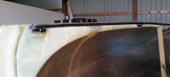
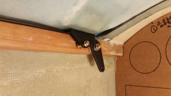
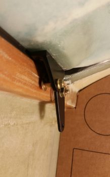
With the canopy rod fairly dialed in through the seatback, and after many iterations of spacing between latch hooks and the canopy side C8 latch catches, I went to work installing the oddball of the 4 canopy-side latch brackets: C8 #2.
You see, the configuration of C8 #2 is different from the others since I have no physical way to install a pair of bolts/screws in the topside of the canopy bracket hardpoint to secure the C8 bracket to the underside rail of the canopy frame. Since my canopy frame is much thinner than standard, at this hardpoint the canopy is literally straight above the C8 canopy latch bracket. Thus, no physical bolt clamping pressure can be used to hold this C8 #2 to the canopy.
What to do?
I decided to flox it in place. Although this C8 bracket could be considered extra, I still want it to be as mounted as securely as possible.
I decided to add a middle hardpoint to the C8 since I’d be relying solely on the power of flox to hold this sucker in place. I drilled and tapped a 10-32 hole, then used an AN3 bolt to mount a Cozy Girrrl baggage pod insert to the new center flox hardpoint. On the aft side I used a stainless steel hex head cap screw, a bit longer since there was a good bit of canopy hardpoint meat to drill into there. On the front side I used a shorter bolt because it was closer to the front edge of the canopy hardpoint.
I then rounded the heads of the bolts to keep the bracket insert holes as narrow in diameter as possible.
I then took a deep breath and proceeded to drill the 3 holes into the bottom of the canopy frame into the #2 latch hardpoint.
I’ll point out that besides the adding the extra/middle hardpoint for the baggage pod insert, I also had to trim the aft side of the C8 bracket to avoid hitting the rollover assembly mounting rail… how’s that for planning?!
Improvise, adapt and overcome . . .
I whipped up some flox, tending towards the wet side, and then floxed the #2 C8 assembly to the bottom side of the canopy. I held it in place with Gorilla duct tape, specifically focusing on pulling the tape more taunt on the bottom side to pull the C8 inboard with whatever scant amount of play (not much) was there.
Well, although I had checked countless times in my C8 vs latch hook alignment, Murphy reared his ugly head and after the C8 was installed —super strong as I wanted it!— I just could not get the C8-mounted button head screw AND the latch hook to fit between the inboard frame of the C8 bracket and the longeron. Something seemed to have changed in the spacing/alignment in the mounting process.
Something had to give. Either I try the heat flox and remove C8 floxed inserts method, or try thinking outside the box. I seriously did not want to apply a bunch of heat to the bottom of the canopy frame… so I decided to trim down the thickness of the button head screw head.
So I chucked up the screw in the lathe.
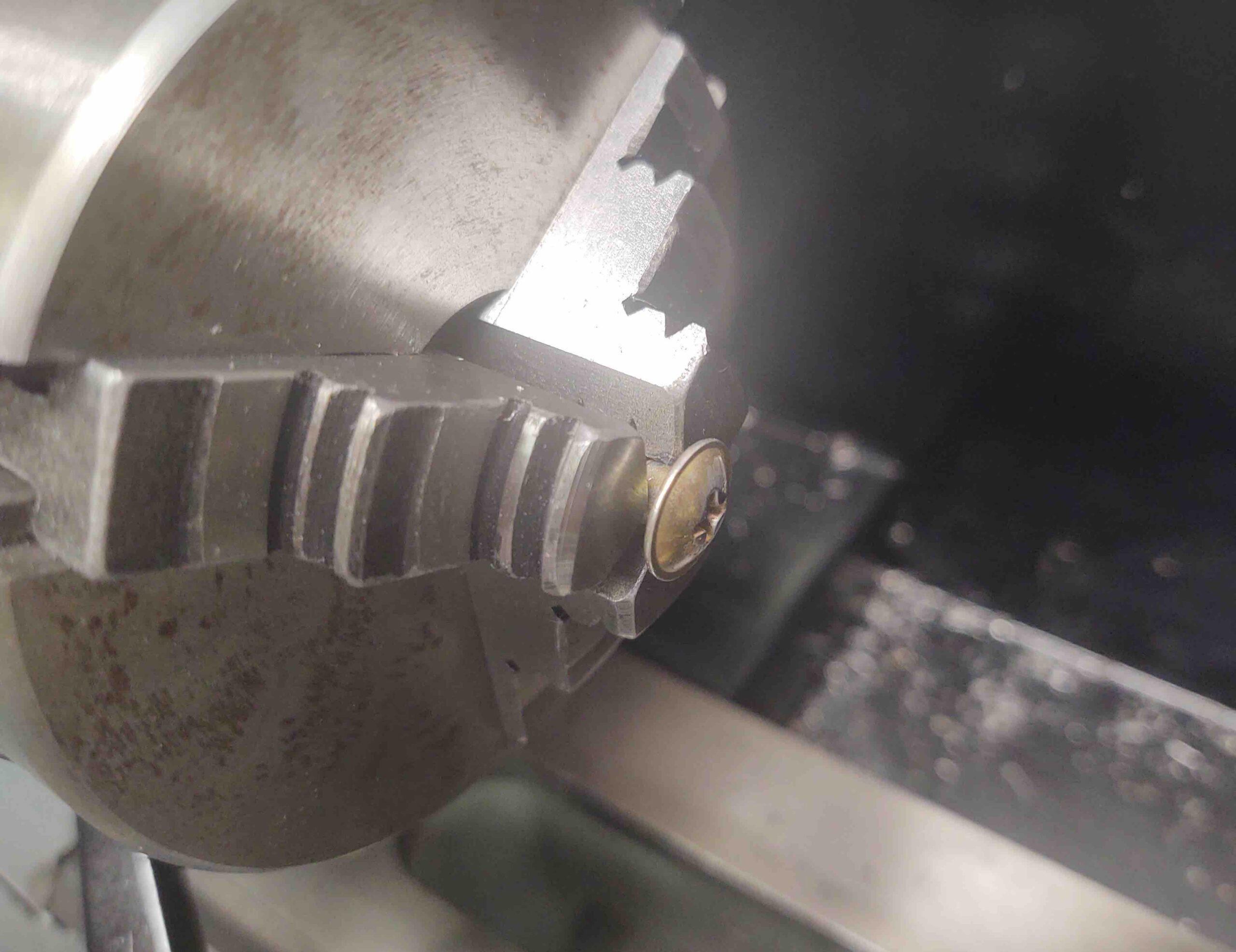
And narrowed the diameter of the head while also greatly reducing its height.
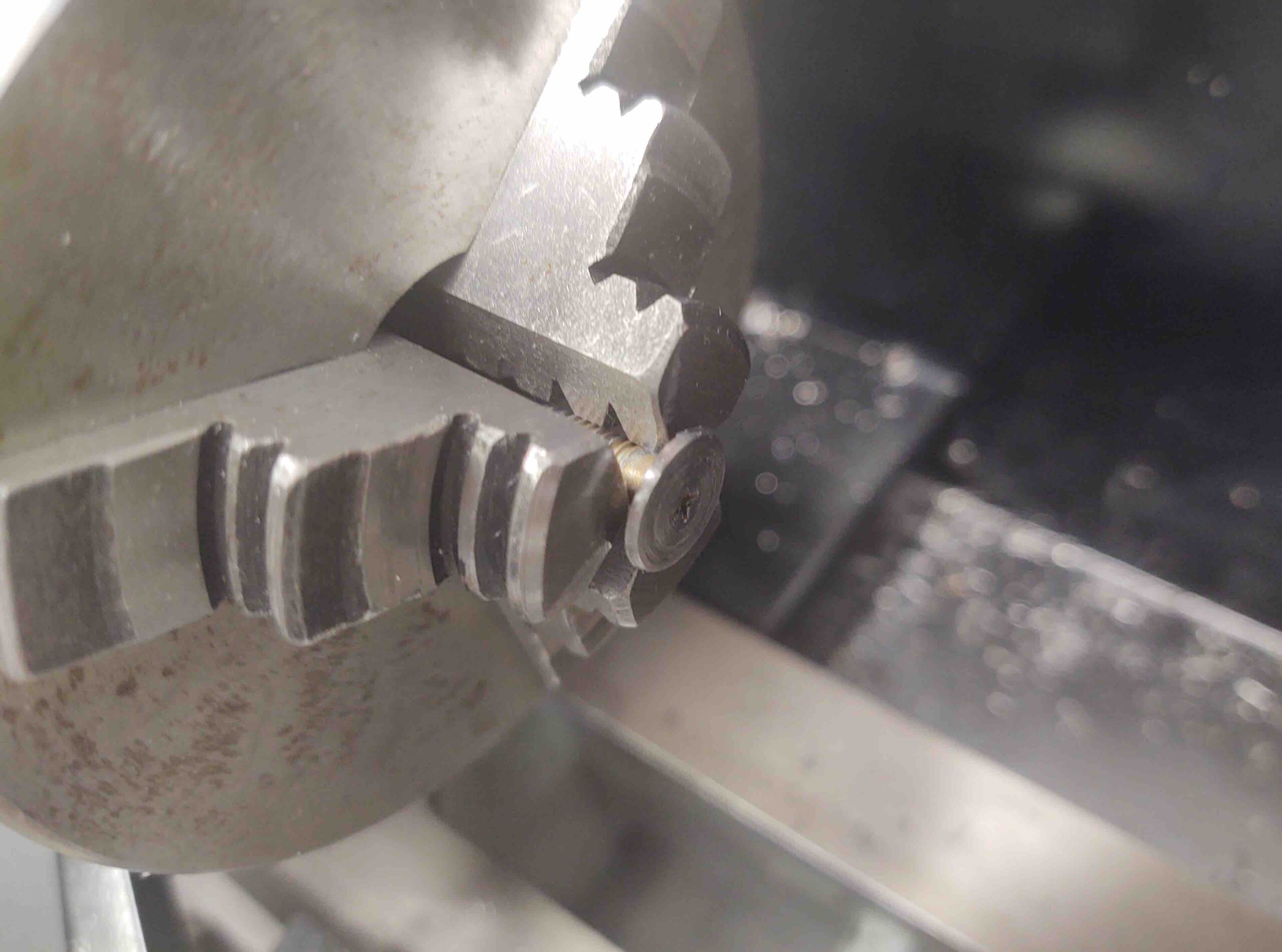
The new (and improved?) C8 canopy bracket hook latch bolt.
I did also do a fair little bit of sanding on the longeron and was able to dial in the barest minimum of clearance to get the canopy closed without the C8 nub scraping the longeron, while also getting the hook to seat on the screw shank freely.
I then turned my sights to the very aft canopy latch hardpoint: #4. I had this C8 bracket installed, but did need wider diameter notches on the top to allow for using AN3 bolts vs the narrower head NAS bolts I had installed originally.
I climbed inside the GIB seat with my trusty Dremel tool and went to work.
And not too much later had the #4 (all the way aft) C8 latch bracket floxed and bolted to the canopy.
I also knocked out the final mounting of C8 bracket #1.
A couple of years ago when I worked on the canopy at the hangar, I didn’t have any of the correct length of screws on hand since my canopy clearly doesn’t match a stock one.
Well, although I had ordered a plethora of button head screws, I ended up using a button head screw + NAS bolt pair for a couple of reasons: the NAS bolt’s length, with a thin washer, was the perfect length (vs button heads) on the aft hole for not having any thread poking out the bottom side of the C8 bracket.
But just as important: button head screws suck for not stripping out when you really torque them… (I really don’t like them). So what I did was torque down the button head screw all the way, with the NAS bolt threads barely engaged in the threaded C8 hole. Once the button head was good to go, I then used a nut-driving “screw”driver to cinch up the NAS screw nice and tight.
Here we have 3 of the 4 C8 brackets installed on the canopy (#1, #2, and #4). As a reminder, I unfortunately broke a drill bit off deep into one of the holes on C8 bracket #3’s mounting hardpoint. It will take some effort and cunning to get that hole cleared to get a bolt mounted in there, so I decided to get the “easier” C8 brackets installed first.
•••
30 August 2020 — I didn’t get a lot of shop time in today. However, what I did do was very significant and a huge milestone for my Long-EZ build. I finally extricated that darn broken drill bit from the forward bolt hole of the #3 canopy C8 bracket hardpoint.
It took nearly an hour total using the Dremel tool with a very tiny ball cutter bit. Almost what a dentist would use for drilling a cavity. Regardless, I finally got it without too much destruction, other than an oversized hole.
I filled the hole with flox and then went about installing C8 #3 using AN3 bolts.
Of course to first get the proper length bolts I had to sit in the back seat with my Dremel tool and carve away the semi-circular, half-moon notches (both in height and circumference). I also had to allow for getting a wrench and/or socket around the bolt heads to tighten them.
In the end, to get the length just right on the bolts I needed to add a thin washer to each one.
Here’s the final product. Not bad!
With this being an oversized, non-plans, one-off canopy I’m very pleased that the hard points have lined up as required this far.
•••
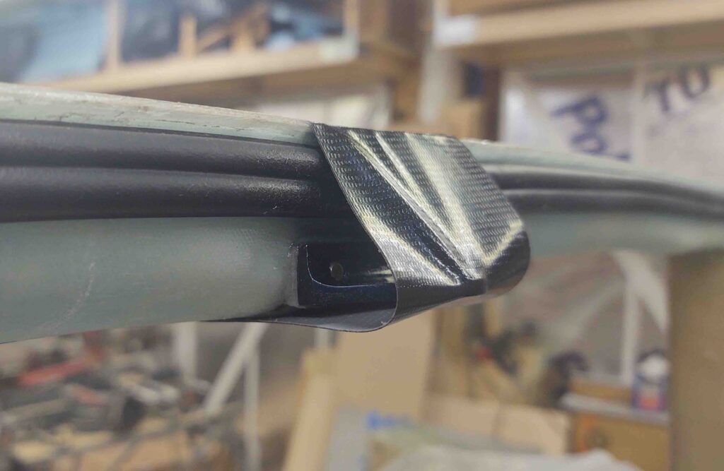
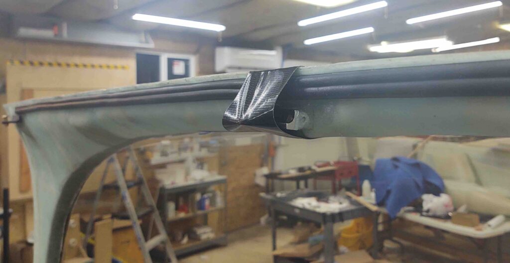
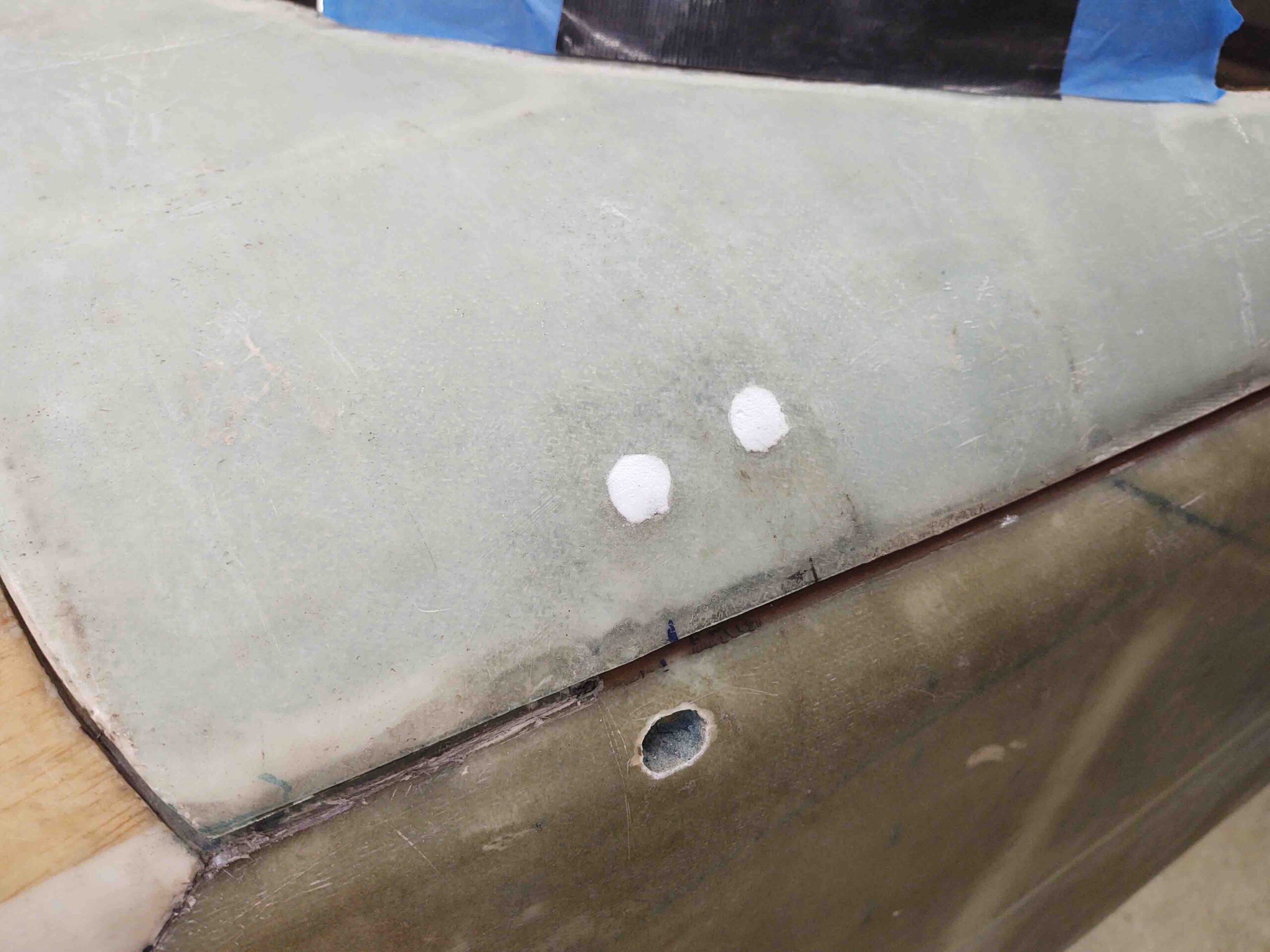
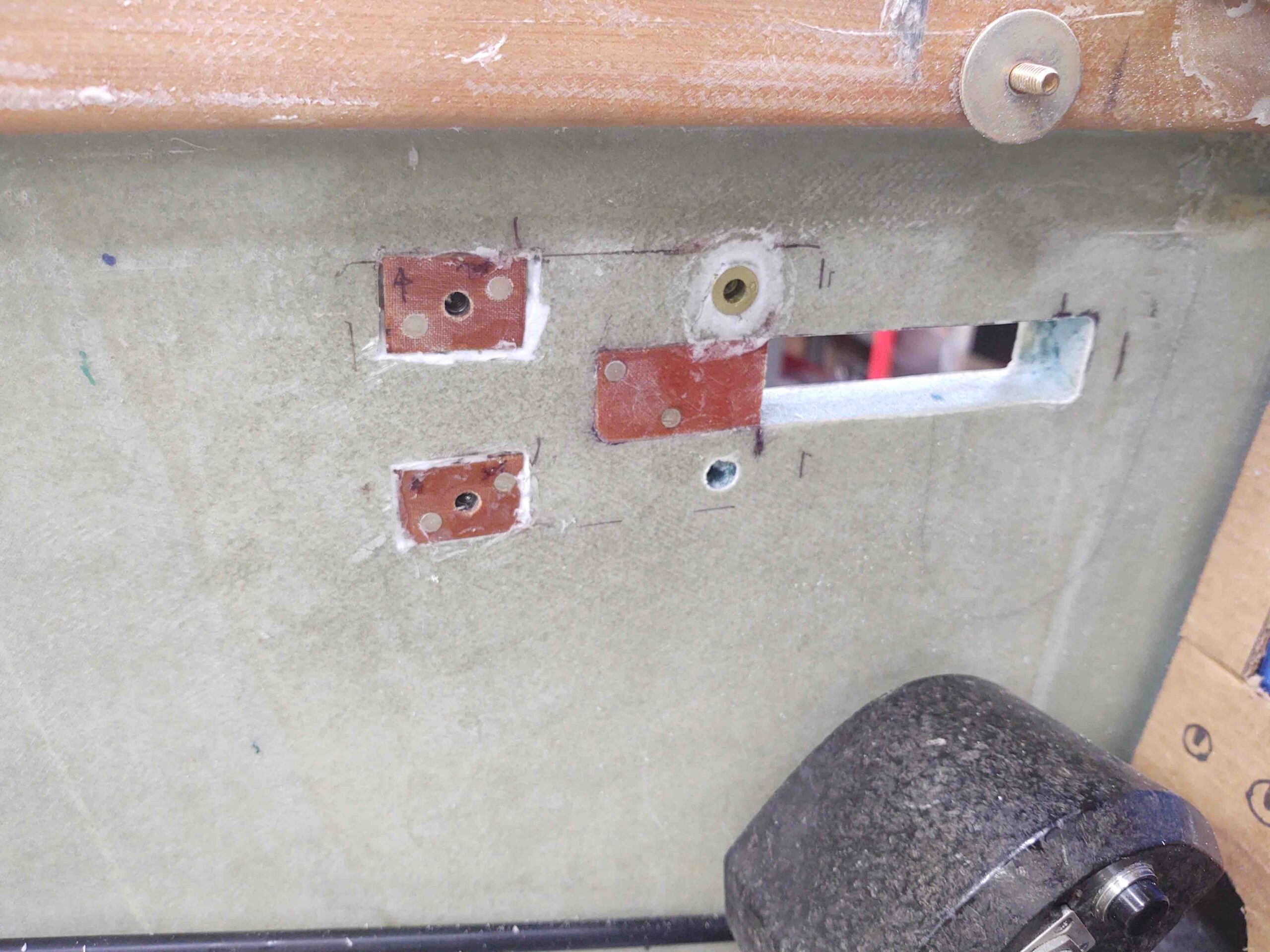
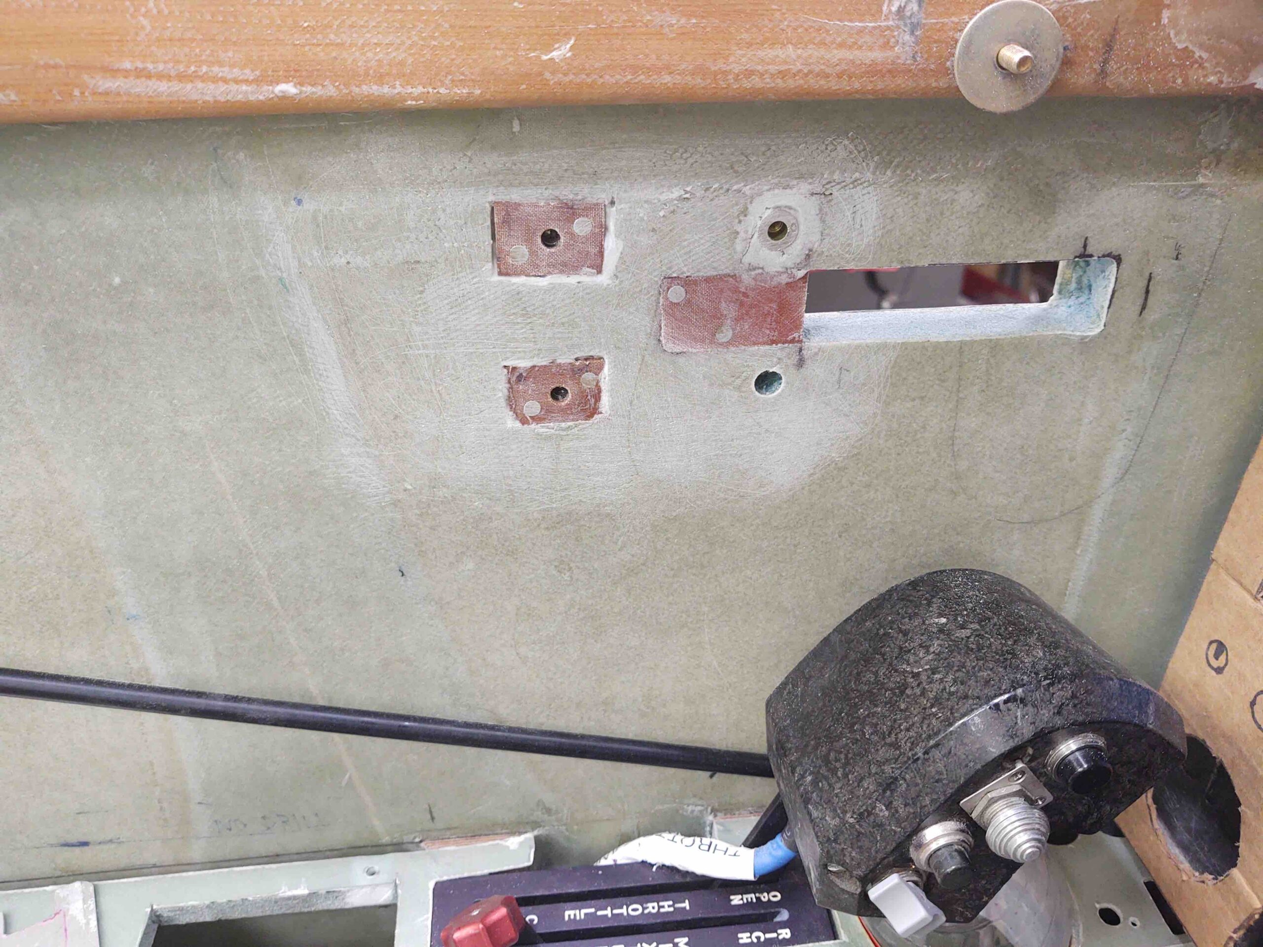
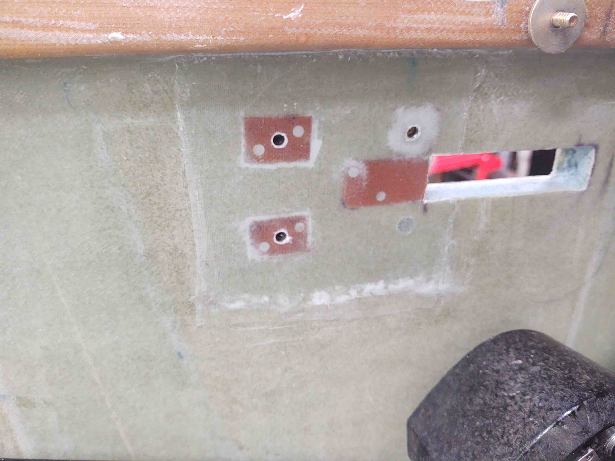
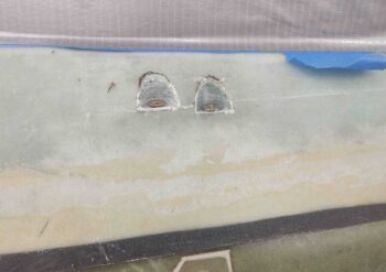
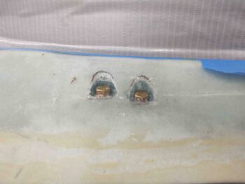
31 August 2020 — I mixed up some dry micro for the canopy’s #1 C8 bracket. This is the only C8 bracket whose screw/bolt heads show on the external surface of the canopy.
I first ground down the screw and bolt heads to ensure they were below the surface of the canopy frame skin.
I then filled the screw/bolt depressions with the dry micro.
 I then messed around with the canopy hardware components for a good hour. Man, my configuration is proving a tighter fit than called for in the plans between the canopy C8 brackets and the longeron mounted C2-L hooks.
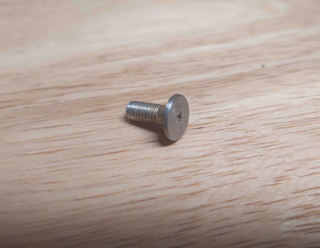
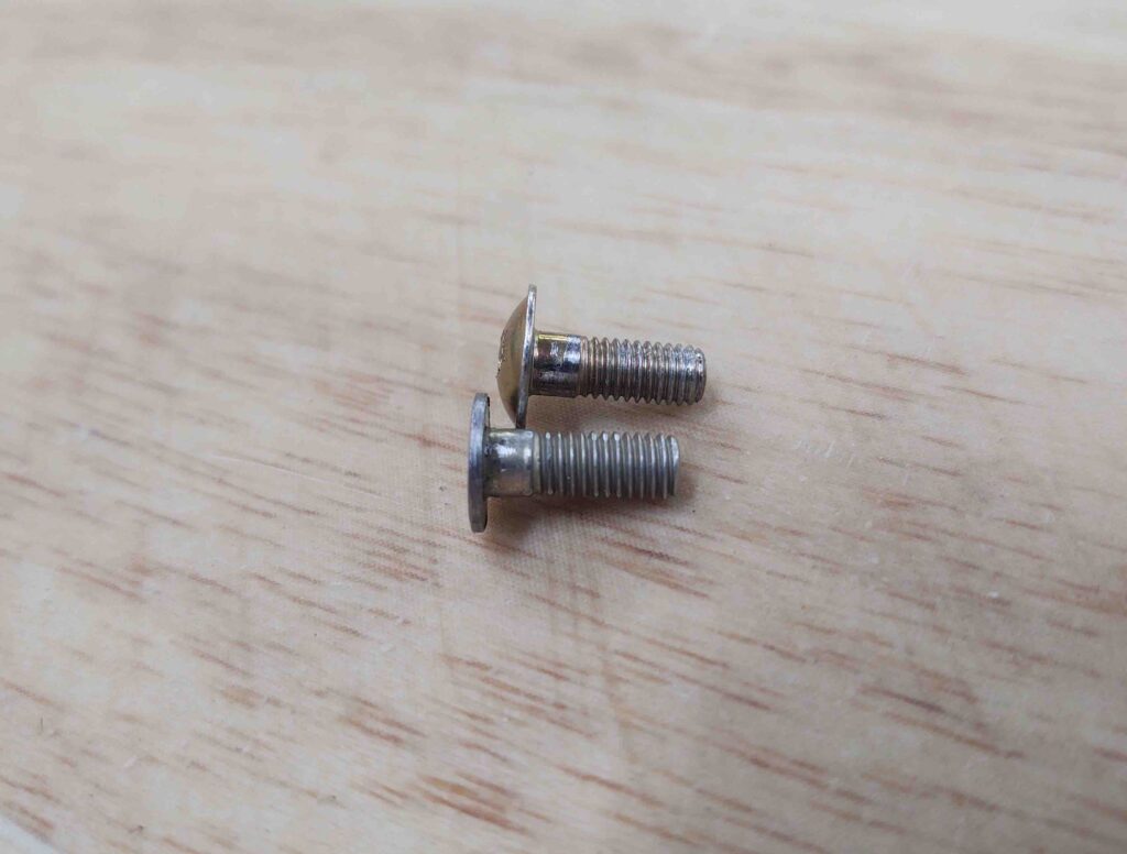
I decided to do some lathe work and simply convert all my button head screws –that mount on the C8 for the retaining part of the latch that the lower hooks catch on– to low profile canopy catches.
Here’s one of the 3 new ones I machined tonight.
And although it might not seem like that big of a difference, the low profile catch screw heads are about 0.035-0.040″ thick. Whereas the original button head is about 0.1″ thick. That means I’m gaining about a 1/16″ (0.063″) in clearance for the hook between the inboard C8 bracket frame and the catch screw head, which can be pushed further outboard towards the inside edge of the longeron.
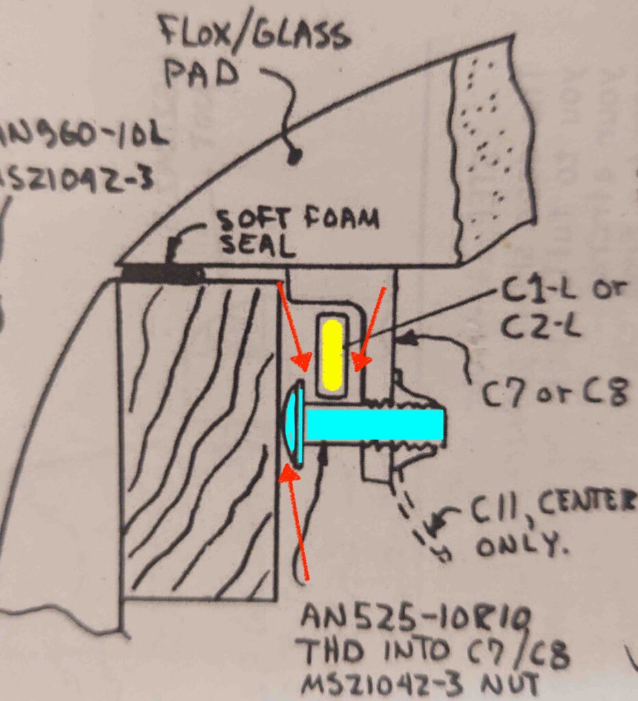
To make what I’m blathering on about here more understandable, I’ve added a shot of the C8 cross section diagram from the plans below. The highlighted light blue screw is what I’m modifying, since it is really the only variable in the equation for squeezing out more clearance at the 3 points depicted by the red arrows. The latch hook (C2-L) is highlighted yellow.
Actually, on canopy hardpoint #2 (just forward of the pilot seat) the clearance was so tight that I sanded a very minor depression into the longeron –without breaking through the glass layers– to squeeze out another maybe 0.020″ to the gap. Clearly I prefer not to have sand a vertical trough into my longeron at each canopy latch point. C8 #2 is the tightest of the 4 canopy latch points, follow by #1 and #3, with #4 being ok.
My last task of the evening was climbing into the back seat for a good half hour and cleaning out tape and dead glass from the canopy and frame junction. Slowly I’m getting the canopy-to-frame edges cleaned up to an acceptable level.
•••
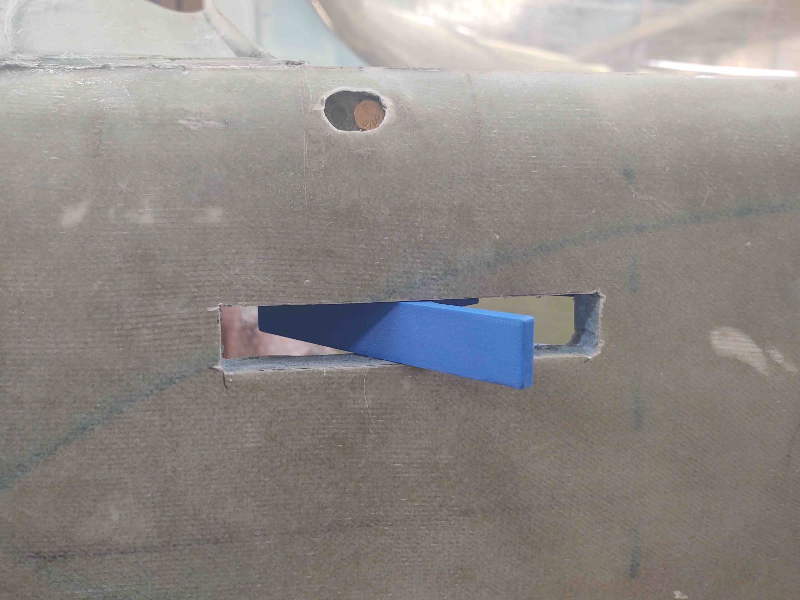
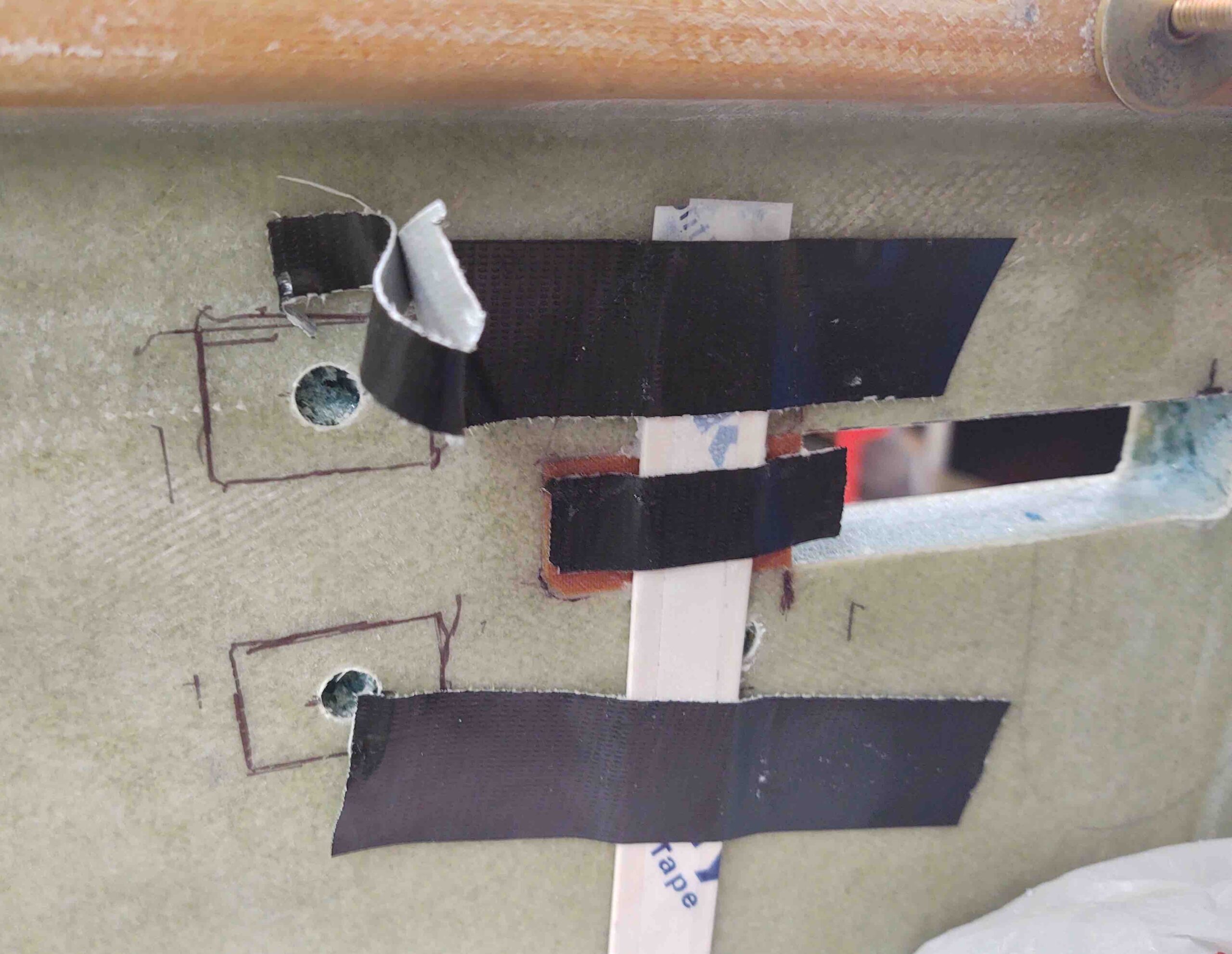
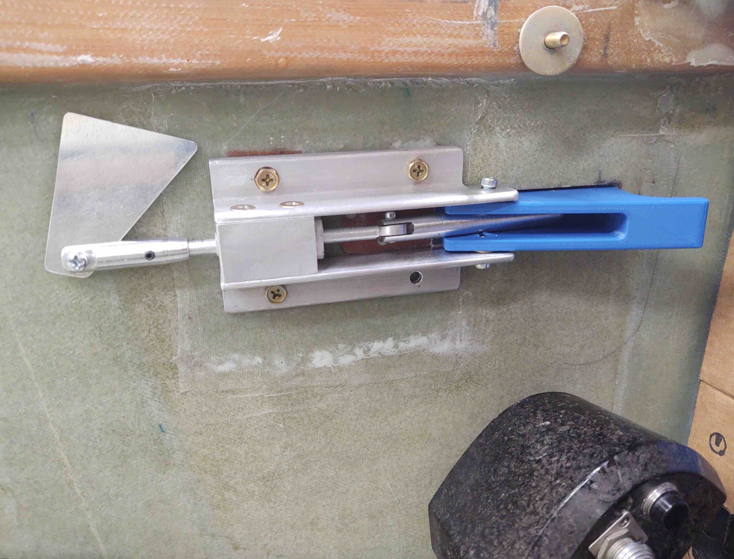
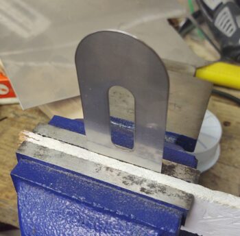
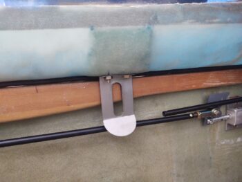
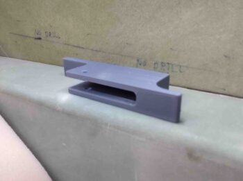
3 September 2020 — Today I got busy working on the canopy latch install. I rounded up my 3D printed canopy latch mockup to use as a template, and then after deciding the final location used it to mark the spot.
Not wanting a ton of fiberglass dust and foam bits inside the cockpit, I drilled 4 small pilot holes as straight as possible through the fuselage sidewalls at the corners of the canopy latch mounting through hole.
I then used my Fein saw to cut the perimeter of the marked latch through hole.
Extricated the piece of outer skin.
And proceeded to dig out all the internal foam.
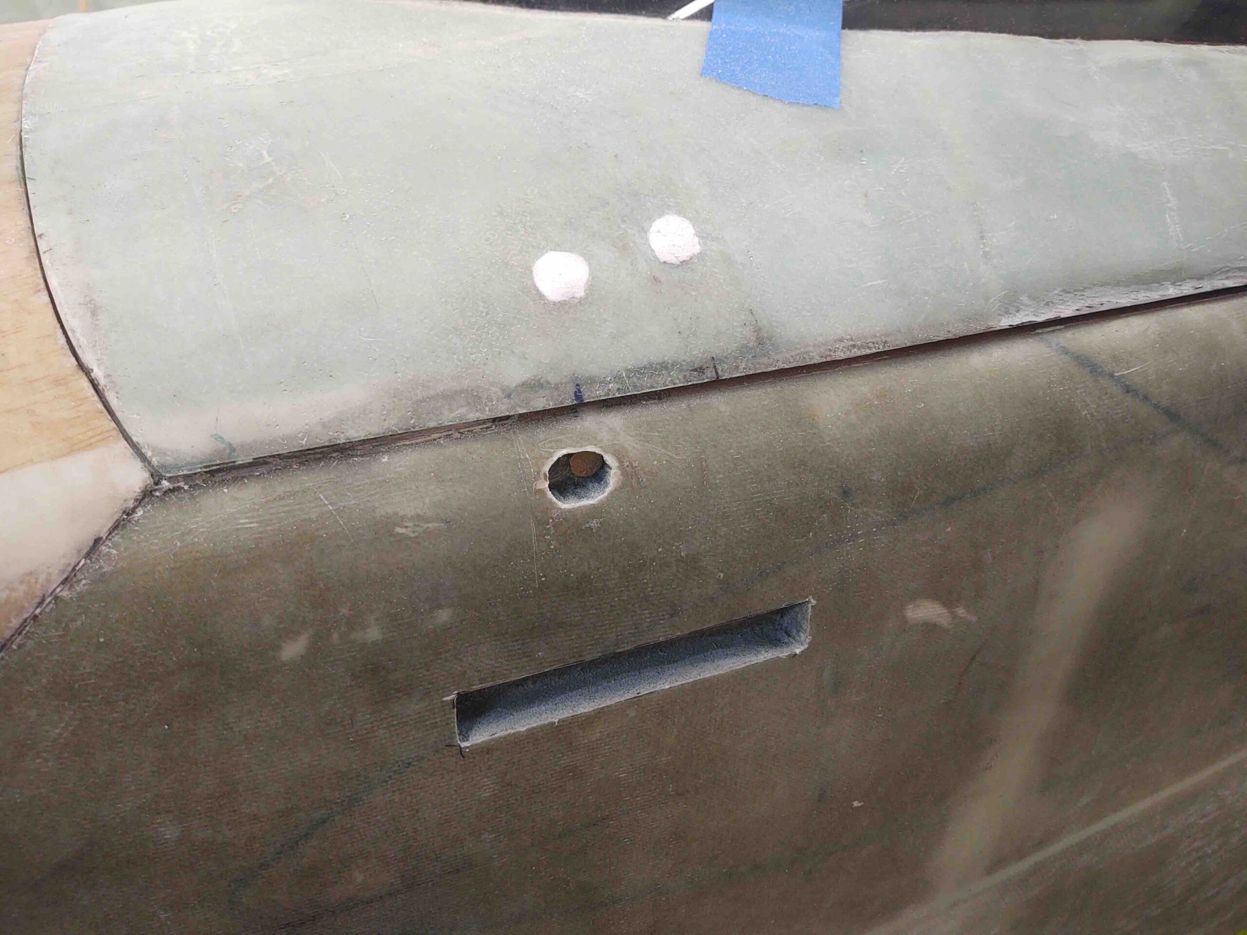
So far so good… here we have the canopy latch through hole with external skin and interior foam gone.
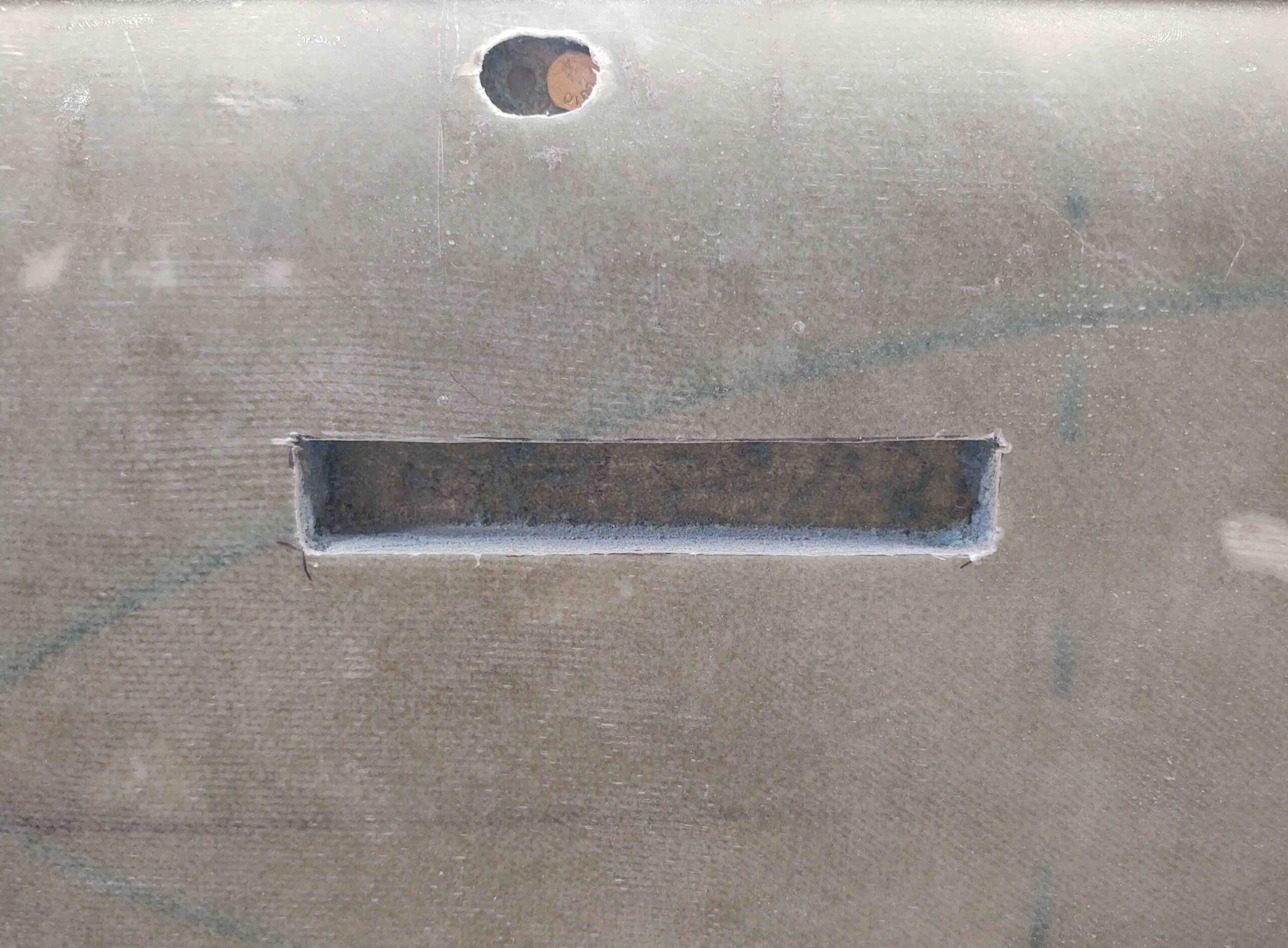
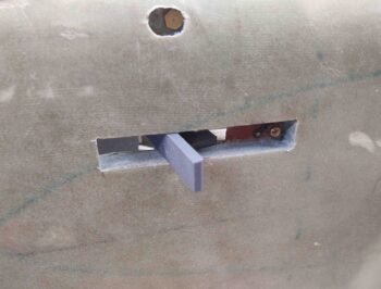
I judiciously sanded around the inside edges of the hole until I was able to fit the canopy latch handle in –the actual part that will reside in the through hole.
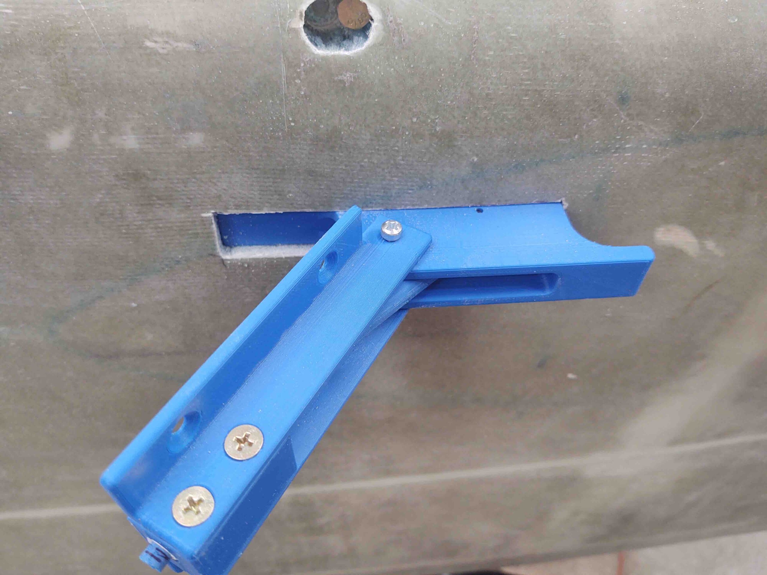
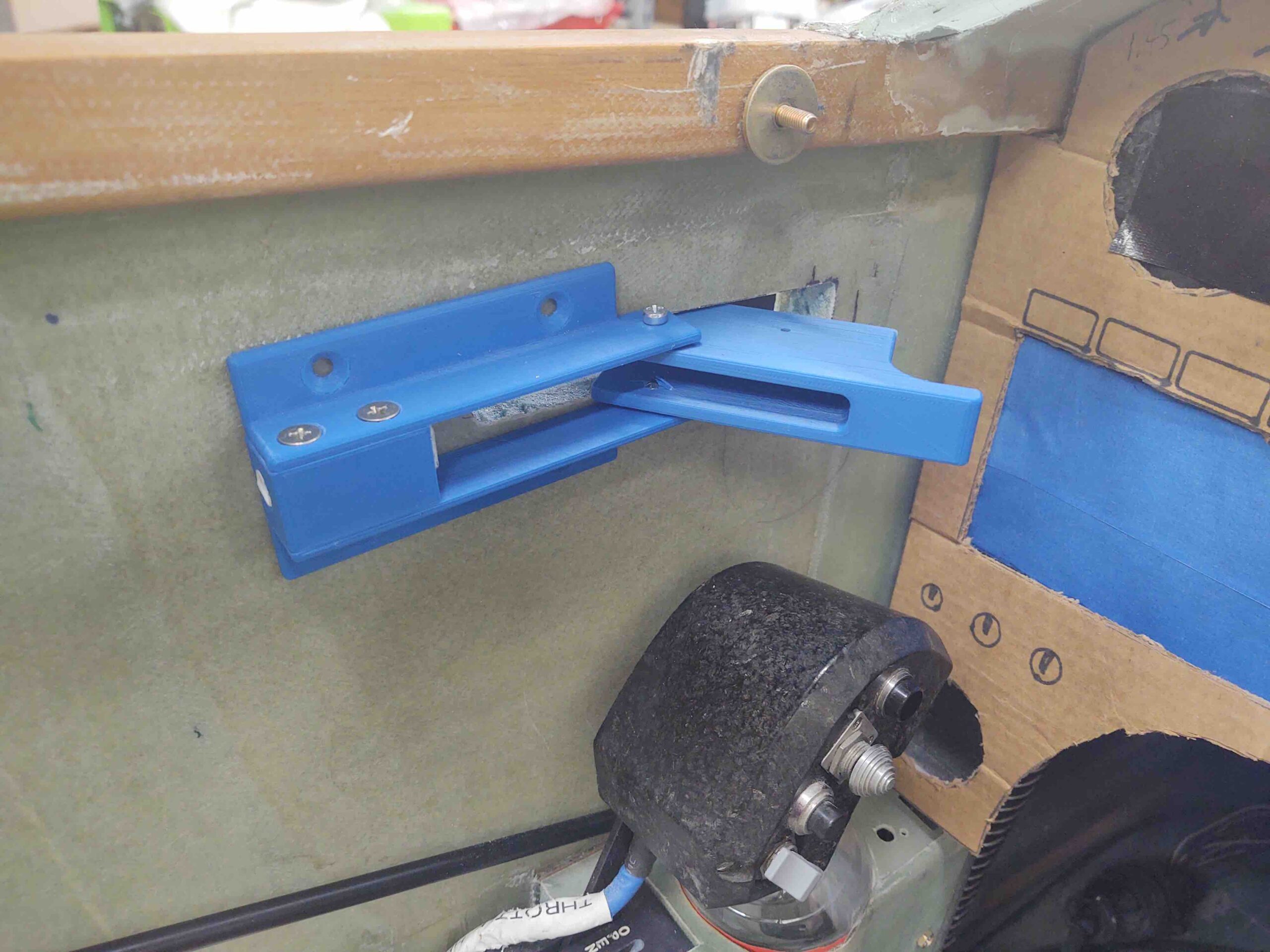
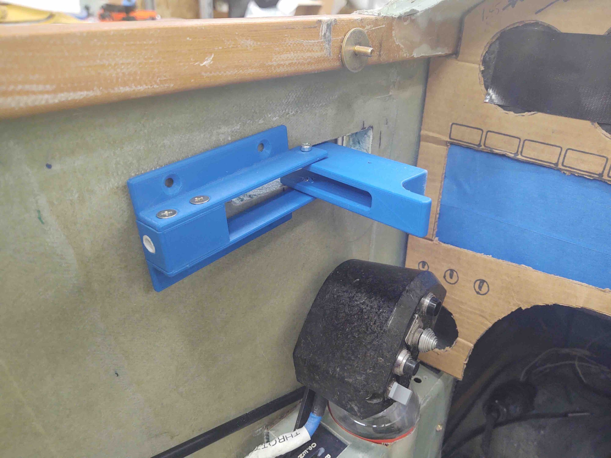
I then cut out the interior sidewall piece and “mounted” the 3D printed handle mockup. Looks great, out of the way and good size unit (note latch assembly’s pivoting hinge screws removed).
The outside will look really nice when all is done as well… just a diminutive, fairly nondescript aluminum strip will show.
Shot with the canopy closed.
Another shot, but this time note the center pivoting hinge screws are installed back in place. I left them out the first time because I quickly noted that when they are installed . . .
it caused this on the outside.
I was wondering about this because the measurement I received for the back of the interior handle mounting plate (inside) to the exterior face of the handle (outside) was 3/4″ on the dot. This seemed too simplified/narrow to me since we use 3/4″ foam and add glass to each side… yep, need to move the hinge point inboard about 1/8″ to account for the glass thickness.
Here we have the handle in operation. This is how it will look pivoted when the canopy is being unlocked and opened.
A shot from inside… again, opened. And in the next pic: REALLY opened!
Satisfied with the handle placement and that it will work as designed (so far . . . !) I got to work machining some parts on the lathe to create an aluminum (read: real) version of the canopy latch. To be clear, I will need to get the mill up and running to finish the big handle piece, but the other stuff I can do some poor man machining and manual lathe work.
To be even more clear: I need a functioning canopy latch handle now, so I will get this version spit out post haste. Since this is a bolt-in part and I may want to improve or modify pieces –or even the whole thing– I can CNC machine better looking stuff later. Right now I need a working, functional, safe canopy latch… again, PRONTO!
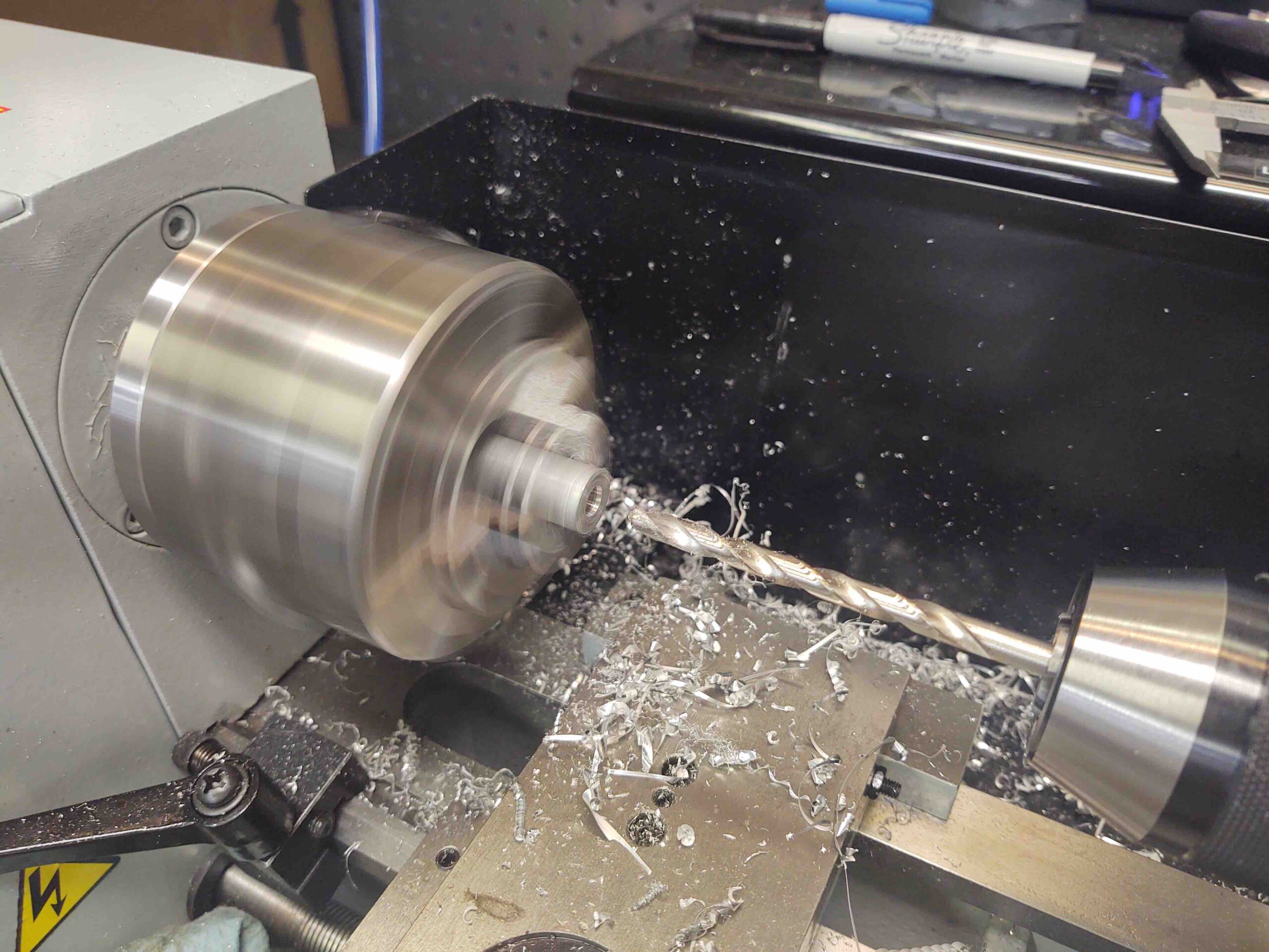
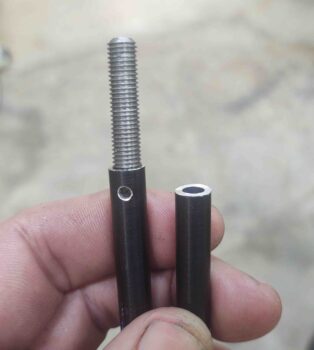
Since I was working with a foot-long rod of 6061 aluminum, and needed to keep it as straight as possible on the lathe, I needed to secure the far (non-chuck) side with what we call a dead center. Thus, the sharp point of the dead center needs an indentation to put its nose into to do its job… that’s where the diminutive center drill comes into play.
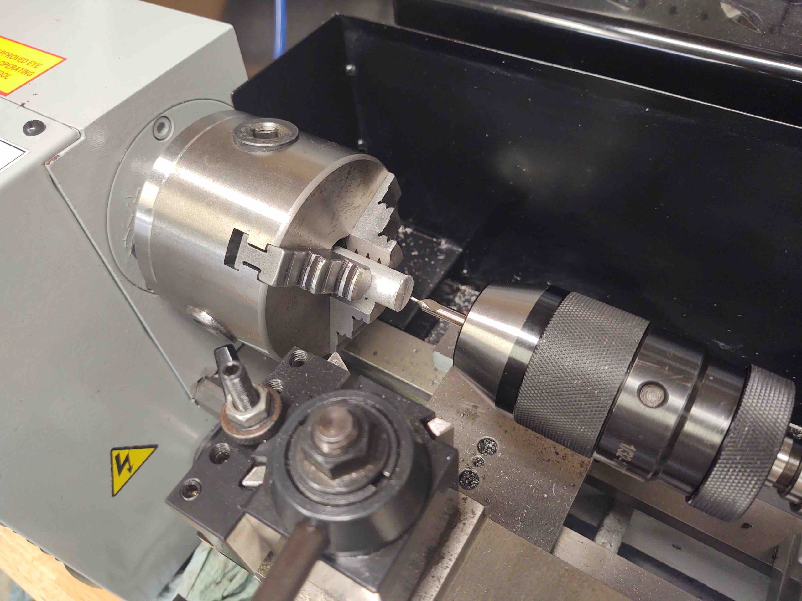
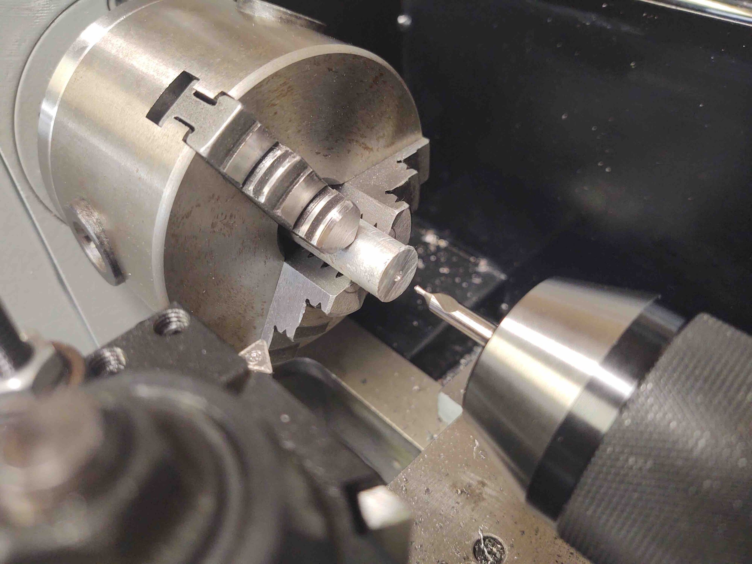
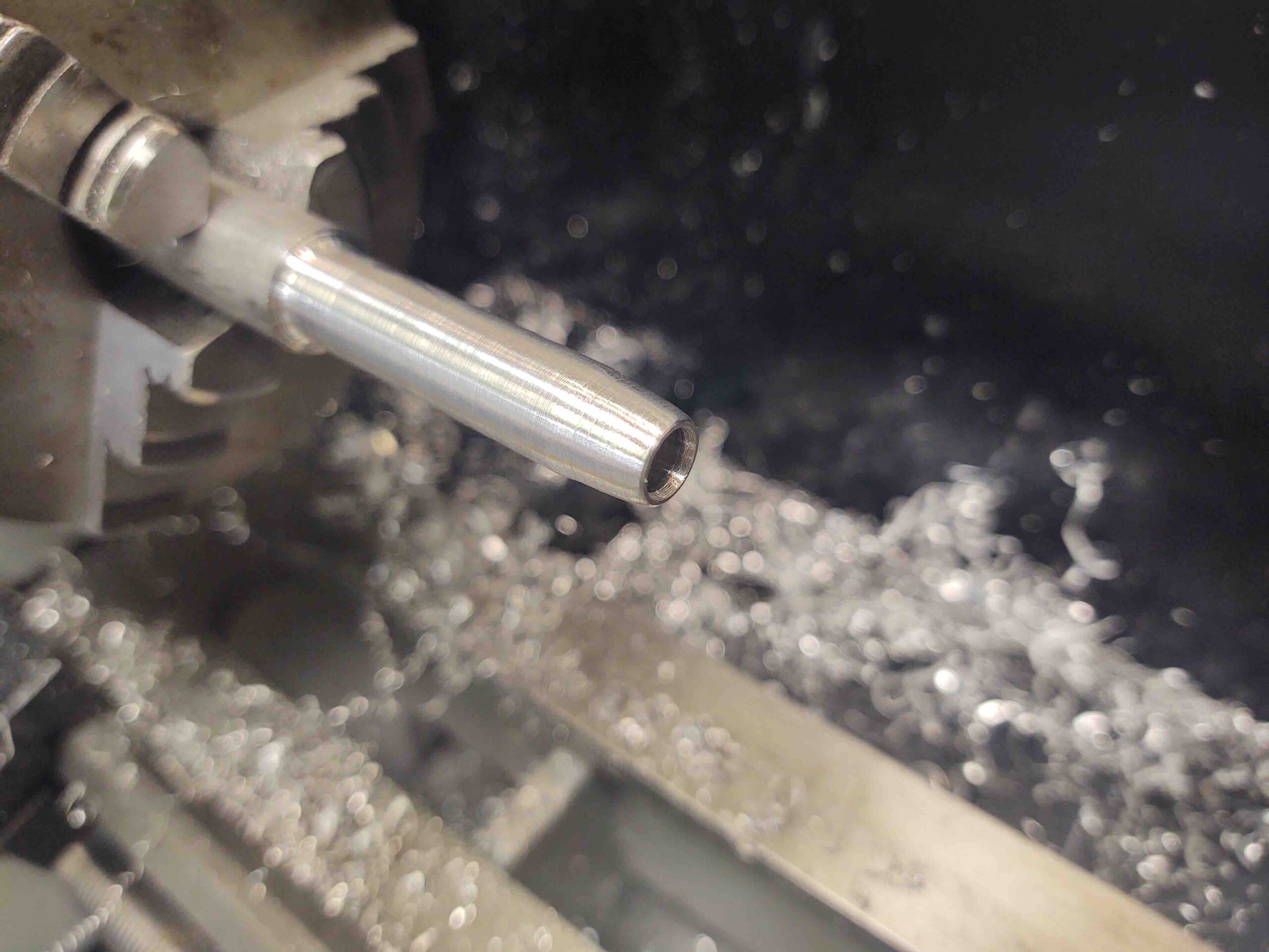
A bit later we have the finished (lathe-wise) canopy latch forward connecting rod.
Here’s a shot of the 3D printed canopy latch handle broken down somewhat in its component parts.
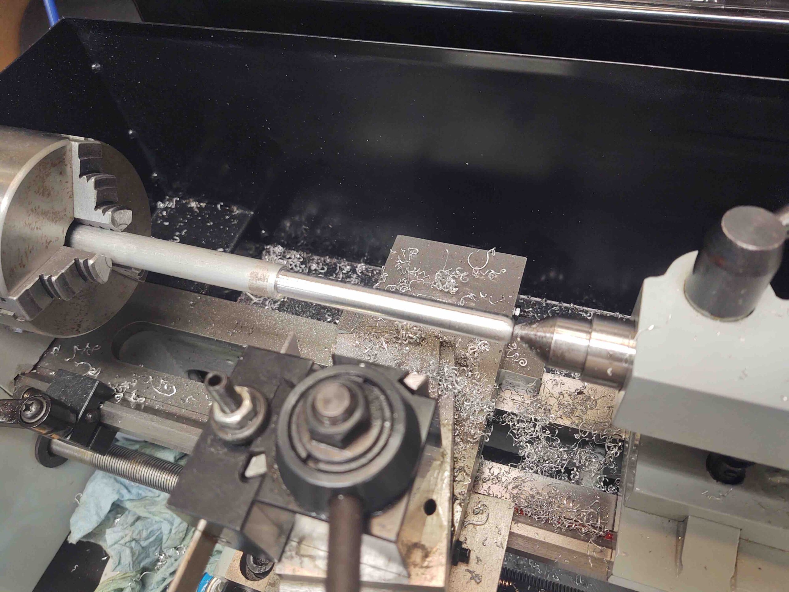
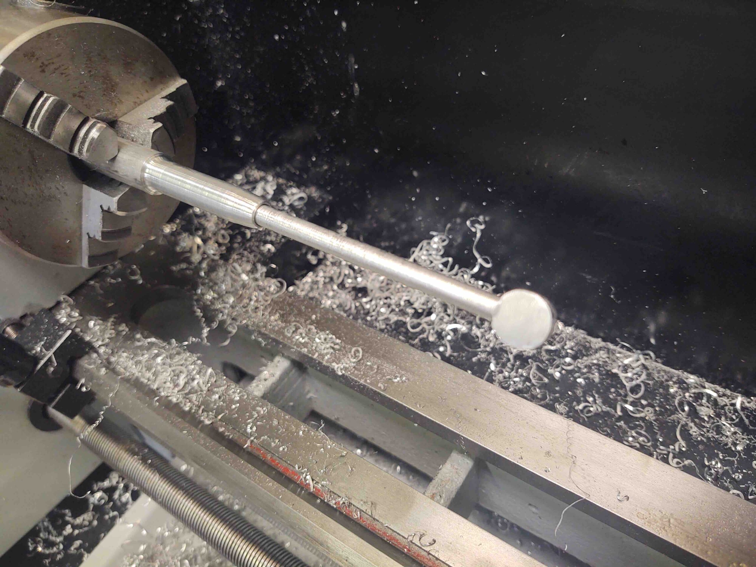
After round 2 on the lathe I created the aft interlinking connecting rod that will actually attach to the triangular piece, which then connects to the canopy latch hook rods. I’ll finish “machining” these parts tomorrow.
Note: In my haste I had carbide cutting tools loaded up in my quick change tool holders, so I used them since I couldn’t quickly locate the HSS tools (yes, my missing stuff insanity apparently continues!). The finish was acceptable, but if you look at the bigger/wider diameter section of the aft connecting rod you can see a much better finish… this was lathed using a HSS tool insert (found ’em, in the wrong drawer).
This shows the new forward connecting rod piece tolerance fit inside the handle piece works a treat.
•••
4 September 2020 — I started off today with machining more canopy handle parts on the lathe.
Here I’m drilling the hole in the back of the aft “nub” that attaches the triangular latch/rod interconnect to the handle mechanism.
Here’s the “nub” about ready to be separated from the aluminum bar stock. I free-handed the taper on the back and felt pretty good about the job I did on it.
Test fitting the canopy handle aft connecting rod. The round part on the right side (which was essentially a cylinder last night) will get a hole drilled through it to interconnect to the handle lever rod.
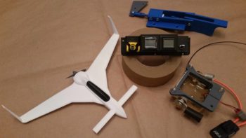
Here’s a shot of the original 3D printed proof of concept and operational test canopy latch handle and the build-in-progress real-world aluminum handle assembly.

As I designed on the original version, I drilled and tapped a 3/8″-20 threaded hole down the center of the handle block. I then reused the threaded 3D-printed sleeve as a guide for the connecting rod. When it wears out I’ll replace it with a phenolic one.
Here’s a few shots of the assembled canopy latch handle body.

Again, you can see the 3D printed threaded plastic sleeve peeking out the aft end of the handle body.
And then a few hours later after a seemingly unending myriad of drilling & tapping, the handle is finally together and ready for test mounting.
I’ll cut the triangular piece (gray plastic) tomorrow, but won’t get to CNC machining the main handle body (blue) until I get my mill online.
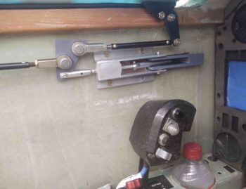
Here’s another few different shots of the handle assembly in various poses.
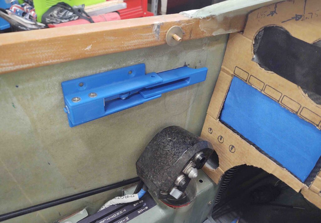
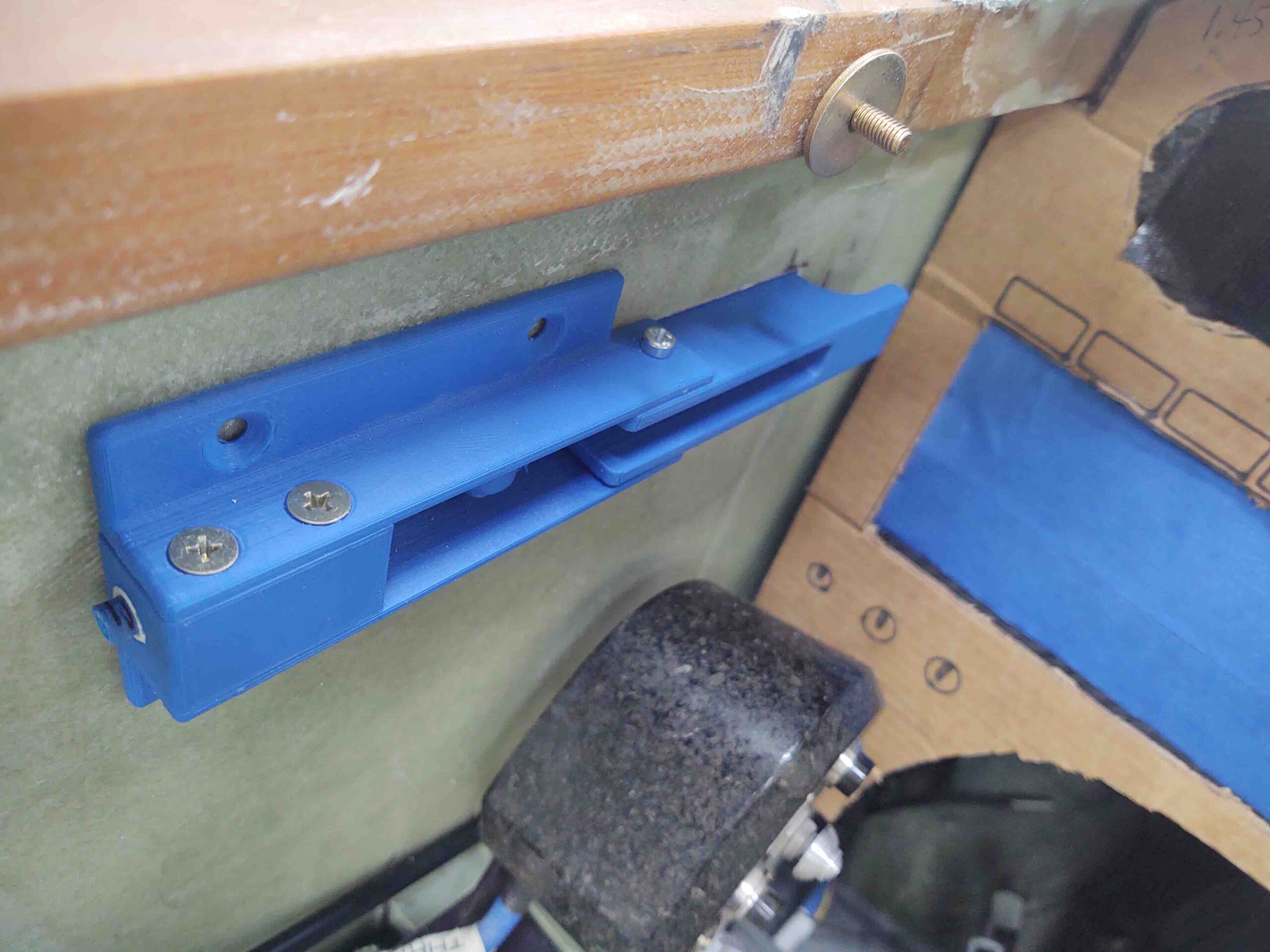
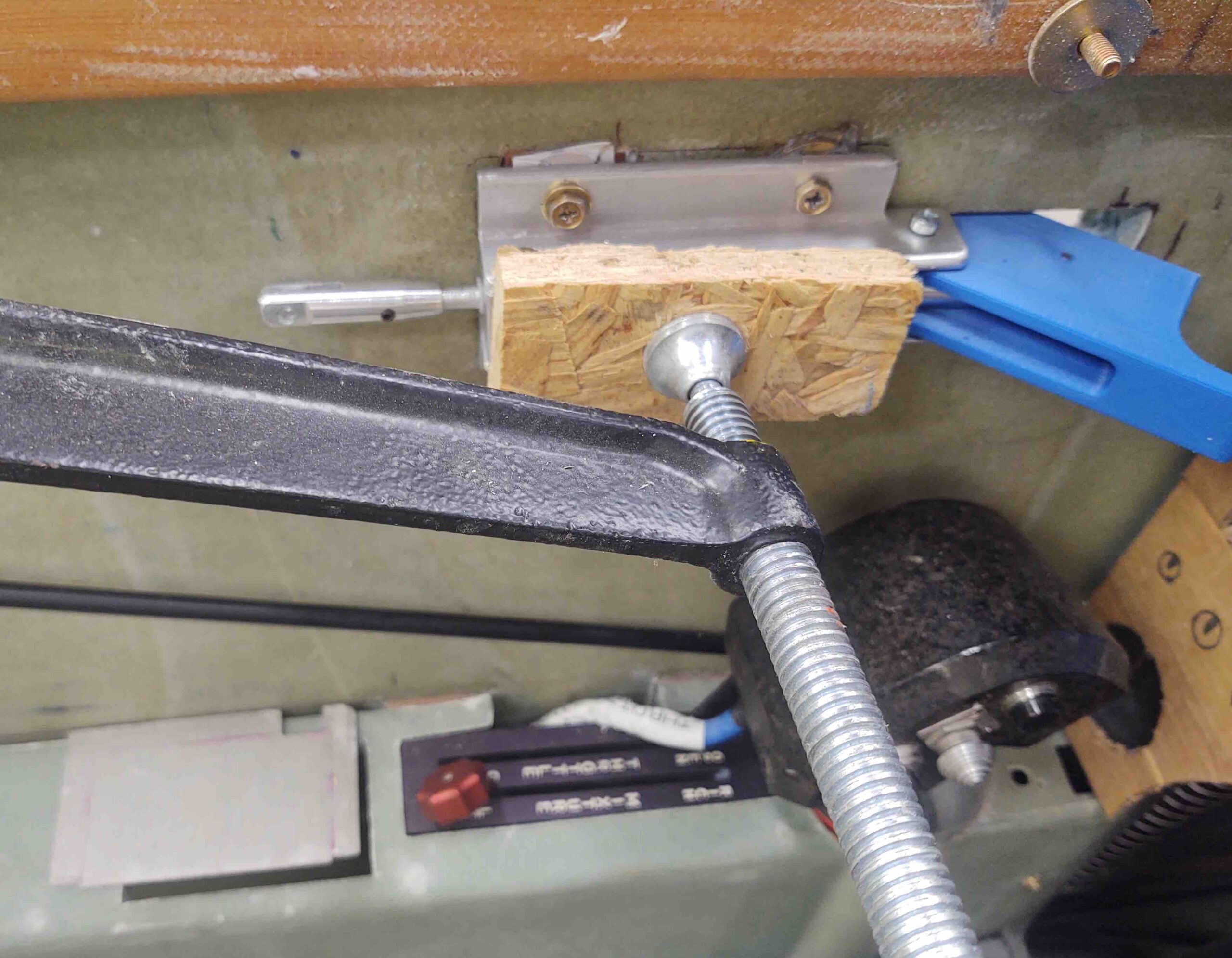
And finally, a shot of it in the bird. So happy to see this in place. Tomorrow I plan to gin up some nutplate assemblies and get this thing mounted in the fuselage for real.
And a bit closer view of it “installed.”
As a point of note, if you look closely in these last two shots you can see the outline of the Jack Wilhelmson handle just above the throttle handle. Although I’ve already covered it, you can really see how disruptive it would have been with my panel & throttle handle configuration.
•••
5 September 2020 — Today I got back to work on the canopy latch handle attachment to the left cockpit sidewall.
I started out with making up 3 nutplate assemblies: 2x #10 for AN3 bolts/screws (R side) and 1x for a #8 screw (L side). Two RivNuts will also be used to mount the handle assembly, both above and below the slot in the fuselage side.
The first task was to flox in the #8-screw nutplate assembly into the interior side of the canopy latch handle opening in the fuselage. I made the phenolic nutplate backer as wide as I could to fill back as much of the interior sidewall as possible simply to block as much incoming air as I can. This piece is just under about 30% of the entire width of the opening.
I guess I should tell you that the screw is a stop screw to adjust the depth of the handle at rest inside the fuselage slot. This keeps the exterior face of the handle even with surface of the exterior fuselage side. Clearly having a screw here makes it adjustable, but it should be a one time adjustment, “set it and forget it” type deal.
The small toothpick pieces are simply a backstop for pressing the phenolic piece into place. I removed them after the flox started greening.
A bit busier on the interior side, with a taped popsicle stick taped even more to the phenolic insert and the sidewall.
As the flox on the above insert piece cured, I cut the triangular canopy latch rod/hook interface piece out of 1/16″ (0.063″) 2024 aluminum. I didn’t drill the rod attach holes yet because I’ll actually test the geometry out using the gray 3D printed PETG plastic piece first.
I then got busy cleaning up the plasma cutting table, which desperately needed it. I had actually floxed in the above phenolic piece to get something curing because I was supposed to go swimming with my little buddy, but plans changed. Dinner was still on, so I figured I’d get some cleaning in….
Plus, I’ll actually need the plasma cutter to finish off the canopy (keep reading!).
Again, I used fast hardener for my MGS 285 epoxy. After a couple hours of flox-curing, I used the Fein saw to cut rectangles out of the inside sidewall skin for the canopy handle nutplate assemblies.
Test fitted here . . .
I then prepped the handle with the 2 nutplate assemblies and just one of the RivNuts –the top one– for floxing into the sidewall.
The reason I’m not mounting the lower RivNut is that I need to run a Nylaflow electrical conduit through the bottom of this latch opening out to the end of the left strake for the 2 GRT EFIS magnetometers. I don’t want to have to work around an intruding RivNut right in my path, so I’ll wait until l install the strakes to flox in the final, lower RivNut.
Also note that I had originally planned to criss-cross the RivNuts and nutplate assembly hard points, but upon realizing that I didn’t want to mess with cutting out a rectangular opening for a phenolic nutplate backer so close to the handle opening, I switched to nutplates on the aft end and RivNuts above and below the opening.
I then floxed the nutplates and RivNut into place in the sidewall. I clamped the handle in place and then left it to cure as I went to dinner at my friends’ house.
Almost 5 hours later I pulled the clamp off of the canopy handle assembly.
I then pulled the handle assembly off and cleaned up some of the oozing (cured) flox.
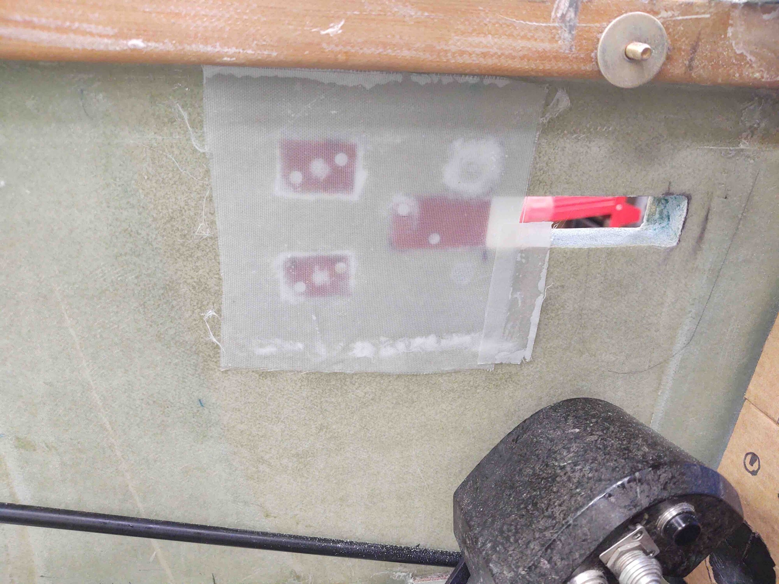
And then sanded the area down in prep for a 2-ply BID layup.
Which I did next… not forgetting the peel ply of course!
My last task in the shop for the evening was cleaning up the remaining plasma cutting table slats and putting them back in place.
Why am I messing around with the plasma table at this point? Well, as I mentioned above I will need it soon if I want to be diligent in finishing Chapter 18…. since I’ll use it to plasma cut the Canopy’s SC-1 Safety Catch.
Which was my last official build task of the evening: drawing this guy up in Fusion 360 CAD. After a few test runs, I plan on cutting the SC-1 out of some 0.018″ stainless steel (yep, the plans call for 0.02″… but hard to find in small quantities).
•••
6 September 2020 — Today I started out by pulling the peel ply and trimming the 2-ply BID layup securing the nutplates and one RivNut for the canopy latch handle mount. I then drilled out the glass covering the holes and dug out the protective plastic wrap (saran) that I had shoved in each one.
I then test mounted the handle assembly and it fit like a charm.
Although at first I thought I had my fore/aft mounting positioning off by about 0.050″, then I remembered the phenolic back plate needed a small U-shaped notch on the forward center edge of it to allow the handle linking rod to travel in unimpeded fashion.
A shot after the notch made in the phenolic back plate, and also the gray PETG triangular interconnecting plate back in play. Note the HEIM-4 rod-end connector, which I bought by mistake about 9 years ago and am just now putting to good use!
Here’s a shot of the front seat canopy latch system, sans the front hook and connecting rod (shown below).
And a couple of shots of the aft side in the GIB seat area.
I had to order a rod-end for the front latch hook rod so I won’t be able to truly test out the system for a few days yet. I’m kind of stepping out on a leap of faith here from just a few pics I have of an unknown Long-EZ’s –that BOTH Beagle and Terry Schubert couldn’t ID whose it was– setup with this central triangular connecting piece configuration. From what I can gather, it’s a type of mystical push-me/pull-me type setup where the rod force from the front hook and rear hooks play off of each other to push the rear hooks open while pulling the front hook open, then vice versa to close (rear pull, front push).
In addition to needing that rod-end connector (AKA “clevis”) to test out this setup, I also need to reprint the current blue PLA plastic handle with a more robust PETG or ABS (I should have that capability when I get the 3D printer back online) with the pivot bolt holes moved inboard about 1/8″. To dial in the canopy handle system I will keep both the aft triangular interconnect plate and front handle in plastic to modify as required. Once the configuration is good, I’ll drill/machine those parts in aluminum to finalize the canopy latch handle.
•••
8 September 2020 — Today was all about trying to figure out just what the heck is going on with my plasma cutting table. It had some initial teething issues back in May, mainly with some noise issues that I thought I had put to rest with some Ferrite Chokes on the USB cable connecting the control box to my laptop.
As I discussed in yesterday’s blog post, I thought I had found a more permanent fix to this issue. So I unceremoniously ripped the L1 inductor off the main board and soldered a bridge on the carnage that was left.
Well, today I tried it out. To be clear, this short video is not of today’s trials, but actually of yesterday’s initial plasma cuts that clued me in that trouble was a brewing . . . (I actually edited this video for the guys at Langmuir Systems to assist in troubleshooting my issues).
Today I was able to squeeze out another version of the SC-1 safety catch from my now Frankenstein scrap piece of 20 ga metal. I also drew up a 7mm wrench in Fusion 360 that I need to install a new hot end on the 3D printer, so I plasma cut it as well.
Although raggedy looking, this SC-1 worked fine as a fitting mockup to provide me notes on required (“desired”) modifications. Note my chicken scratchings on the piece itself.
Yet another shot.
I was then able to make the mods in Fusion 360 CAD for Mod 2.
Which I then tried to print out. As you can see (somewhat) on attempt #1 (right), the #10 holes are oblong and the center racetrack didn’t cut all the way through. #2 of Mod 2 was even worse as it had multiple non-firing/non-cut issues . . .
Here’s the underside of cut #1 of mod 2. Lot’s of dross on the top half edge, none on the bottom edge… very curious.
I posted the video, pics and my G Code to Langmuir Systems to resolve the issues.
•••
10 September 2020 — With an acceptable plasma-cut test SC-1 canopy safety catch part, MOD2, I was then able to test both fit inside/on the canopy, and clearance (tighter) of the center “racetrack” slot with and around the button head screw head . . . it looked good.
A couple more shots of the MOD2 SC-1. Note that while this may look like an acceptable candidate for a safety catch, it’s made of mild steel about 0.030″ thick. In other words, way too stiff to work for a flexible catch like the SC-1.
Knowing that my MOD2 upgrades passed the test, I was ready to cut the SC-1 out of stainless steel. The plans call for a 0.020″ thick piece of stainless steel, and this piece is pretty darn close to that.
In prep for plasma cutting the SC-1, I placed the sheet of stainless steel on the far back right corner of the plasma cutting table.
Why?
Well, plasma cutting stainless steel produces toxic fumes. In addition to my placement of the stainless steel sheet on the plasma cutting table, I also set up a large fan and opened up the big shop doors just behind the table. With such a small cut, this will do fine to mitigate and disperse any noxious fumes.
And here we have the SC-1 G-Code file loaded up in FireControl… ready for launch!
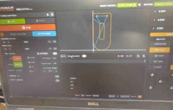
Yep, and here’s a short video of the SC-1 plasma cutout:
Here’s a still-frame shot of SC-1 cut out of the stainless still sheet. The incomplete perimeter cut is one of the issues I’m trying to figure out with Langmuir Systems. I was aware of that issue prior to this cut and simply chose to deal with the small tab using my trusty Dremel Tool.
Here we have the SC-1 canopy safety catch:
And the other side.
And the last SC-1 test mockup part (MOD2) with the actual new stainless steel SC-1.
Bending top SC-1 bolt mounting tab 90º.
Voila, here she is!
Again, just for comparison’s sake… I got the 45º bend seam just a bit higher on the actual SC-1, but with the spacer sleeve that goes over the button head screw on the longeron it actually was a great fit.
I then drilled the 2 mounting holes in the SC-1 canopy frame hardpoint.
A couple shots of the temp mounted SC-1 canopy safety catch.
Here we see a good shot of the SC-1 as I’m lowering the canopy…
Going down . . . SC-1 clearance with longeron.
Interior shot of SC-1 . . . note clearance with longeron: just over the thickness of an AN970-3 washer (I wanted a decent gap for clearance with the interior cockpit paint).
I marked and drilled the hole for the SC-1 longeron-mounted captive button screw, and then simply mocked this one up in place with the spacer sleeve on the screw.
SC-1 coming down over longeron captive screw, as per normal canopy-closing action.
SC-1 with canopy in nearly closed position (a slightly larger gap showing than usual).
SC-1 operating as designed: catching the captive screw either when the canopy is being opened on the ground, or as an emergency catch if the canopy attempts to fly open during flight.
On the ground the SC-1 is simply pushed inward (like a car hood latch) to clear the captive screw to then be raised.
•••
11 September 2020 — I started out today cutting a scrap piece of 1/16″ 2024 aluminum for the nutplate backer for the SC-1 captive bolt. Not following the plans exactly as I’m using a nutplate for the SC-1 captive bolt (vs just a standard nut) so that I can install the captive bolt later on/whenever I want and still close up the hole on outside of the longeron/fuselage. Then I can mount the SC-1 upper plate without worry of it catching the captive bolt at some point… that point being exactly as I’m working in the back seat with the canopy closed!
No thanks!
The back side of the SC-1 captive bolt nutplate.
And the assembly sitting atop the longeron in the same configuration as it will be once all mounted.
I then cut a notch out of the outboard fuselage top edge to mount the SC-1 captive bolt nutplate to the exterior side of the longeron.
I then cleaned up the inside of the notch.
I then whipped up some epoxy and made up just a tad bit of epoxy-alcohol mix to swipe the hole to seal it… which keeps the bolt from eventually soaking up moisture from the wood and rusting.
I then floxed all 4 longeron-mounted C2-L hook bolts into place, this pic showing the aft two.
A bit later I floxed the nutplate in place. Note that I also drilled 2 holes on opposite corners and floxed 3/32″ rivets into the longeron to ensure that the nutplate can be torqued.
I then left all the longeron-floxed stuff to cure as I got to work on the upper canopy frame SC-1 screw/bolts counter bores. Here I’ve marked them.
And then notched them out with the Dremel Tool.
•••
12 September 2020 — Today I replaced the upper outer fuselage chunk that I had removed to embed the SC-1 captive screw nutplate into the upper exterior fuselage sidewall, mounted to the longeron.
Here’s a pic after I micro’d the piece back into place, then covered with a piece of peel ply before some heavy duty duct taping to hold into place.
Quite a few hours later, this was the result. BTW, not wanting to waste MGS on this, I used West epoxy for the micro.
•••
14 September 2020 — Today I 3D printed out the new canopy latch handle in PETG. I used a high infill to make it strong so I can use it as an actual functioning handle to test & dial in the canopy latch configuration. I also moved the attach screw points inboard 1/8″ in Fusion 360 before re-printing the handle.
Here it is, cleaned up, in the front seat of the plane ready for installation (tomorrow).
•••
15 September 2020 — I got out to the shop early evening and immediately installed the new PETG 3D-printed canopy latch handle.
I needed to sand the front edge of the opening just a hair for it to fit, but after that it was good to go.
There’s still a very scant bit of the handle protruding past the fuselage surface, but I’m going to leave that for now since there will be some build up when the micro finish is applied to the fuselage.
•••
16 September 2020 — Today I got busy on the canopy.
First up was to replace C2-L #1’s latch screw (that the longeron-mounted hook catches) since I noted it was just barely clipping the inboard longeron edge and gumming it up. I had the screw all the way in so I either had to do some sanding on the longeron or make a new flatter, shorter hook screw (previous pic from initial install).
I’ve done a few of these now so it only took about 5 min to trim it up in the lathe. It fit a treat.
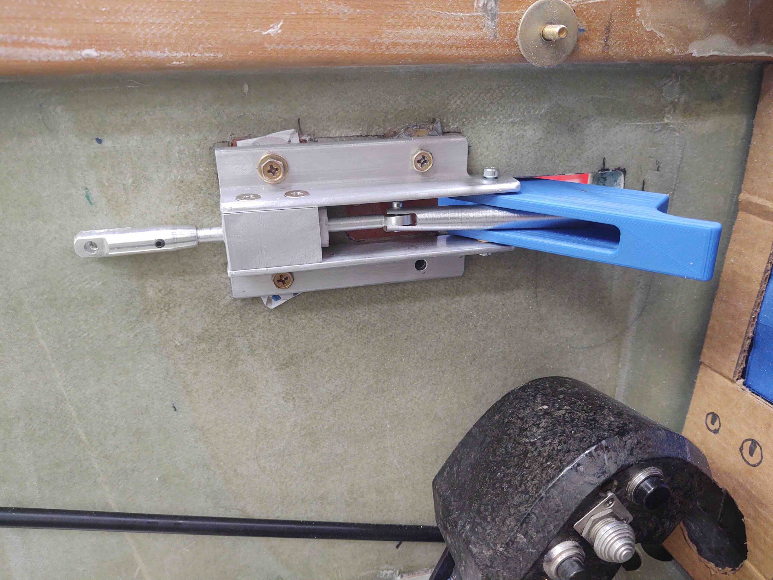
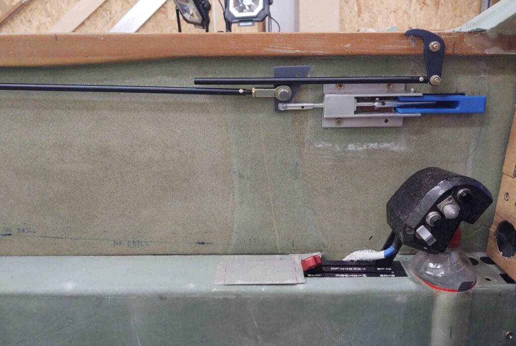
On the canopy latch, after playing with it for a while I realized the throw on the actuating rod was a bit too long. So I marked and trimmed 0.2″ off the end, as you can see it on the left side of the pic (just prior to cutting).

I needed to connect up the front canopy hook (C2-L) and its attachment rod to the aft 3 hooks (via the handle’s triangular interconnecting plate). This required deciding how long the connecting rod needed to be, cutting it, then tapping it for 1/4-28 threads, and finally drilling the freshly inserted threaded piece and connecting rod for a rivet.
Which you can see here. I then added a HM4 connector (I’d prefer to use lighter clevis-type connectors, but their connecting threads are 10-32, so some special adapters will have to be made before I use those).

I then mounted the #1 C2-L and its connecting rod to finally have the entire canopy latch system together for the first time.
Here it is in the canopy closed/locked position.
And in the canopy open/unlocked position.
I was sitting the plane, about ready to leave and call it a night, when I figured, “What the heck?” … let’s make a video to show you all what is going on with this thing.
So here it is:
•••
17 September 2020 — Today I tweaked the Fusion 360 drawing of the Canopy Latch connecting plate.
And then 3D printed it.
I spent a good 45 minutes in the cockpit working over details of the canopy latch and decided it needed yet another minor (or possible a BIG?!) mod.
I tweaked it yet again in Fusion 360 and printed that mod (I didn’t post a pic of the canopy handle because it looks pretty much as before).
This next round was more like an hour in the cockpit assessing the intricate workings of the canopy latch handle. I think I had a “Eureka” moment or two that I’ll share soon in a video: Essentially my statement in the last video about this attachment plate not being able to pivot is playing out to be true.
I need a better latch configuration that will allow me to both OPEN and CLOSE the latch in equally acceptable operations. I can see with the current configuration that I can tweak to an acceptable point on the unlocking & opening of the canopy, but not the locking and/or keeping the canopy closed.
•••
18 September 2020 — Today I jumped onto Fusion 360 CAD with some of my newfound canopy handle knowledge, and kicked off a 3D print of a new triangular connecting piece.
After installing this new canopy latch handle triangular connecting piece, I then spent another good hour assessing my canopy latch handle system. I honestly believe I’m pretty darn close to cracking the code. I came away with 2 more mods that I think will either get me to where I need to be on this handle, or really, really close!
•••
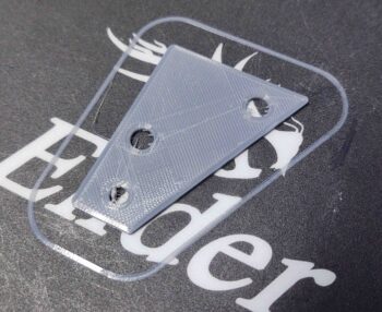
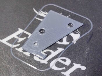
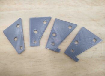
24 September 2020 — The canopy latch handle progression really comes down to this one critical part at its core: the triangular interconnecting piece. I snapped this shot to show just a few of the iterations it’s already gone through in just a couple of weeks.
And finally, here’s a video recounting the evolution of my canopy latch handle.
•••
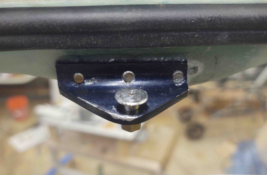
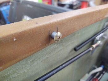
6 November 2020 — I started out today installing the AN3 bolts I finally ordered (and received) from Aircraft Spruce to attach the Canopy Safety Catch (SC-1).
Here are the temp screws that I used to hold the safety catch in place.
And the new AN3 bolts. The plans call for button head screws, but those are such a pain to deal with I just went with the bolts.
Here we have the inside with the nuts securing the SC-1 bracket in place.
To get the bolts level with the canopy frame surface I had to grind them down a bit with the Dremel Tool.
I then filled in the counterbore holes with dry micro, per plans.
•••
13 November 2020 — I actually plugged and glassed the oversized gaping hole that was in the pilot seat back for the canopy latch rod that traverses through it. Yes, this was more of a cosmetic task but since this is a fairly visible spot I wanted it cleaned up before the cockpit gets painted. In addition, I peel plied it to make the glass edge transition as smooth as possible.
Moving forward the plan is to simply re-drill a better sized hole for the canopy latch rod.
•••